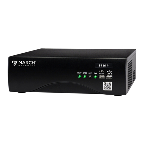
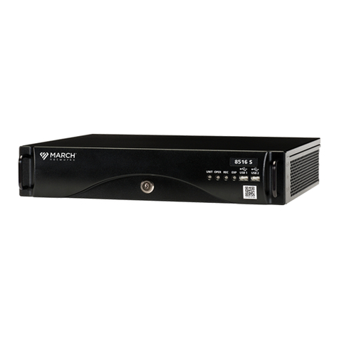
March Networks 8732 R, 8532 R User manual

March Networks
8000 Series Hybrid NVR
- 32/16 Channel
Models 8732 R, 8532 R or S, 8516 R or S
INSTALLATION GUIDE

© 2016. March Networks, An Infinova Company. All rights reserved.
Information in this document is subject to change without notice. MARCH NETWORKS, March
Networks Command, March Networks Searchlight, March Networks RideSafe, and the MARCH
NETWORKS logo are trademarks of March Networks Corporation. Infinova is a trademark of Infinova
Corporation. All other trademarks are the property of their respective owners.
The terms HDMI and HDMI High-Definition Multimedia Interface, and the HDMI Logo are
trademarks or registered trademarks of HDMI Licensing LLC in the United States and other countries.
North America.................................1 800 563 5564
Latin America..................................+52 55 5259 9511
Europe.............................................+39 0362 17935
Asia..................................................+65 6818 0963
Australia and New Zealand............+61 1300 089 419
Middle East and Africa...................+971 4 399 5525
marchnetworks.com
Notice of Rights
The software described in this document is furnished under a license agreement or nondisclosure
agreement. The software may be used or copied only in accordance with the terms of those
agreements. The contents of this manual and accompanying software are protected by copyright. No
part of this publication may be reproduced, stored in a retrieval system, or transmitted, in any form
or by any means, electronic, mechanical, recording, or otherwise without the prior written
permission of March Networks Corporation.
Part Number
28330 Rev 9.0, October 2016

8000 Series 32/16 Channel Hybrid NVR Installation Guide 3
Contents
Chapter 1: Mandatory Regulations ............................................... 5
Electromagnetic Interference (EMI) Information .................................................................... 5
Canada - Industry Canada ................................................................................................................. 5
United States - Federal Communications Commission .................................................................... 5
EU Directive Compliance............................................................................................................ 5
Battery Notices ........................................................................................................................... 6
NiCd Battery Pack Notice................................................................................................................... 6
Lithium Battery Notice ...................................................................................................................... 6
Safety Notice .............................................................................................................................. 6
Anti-Static Precautions .............................................................................................................. 7
Servicing Notice.......................................................................................................................... 7
Shipping Notice .......................................................................................................................... 7
Environmental EU Directive Compliance.................................................................................. 7
Model Definition Information................................................................................................... 7
Chapter 2: Feature Overview ......................................................... 8
Key Features ............................................................................................................................... 9
Packaging/Shipment Contents ................................................................................................ 10
Specifications ........................................................................................................................... 11
Dimensions of the R Series (with Docking Station) .......................................................................... 11
Dimensions of S Series (with Backplane) ........................................................................................... 11
Weight .................................................................................................................................................. 11
Operating and Storage Temperature ................................................................................................. 12
Power Ratings ...................................................................................................................................... 12
Video Inputs.............................................................................................................................. 13
Video Capture Rates................................................................................................................. 14
IP Camera Video Inputs ....................................................................................................................... 14
Front Panel LEDs....................................................................................................................... 15
Keyed Power Switch and Front USB Ports.............................................................................. 17
Keyed Power Switch ............................................................................................................................ 17
Two Front USB Ports ............................................................................................................................ 17

8000 Series 32/16 Channel Hybrid NVR Installation Guide 4
Contents
12-Volt Out, RS-485, and RS-232...............................................................................................18
12-Volt Out........................................................................................................................................... 18
RS-485 Interface ................................................................................................................................... 18
RS-232 Interface ................................................................................................................................... 18
Alarm and Switch Terminals ....................................................................................................19
Connecting an Alarm or Switch Device .............................................................................................. 19
Audio Terminals ........................................................................................................................20
Audio Input .......................................................................................................................................... 20
Audio Output....................................................................................................................................... 20
Ethernet Ports, USB Ports, Video and HD Monitor Output ....................................................21
Two Ethernet Ports and LEDs .............................................................................................................. 21
Two Rear USB Ports.............................................................................................................................. 21
Video Output ....................................................................................................................................... 21
HD Monitor Output ............................................................................................................................. 22
Power Connector and Fuse Compartment ..............................................................................23
Power Connector ................................................................................................................................ 23
Fuse Compartment .............................................................................................................................. 23
Replacing the Fuse............................................................................................................................... 23
Hard Drives ................................................................................................................................24
Hard Drive Details................................................................................................................................ 24
NiCd Battery Pack and Lithium Battery...................................................................................25
NiCd Battery Pack ................................................................................................................................ 25
Lithium Battery .................................................................................................................................... 25
Chapter 3: Unit Setup ................................................................... 26
Mounting the Recorder ............................................................................................................26
Rack-Mounting ..........................................................................................................................27
Wall-Mounting...........................................................................................................................27
Items Required to Wall-Mount.......................................................................................................27
Wall-Mounting with a Docking Station ............................................................................................. 28
Attaching the Drip Trays to the Docking Station .......................................................................... 29
Wall-Mounting without a Docking Station ....................................................................................... 31
Attaching the Drip Trays to the Recorder...................................................................................... 32
Desk-Mounting..........................................................................................................................33
Installing Hard Drives ...............................................................................................................34
Installing a Hard Drive......................................................................................................................... 34
Installation Requirements............................................................................................................... 34
Turning the Unit On and Off.....................................................................................................40

8000 Series 32/16 Channel Hybrid NVR Installation Guide 5
Chapter 1
Mandatory Regulations
You must be familiar with the following mandatory regulations governing the product’s operations.
You should also adhere to these instructions to ensure the installation meets regulatory compliance.
Electromagnetic Interference (EMI) Information
Canada - Industry Canada
This Class A digital apparatus meets all requirements of the Canadian Interference-Causing
Equipment Regulations. Cet équipement a été testé et certifié conformément aux limites imposées
par la réglementation en vigueur pour un équipement numérique de classe A.
United States - Federal Communications Commission
This equipment has been tested and found to comply with the limits for a Class A digital device,
pursuant to Part 15 of the FCC Rules. These limits are designed to provide reasonable protection
against harmful interference in a commercial environment. This equipment generates, uses, and can
radiate radio frequency energy, and if not installed and used in accordance with the installation
guide, is liable to cause harmful interference to radio communications. Operation of this equipment
in a residential area is likely to cause harmful interference, in which case users will be required to
correct the interference at their own expense.
Modifications not expressly approved by the manufacturer could void the user's authority to
operated the equipment under FCC rules.
EU Directive Compliance
This equipment complies with the following EU directives: 2004/108/EC and 2006/95/EC. A
Declaration of Conformity is available upon request.

8000 Series 32/16 Channel Hybrid NVR Installation Guide 6
Mandatory Regulations
Battery Notices
NiCd Battery Pack Notice
The unit contains an internal NiCd battery pack that is used during power shortages. The NiCd
battery pack may explode, leak, or get hot, causing personal injury if the following precautions are
not followed:
• Do not remove the NiCd battery pack and use it in a device other than the recorder.
• The unit has a built-in battery charger. Do not attempt to charge the NiCd battery pack using a
different battery charger.
• Replace only with an approved NiCd battery pack.
• Do not disassemble the NiCd battery pack.
• Do not open or try to open the individual NiCd battery pack cells.
• Do not dispose of the NiCd battery pack in fire.
• Do not short circuit the NiCd battery pack terminals.
Dispose of the NiCd battery pack in accordance with all applicable federal, state, provincial, and local
regulations. Inquire with your local recycling office for recycling guidelines.
Lithium Battery Notice
The unit contains an internal lithium battery that powers the clock and other system operations.
Ensure you consider the lithium battery when disposing of the unit. Dispose of the lithium battery in
accordance with all applicable federal, state, provincial, and local regulations. Inquire with your
recycling office for recycling guidelines.
Safety Notice
Before you access any components located inside the unit, turn the key counter-clockwise, to the
OFF position. After the status LEDs turn off, remove the power cord from the unit to prevent injury.
Only qualified service personnel should access the inside of the unit.
An AC power cord is provided with a grounded attachment plug. To avoid electrical shock, always
use the AC power cord and plug with a properly grounded outlet (connected to earth).
To maintain safety compliance, ensure the AC power cord has the appropriate safety approvals for
the country in which the equipment is to be installed. For North America, the AC power cord must be
a UL listed SJT NEMA 5-15 equivalent or better.
When connected to an outdoor camera, the screen of the camera’s coaxial cable must to be properly
grounded (connected to earth). Cable distribution systems are subject to the National Electrical Code
(NEC) in the United States and the Canadian Electrical Code (CEC) in Canada.
If you carry or move the NVR unit using the handles on the front panel, always use both handles. Do
not attempt to carry or move the unit using only one of the handles.

8000 Series 32/16 Channel Hybrid NVR Installation Guide 7
Mandatory Regulations
Anti-Static Precautions
Ensure proper use of an anti-static guard during installation to avoid damage to the unit from
electrostatic discharge.
Servicing Notice
The procedures contained in this publication outline how to install or service components located
inside the unit, requiring the removal of the cover. Installation and maintenance procedures
requiring internal unit access are to be performed by qualified service personnel only.
Shipping Notice
Shipment of the unit and components may expose the unit to temperature extremes. We
recommend you allow the unit to return to room temperature prior to operation.
Environmental EU Directive Compliance
March Networks is committed to doing our part to protect the environment. As a result, we have
embraced the RoHS and WEEE Directives in the design and manufacture of our products.
For more information, contact March Networks customer support.
Model Definition Information
The HNVR HS Series and the HNVR HR Series are regulatory models for the 8000 S Series and the
8000 R Series 32/16 Channel Hybrid NVRs. The model information is outlined in the following table.
Certification Regulatory Model Includes the following NVRs:
HNVR HS series • 8532 S
• 8516 S
HNVR HR series • 8732 R
• 8532 R
• 8516 R

8000 Series 32/16 Channel Hybrid NVR Installation Guide 8
Chapter 2
Feature Overview
The 32 channel or 16 channel 8000 Series Hybrid NVRs (Network Video Recorder) are scalable recording
platforms able to support both analog and high-resolution IP cameras. The models included are the
8732 R, the 8532 R or S, and the 8516 R or S.
The 8000 Series Hybrid NVR offers outstanding video compression and storage, and can be managed
using either the March Networks Command or the Visual Intelligence video management platforms.
Note: You can manage an
8000 Series Hybrid NVR using either of the management platforms offered
by March Networks. You should familiarize yourself with the differences between the platforms prior
to deploying the recorders. For more information, see the documentation available from the March
Networks Partner Portal.
The 8000 Series is available in two distinct types: the R series, which comes with a docking station for
mounting in a rack, and the S series, which is intended to be placed on a flat surface.
This section of the installation guide contains the following information:
• “Key Features” on page 9
• “Packaging/Shipment Contents” on page 10
• “Specifications” on page 11
• “Video Inputs” on page 13
• “Video Capture Rates” on page 14
• “Front Panel LEDs” on page 15
• “Keyed Power Switch and Front USB Ports” on page 17
• “12-Volt Out, RS-485, and RS-232” on page 18
• “Alarm and Switch Terminals” on page 19
• “Audio Terminals” on page 20
• “Ethernet Ports, USB Ports, Video and HD Monitor Output” on page 21
• “Power Connector and Fuse Compartment” on page 23
• “Hard Drives” on page 24
• “NiCd Battery Pack and Lithium Battery” on page 25

8000 Series 32/16 Channel Hybrid NVR Installation Guide 9
Feature Overview
Key Features
The 32/16 channel 8000 NVR comes in two distinct types: the R Series (8732 R, 8532 R, 8516 R models)
and the S Series (8532 S, 8516 S models). The R Series comes with a docking station and can be
mounted in a rack, the S Series has a backplane and is intended to be placed on a flat surface such as a
desktop.
The following table shows the key differences between the different models.
Some of the key features and benefits of the 32/16 channel 8000 Series NVR include:
• Video compression:
- Analog cameras — H.264 with multi-level encoding
- IP cameras — H.264, MPEG4, JPEG
• Eight alarm inputs, four switches, plus four mono audio inputs and two mono audio outputs, for
enhanced audio/video security coverage.
• High-capacity internal storage (up to fourx3TBSATA hard drives), with offset disk mirroring for
added reliability.
• Internal back-up battery for power brown-out protection.
• Advanced networking features for unlimited scalability and dependable remote access.
• Advanced health management features for centralized support and maximum up-time.
The R Series recorders slide out of the docking station for easy installation and maintenance.
Feature 8732 R 8532 R 8532 S 8516 S 8516 R
Camera Capacity
(total / analog / IP)
32 total / 16 analog / 32 IP 16 total / 16 analog/ 16 IP
Concurrent Frame
Rates
30 FPS per chan
at 4CIF / 2CIF / CIF
15 FPS
per channel
at 4CIF,
30 FPS at 2CIF / CIF
IP Camera
Bandwidth
32 chan at 3 mbps
= 96 mbps total
32 channels at 3 mbps
= 96 mbps total
16 channels at 3 mbps
= 48 mbps total
Docking Station
Yes No Yes
8000 R Series
Docking Station
Top of recorder
NVR

8000 Series 32/16 Channel Hybrid NVR Installation Guide 10
Feature Overview
Packaging/Shipment Contents
The following items are included in each system shipment, and should be located/verified before
installation begins:
• 8000 series network video recorder
• Docking station (R series)
• Keys for activating unit power (and locking the unit in the docking station for the R series)
• AC power cord
• Hard drive mounting screws - Four (4) screws per drive. If hard drives are installed, screws are in use.
• Data and power cables for the hard drives
• Software DVD — The software can also be downloaded from the March Networks Partner Portal.
• Technical publications — Included on the software DVD, or you can also download hardware and
software technical publications from the March Networks Partner Portal.
Note: A wall-mounting kit can be purchased separately if required.
WARNING:
The procedures contained in this guide outline how to install or service components located
inside the unit, requiring the removal of the cover. Installation and maintenance procedures
requiring internal unit access are to be performed by qualified service personnel only.
When working inside the unit, ensure you take anti-static precautions.
Any attempt to service components of the recorder that are not considered field replaceable
will invalidate your warranty. The list of field serviceable parts includes:
•
Hard drives, caddies, and cables
•
Back-up batteries
•
Fans
Do not power up or operate the unit with the cover removed. The cover ensures the safe
operation of the unit. Operating the unit without the cover can expose you to live electric
current and can cause the hard drives to overheat. Docking the unit without the cover can
also cause alignment problems and damage the docking station connectors.

8000 Series 32/16 Channel Hybrid NVR Installation Guide 11
Feature Overview
Specifications
This section contains the dimensions, weight, temperature ranges, and power ratings of the unit.
Dimensions of the R Series (with Docking Station)
Dimensions of S Series (with Backplane)
Weight
• R Series models with docking station (no hard drives): 18.5 pounds / 8.4 kilograms
• S Series models with backplane (no hard drives): 13.0 pounds/5.9 kilograms
• Each hard drive: Approximately 1.5 pounds / 0.7 kilograms
17.4 inches/44.2 centimeters
19.2 inches/48.8 centimeters
16.0 inches/40.6 centimeters
3.1 inches/8.0 centimeters
0.8 inches/2.0 centimeters
14.6 inches/37.1 centimeters
16.9 inches/43.0 centimeters
16.0 inches/40.6 centimeters
3.2 inches/8.1 centimeters

8000 Series 32/16 Channel Hybrid NVR Installation Guide 12
Feature Overview
Operating and Storage Temperature
• Operating temperature: 41 to 104°Fahrenheit/5to40°Celsius
• Storage temperature: -40 to 158°Fahrenheit / -40 to 70°Celsius
WARNING:
The recorder and docking station (if required) must be mounted in accordance with the
mounting guidelines in this publication to ensure the unit remains within the recommended
operating temperature range. For more information, see “Mounting the Recorder” on
page 26.
Power Ratings
• Power input: 100-240 volts AC input (auto-sensing)
• Current rating: 2.3 A
• Frequency range: 50-60 Hz
• Power consumption: 50 W (typical)

8000 Series 32/16 Channel Hybrid NVR Installation Guide 13
Feature Overview
Video Inputs
There are 16 analog video inputs on the back of the unit. The IP cameras can connect to the recorder
through a camera network on the camera Ethernet port (see “Ethernet Ports, USB Ports, Video and HD
Monitor Output” on page 21). IP cameras are connected using a CAT5e cable or a cable of higher
performance, such as CAT6 cable.
The number of IP cameras the unit supports depends on the number of analog cameras you are using
and the 8000 series model you have.
8732 and 8532 Models
The
8732 and the 8532 models support 16 IP-only camera channels and 16 hybrid channels for a total of 32
cameras. The 16 hybrid channels can be used to include any combination of 0-16 analog cameras and 0-16 IP
cameras, as long as the total number of cameras is 16 (excluding the 16 IP-only camera channels).
For example, if no analog cameras are in use, these
models
support up to 32 IP video cameras. If all 16
analog cameras are in use, they support up to 16 IP video cameras. The number of analog cameras in
use determines how many IP cameras you can add, for example, if you have only 10 analog cameras in
use, you have room for 22 IP cameras (32 cameras in total).
8516 Model
The 8516 model has 16 hybrid channels which
can be used to include any combination of 0-16 analog
cameras and 0-16 IP cameras, as long as the total number of cameras is 16.
The 8516 does not support any
IP-only camera channels.
For example, if no analog cameras are in use, the 8516 model supports up to 16 IP video cameras. If no
IP cameras are in use, it supports up to 16 analog cameras. You can combine IP and analog cameras (for
example, 8 IP cameras and 8 analog cameras) as long as they add up to a total of 16 cameras.
Video Inputs on BNC Coaxial Connector
The analog video inputs are BNC coaxial connectors that support NTSC (North American) and PAL
inputs.
Video Termination
Video termination for the 8000 series is controlled through the Visual Intelligence software. You can
use the March Networks Administrator Console application to view and modify the analog video
termination.
For more information, see the Administrator Console User Manual or online Help.
Video Inputs 1-16

8000 Series 32/16 Channel Hybrid NVR Installation Guide 14
Feature Overview
Video Capture Rates
This section details the video inputs and associated video capture rates.
The 32/16 channel 8000 series supports the following resolutions for analog cameras:
• 4CIF — 704 x 480 (NTSC) or 704 x 576 (PAL)
• 2CIF — 704 x 240 (NTSC) or 704 x 288 (PAL)
• CIF — 352 x 240 (NTSC) or 352 x 288 (PAL)
The FPS (frames per second) values are across all 16 video inputs.
8732 Model
The 8732 camera stream on the analog camera inputs supports all combinations of picture sizes and
frame rates. The frame rate limit is the same at any of the supported resolutions. Each NTSC camera
input supports up to 30 FPS and each PAL camera input up to 25 FPS.
•NTSC: 30 FPS per channel (all 16 channels) = 480 FPS at 4CIF/2CIF/CIF (full analog frame rate)
•PAL: 25 FPS per channel (all 16 channels) = 400 FPS at 4CIF/2CIF/CIF (full analog frame rate)
8532 and 8516 Models
•NTSC: 15 FPS per channel (all 16 channels) = 240 FPS at 4CIF
•PAL: 13 FPS per channel (all 16 channels) = 200 FPS at 4CIF
IP Camera Video Inputs
The IP camera input capture rate is dependent on the resolution and quality of the images captured.
The IP cameras have a recommended maximum of 30 FPS per channel at 4CIF for the 8732 model, and
15 FPS per channel at 4CIF for the 8532/8516 models.
8732 Model
The 8732 provides a capture rate of up to 3 mbps and 30 FPS per attached IP camera for 16 cameras (a
total of 48 mbps of inbound traffic from 16 IP cameras) and a capture rate of up to 3 mbps and 30 FPS
per attached IP camera for 32 cameras (a total of 96 mbps of inbound traffic from 32 IP cameras).
• 16 channels at 3 mbps = 48 mbps
• 32 channels at 3 mbps = 96 mbps
8532 Model
The 8532 provides a capture rate of up to 3 mbps and 15 FPS per attached IP camera for 16 cameras (a
total of 48 mbps of inbound traffic from 16 IP cameras) and a capture rate of up to 3 mbps and 15 FPS
per attached IP camera for 32 cameras (a total of 96 mbps of inbound traffic from 32 IP cameras).
• 16 channels at 3 mbps = 48 mbps
• 32 channels at 3 mbps = 96 mbps
8516 Model
The 8516 provides a capture rate of up to 3 mbps and 15 FPS per attached IP camera for 16 cameras (a
total of 48 mbps of inbound traffic from 16 IP cameras).
• 16 channels at 3 mbps = 48 mbps

8000 Series 32/16 Channel Hybrid NVR Installation Guide 15
Feature Overview
Front Panel LEDs
The colored LEDs (Light Emitting Diodes) on the front panel of the unit indicate status. Each tricolor
LED is marked to indicate which component the LED displays information about. The color of the LED
and whether the light is on solid, flashing, or off, gives you information about the recorder.
Unit LED
The status of
the unit.
Green Solid: The unit’s software and hardware are operating correctly.
Flashing: The keyed power switch has been turned off or power has been
removed — the system is waiting for software to complete the shutdown of
the unit.
Blue Solid: The operating system is loaded but the unit’s software application is still
loading.
Flashing: The unit is booting up after the keyed power switch has been
turned on or after a software reboot.
Red The hardware watchdog timer has expired and reset the system.
Operation LED
The status of
the unit’s
operation.
Green Solid: The software in the unit is operating correctly, and the unit is powered
and running.
Flashing: The operating system is available but the software is still loading.
Blue A system-level problem (non-critical) has been reported.
Red A critical error has occurred.
Use the Administrator Console or Command Client software application to
review the health alert and determine a possible resolution.
For more information, see the Administrator Console User Manual
or
Command Enterprise User Guide
, available from the March Networks
Partner Portal website.
Recording LED
The status of
the unit’s
recording.
Green Actively recording as configured (the recorder may be configured to record
continuously or only configured to record when triggered by an alarm or a
schedule).
Red A system-level problem has occurred which is affecting current recording or will
affect future recording.
Off The system is starting up or is not currently configured to record.
Front Panel LEDs

8000 Series 32/16 Channel Hybrid NVR Installation Guide 16
Feature Overview
Note: Information about operation and recording errors (indicated by the Operation or Recording
LED) can be retrieved using the Command Client or the Administrator Console (depending on which
software platform you are using, Command or Visual Intelligence).
For more information, see the Command Enterprise User Guide or the Administrator Console User
Manual, available from the March Networks Partner Portal.
Export LED
The status of
an export to an
external media
device.
Green Solid: Media transfer is complete.
Flashing: Media transfer is in progress.
Blue Solid: External media device detected.
Flashing:
• A request to export media clips to an external media device has been
initiated but the recorder is still logging the media. Exporting will not
start until the recorder finishes logging the media.
• Media clips are ready to be exported to the external media device but
no external device is detected.
• The external media device is full. Empty the device or insert a new one.
Red Failure of media transfer.
Off No external media device is connected or the external device is not usable.

8000 Series 32/16 Channel Hybrid NVR Installation Guide 17
Feature Overview
Keyed Power Switch and Front USB Ports
There is a keyed power switch and two USB ports on the front of the unit.
Keyed Power Switch
If the unit has a docking station (R Series), when the unit is powered on, the locking mechanism
prevents the unit from being undocked. Turning the key to the left in any 8000 model initiates shut
down. Once the LEDs are off, if the unit has a docking station, the unit can be safely removed from the
docking station.
Two Front USB Ports
There are two USB ports on the front of the unit for connection of external peripherals.
Each port provides up to 0.5 A to power peripherals with a USB cable.
The ports support USB version 2.0.
Note: Two more USB ports are available at the rear of the unit. For details, see “Ethernet Ports, USB
Ports, Video and HD Monitor Output” on page 21.
Keyed Power Switch 2 USB Ports

8000 Series 32/16 Channel Hybrid NVR Installation Guide 18
Feature Overview
12-Volt Out, RS-485, and RS-232
There is a 12-Volt Out connection, an RS-485 interface, and an RS-232 interface on the back of the unit.
Pinout
12-Volt Out
This connection is for powering external devices with a battery backed up source. It is intended for use
with the March Networks 2316 Encoder.
Maximum 12 Watts.
The Gindicates the ground connection pin and the +indicates the 12-volt positive connection pin.
RS-485 Interface
The RS-485 interface allows you to control a PTZ camera, with the following pins:
You can also use this to provide text capture with an RS-485 to RS-232 converter.
RS-232 Interface
The RS-232 interface allows you to provide text capture, with the following pins:
You can also use this to control a PTZ camera with an RS-232 to RS-485 converter.
Pin --- Rx+ Rx- --- Tx+ Tx- ---
Definition
Unused
pin
Input: Receive
positive
Input: Receive
negative
Unused
pin
Output: Transmit
positive
Output: Transmit
negative
Unused
pin
Pin
Rx G Tx
Definition
Input Ground Output
RS-485 RS-23212-Volt Out

8000 Series 32/16 Channel Hybrid NVR Installation Guide 19
Feature Overview
Alarm and Switch Terminals
There are alarm and switch terminals on the back of the unit. Alarm and switch devices can connect to
these.
Connecting an Alarm or Switch Device
Using the following procedure, you can connect alarm and switch devices to the terminals at the back
of the unit.
Note: The 8000 Series NVR does not support End-of-Line (EOL) resistors. Only Open and Closed
states are monitored.
To connect an alarm or switch device
1 Ensure the unit is powered down and the LEDs at the front of the unit are off.
2 Locate the appropriate alarm or switch terminals (refer to the graphic above).
3 Attach the device to the appropriate terminals:
For alarm devices:
• Use the G (ground) terminal closest to the alarm terminal when connecting the common wire.
Note: The alarm input is open/short, dry contact only.
For switch devices:
• Connect the switch device common wire to the appropriate common (C) terminal.
Note: The maximum voltage for a connected switch device is 60 volts DC input at 1 Amp or
60 Watts. Anything above 60 Watts must be handled by a second-stage relay control circuit,
approved and validated by certified electrician.
• Depending on the switch’s default state, connect the normally-open or normally-closed wire
to the corresponding normally-open (NO) or normally-closed (NC) terminal, respectively.
4 After you connect all of the alarm and/or switch devices, you can turn on the unit.
Switch Terminals
Alarm Terminals

8000 Series 32/16 Channel Hybrid NVR Installation Guide 20
Feature Overview
Audio Terminals
Audio in and out terminals are available on the back of the unit. These terminals provide line level
audio input and output.
Audio Input
Connect an audio cable to the Audio In terminal block.
Use the audio cable to connect an audio input device, such as a microphone, to the unit.
If you are connecting a microphone to the unit, you must use a pre-amplifier to amplify the signal to
line level. Place the pre-amplifier close to the microphone for best results.
Input specification: unbalanced, 10 kΩ, 1Vp-p (line level)
Audio Output
Connect an audio cable to the Audio Out terminal block. Use the audio cable to connect an amplified
audio output device, such as an intercom or speaker, to the unit. Ensure that the audio output device
(whether intercom or speaker) includes a built-in amplifier.
Output specification: unbalanced, 600 Ω, 1Vp-p (line level)
Pinout Description
Audio
In
1 Signal for audio input channel 1. Connect the return to the “G” between audio input 1 and 2.
2 Signal for audio input channel 2. Connect the return to the “G” between audio input 1 and 2.
3 Signal for audio input channel 3. Connect the return to the “G” between audio input 3 and 4.
4 Signal for audio input channel 4. Connect the return to the “G” between audio input 3 and 4.
G Return for the audio inputs. Each “G” is shared with 2 adjacent input channels. The 2 adjacent
input channels are the only channels that should use each return.
Audio
Out
1 Signal for audio output channel 1. Connect the return to the “G” between audio output 1 and 2.
2 Signal for audio output channel 2. Connect the return to the “G” between audio output 1 and 2.
G Return for the audio outputs. The 2 adjacent output channels are the only channels that should
use this return.
Audio In Audio Out
This manual suits for next models
4
Table of contents
Other March Networks DVR manuals

March Networks
March Networks 8724 V Tribrid NVR User manual

March Networks
March Networks CD-13887 Owner's manual

March Networks
March Networks 8516 Series User manual

March Networks
March Networks 8000 Series User manual

March Networks
March Networks 3108 User manual

March Networks
March Networks HNVR MS Series User manual