March Networks CD-13887 Owner's manual

TECHNICAL INSTRUCTIONS
CD-13887 Rev. 5.0 - February 1, 2006 Installing an Alarm Option Kit Page 1
Installing an Alarm Option Kit
These technical instructions provide details on installing an Alarm Option Kit on a March Networks 4000
Series recorder. The alarm and switch module, which is included in the Alarm Option Kit, is an external
device that provides additional inputs and outputs for connection to optional alarm and switch devices.
After you connect alarm and switch devices to the module, use the software applications to enable and
configure the devices, as required. For more information, see “Accessing the Recorder and Connected
Devices” on page 4.
Unpacking the Alarm Option Kit
Ensure the following items are located within the packaging:
Alarm and switch module (with installed mounting screws and lock washers)
20-pin terminal blocks (qty: 2)
200Ωend-of-line resistors (qty: 16)
WARNING!
Before you install an alarm and switch module, ensure you power down the recorder. For more
information see the installation guide accompanying the unit.
For 4000 Series DVRs, ensure the unit is running release 3.5 or later. For information about
determining the release, see the description of the showvers command in the Provisioning
Interface Technical Instructions. If the unit is running an earlier release, upgrade steps are
provided in the Upgrade Technical Instructions. Both publications are included on your March
Networks software CD.
The switch contact closure is designed to work only with low voltage devices. A rating of 30 volts
DC should never be exceeded. Also, the switch load should never exceed 1 amp. If you are unsure
about these specifications, consult an electrician before installing a switched device.

CD-13887 Rev. 5.0 - February 1, 2006 Installing an Alarm Option Kit Page 2
Installing an Alarm and Switch Module
To install the alarm and switch module, perform the following procedure:
To install an alarm and switch module
1
Turn off the recorder using the key and wait for the LEDs to turn off.
2
Align the 15-pin connector at the rear of the alarm and switch module with the 15-pin Expansion
Port at the rear of the docking station. The two pre-installed screws will align with the screw holes on
either side of the connector.
3
While holding the module in one hand, tighten the screws.
IMPORTANT:
• Alternate between the two screws to ensure that the module connects evenly to the docking station.
If you fully tighten one screw, then fully tighten the other, the module will not connect evenly.
• Do not overtighten the screws.
4
Slide the two terminal blocks into the slots on the alarm and switch module.
For easier access, we recommend you connect the device wires to the terminal blocks before you slide
the terminal blocks into the alarm and switch module. For more information, see “Connecting
Devices to the Alarm and Switch Module” on page 2.
NOTE
The alarm and switch module LED lights up when power is applied to the recorder.
Figure 1: Installing an Alarm and Switch Module
Connecting Devices to the Alarm and Switch Module
After you install the alarm and switch module, connect alarm or switch devices to the individual terminals
of the terminal blocks. Depending on the orientation of the terminal block, you may want to remove the
terminal block for easier access to the terminals.
Figure 2: Alarm and Switch Module Terminal Diagram
Terminal
Blocks
Screws
LED
A1
COM
COM
A2 A3
COM
COM
A14
A13
A15
A4 A5
A16
COM
NO1
NC1
A6 A7
C1
NO2
COM
A8
NC2
C2
A9
NO3
NC3
C3
COM
A10
A11
COM
NO4
NC4
C4
A12
COM
COM
COM
COM
ALARMS
SWITCHES

CD-13887 Rev. 5.0 - February 1, 2006 Installing an Alarm Option Kit Page 3
To connect an alarm device
1
Ensure the unit is powered down and the LEDs at the front of the unit are off.
2
Strip the end of the alarm device cable to expose the wires.
3
Strip ¼" of insulation from the ends of the wires.
4
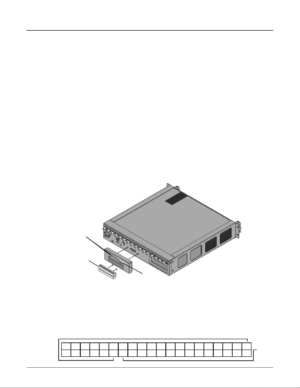
Locate the appropriate alarm terminals on the alarm and switch module terminal blocks.
Refer to Figure 2 on page 2, or the diagram on the alarm and switch module.
5
Loosen the appropriate terminals by turning the corresponding screws counter-clockwise.
6
Insert the wires into the appropriate terminals of the terminal block. We recommend you use the
COM terminal closest to the alarm terminal when connecting the common wire.
7
Tighten the terminals onto the wires by turning the corresponding screws clockwise.
8
Install a 200Ωresistor (included) in parallel with the alarm device, at the device. This allows the
recorder to detect tampering with the alarm device.
If the terminal blocks are not attached to the alarm and switch module, slide the two terminal blocks
into the appropriate slots.
9
After you connect all of the alarm devices, you can turn on the unit.
To connect a switch device
1
Ensure the unit is powered down and the LEDs at the front of the unit are off.
2
Strip the end of the switch device cable to expose the wires.
3
Strip ¼" of insulation from the ends of the wires.
4
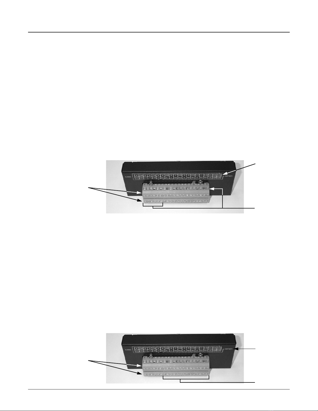
Locate the appropriate switch terminals of the lower alarm and switch module terminal block.
Refer to Figure 2 on page 2, or the diagram on the alarm and switch module.
5
Loosen the appropriate terminals by turning the corresponding screws counter-clockwise.
6
Insert the wires into the appropriate terminals of the terminal block:
• Connect the switch device common wire to the appropriate common (C) terminal.
• Depending on the switch’s default state, connect the normally-open or normally-closed wire to the
corresponding normally-open (NO) or normally-closed (NC) terminal, respectively.
7
Tighten the terminals onto the wires by turning the corresponding screws clockwise.
If the terminal block is not attached to the alarm and switch module, slide the terminal block into the
lower slot.
8
After you connect all of the switch devices, you can turn on the unit.
Alarm
Ter minal
Blocks
Diagram
Ter minals
Switch
Ter minal
Blocks
Diagram
Ter minals

CD-13887 Rev. 5.0 - February 1, 2006 Installing an Alarm Option Kit Page 4
Accessing the Recorder and Connected Devices
After you connect devices and apply power to the recorder, use the March Networks software applications
to enable and configure the devices.
Depending on the recorder model, the software applications you use to access the devices vary, as outlined
in the following table:
Recorder model Software applications Use this application to...
4000 Series DVR
DVR Configuration Tool •Enable and configure connected devices.
•Test device connections by turning devices on
and off.
DVR Viewer •Test device connections by accessing live and
recorded media.
4000 C Series NVR R5Installer Console •Test device connections by turning devices on
and off.
R5Administrator Console •Enable and configure connected devices.

CD-13887 Rev. 5.0 - February 1, 2006 Installing an Alarm Option Kit Page 5
About March Networks
March Networks™ (TSX:MN; AIM:MNW) is a leading provider of innovative IP-based video applications
used for security surveillance and monitoring. Our software and hardware solutions allow businesses to
increase operational efficiencies and address risk and asset management with an integrated set of video-
based intelligence tools that support enhanced decision-making. Today the ISO 9001:2000 certified
company serves the needs of leading banks, retail organizations and transportation authorities around the
world. For more information, please visit www.marchnetworks.com.
Accessing Customer Care
For technical support and assistance, contact us at:
If you purchased the DVR from a third-party organization, such as a March Networks certified reseller,
please contact the organization’s technical support staff.
Copyright Information
© 2006. March Networks Corporation. All rights reserved.
Information in this document is subject to change without notice. MARCH NETWORKS and the
MARCH NETWORKS logo are trademarks of March Networks Corporation. Windows® is a registered
trademark of Microsoft Corporation. All other trademarks are the property of their respective owners.
The software described in this document is furnished under a license agreement or nondisclosure
agreement. The software may be used or copied only in accordance with the terms of those agreements.
The contents of this manual and accompanying software are protected by copyright. No part of this
publication may be reproduced, stored in a retrieval system, or transmitted, in any form or by any means,
electronic, mechanical, recording, or otherwise without the prior written permission of March Networks
Corporation.
Tele pho ne: 1-613-591-1441
Toll free: 1-800-472-0116
Fax: 1-613-591-1858
E-mail: techsupport@marchnetworks.com

Table of contents
Other March Networks DVR manuals

March Networks
March Networks 8732 R, 8532 R User manual

March Networks
March Networks 8724 V Tribrid NVR User manual

March Networks
March Networks 8000 Series User manual

March Networks
March Networks 8516 Series User manual

March Networks
March Networks HNVR MS Series User manual

March Networks
March Networks 3108 User manual