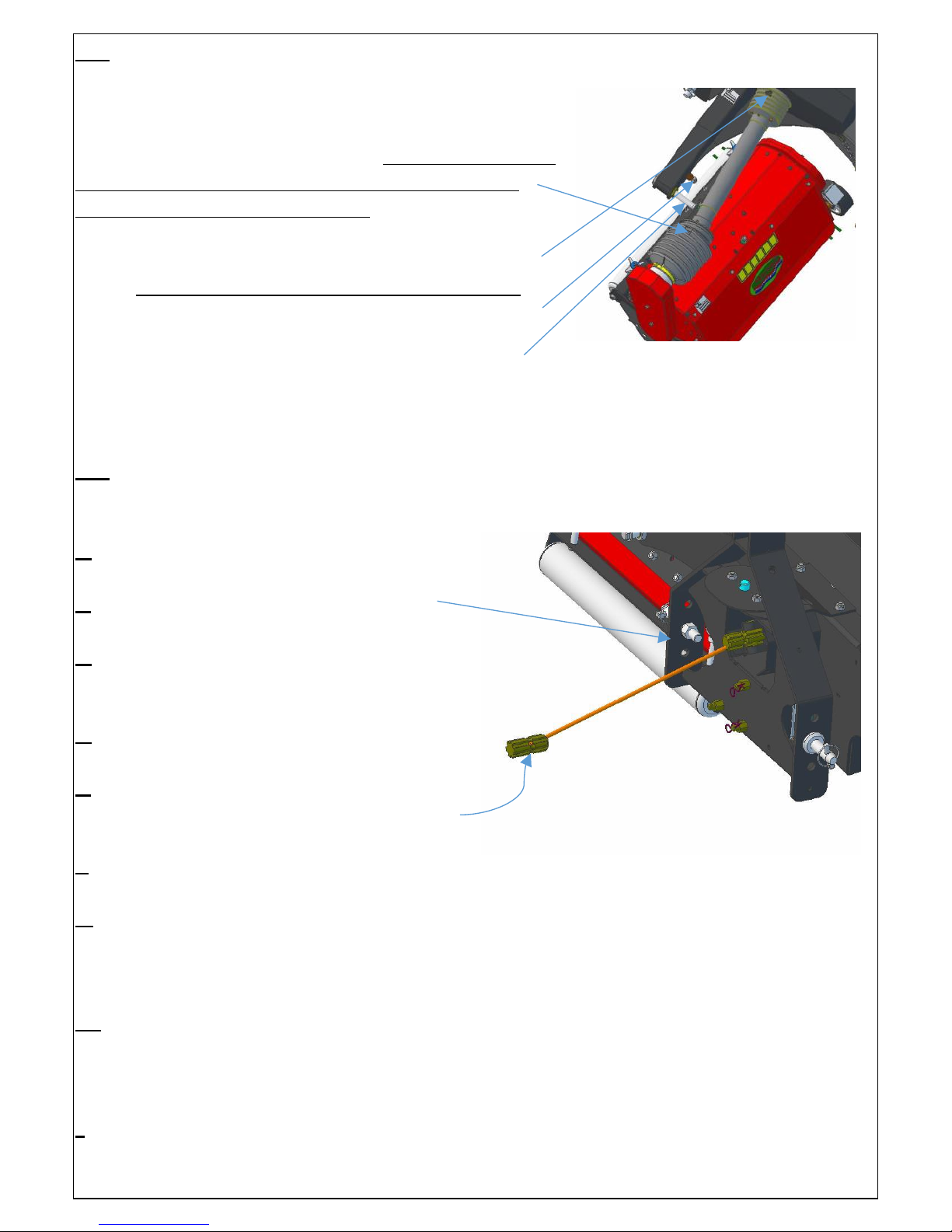
MAREDO MT210 User manual

1
Manual of MAREDO MT210
tractor mounted VibeSpike-Aerator
Serial #:
IMPORTANT NOTE:
This machine cannot run by its own. It needs a (compact) tractor to drive it. An
experienced driver is required, alongside a well-equipped, safe tractor.
MAREDO DOES NOT TAKE ANY LIABILITY FOR TRACTOR OR DRIVER
DAMAGES WHO ARE TO BE BLAMED BY MIS-USE OR MIS-CHOICE.
MAX. PTO REV. : 540 RPM
MAX GROUND SPEED : 10 KM/H 6 MPH.
Note:
For a safe operation it is essential, that the operator reads and under-
stands the manual of this Maredo MT210 and the tractor.
MAREDO BV, RIJKSSTRAATWEG 16, 3956 CR LEERSUM, NETHERLANDS.
WWW.MAREDO-BV.COM. EN 1829

2
1.0 SAFETY INSTRUCTIONS.
1. Never disconnect or shortcut any of the safety devices.
2. Every Maredo MT210 user must be fully informed and understand
the safe use of the MAREDO machine.
3. Inspect the ground, where the Maredo MT210 machine is to be
applied. Remove loose obstacles, avoid uneven areas.
4. Drive carefully during work and during transport.
5. Ensure that other people are standing at least 4 mtr./ 12 ft. away
from the Maredo MT210 machine during work and transportation.
6. The driver should use appropriate clothing. Wear strong shoes with
steel enforced toe caps, long trousers, gloves, tie up long hair and use
protection glasses for the eyes.
7. Choose the right tractor by checking the required specifications.
8. Never overload the Maredo MT210. This is visible when a head starts
vibrating or bouncing. The machine gets unsafe and may break down.
9. Check the Maredo MT210 minimal once a week, to ensure there are
no loose bolts and nuts. Check for damaged parts and repair them.
10. The Maredo MT210 may never be used without protection covers
and safety decals.
11. Use only original Maredo MT210 spare parts, in order to ensure the
safe operation of the machine.
12. Never use the Maredo MT210 in the dark, in heavy rain, on frozen
grounds, stony conditions and/ or on slopes steeper than 30 degrees.
13. Maintain a log book of the repairs.
14. Be aware that changes made at the Maredo MT210, may release the
manufacturer from any safety regulations. The machine should be
homologated by the party who made the changes.
Act on the safety instruction mentioned on the safety decal:
4 mtr/ 12 ft 4 mtr/ 12 ft

3
2.0 FOREWORD.
Congratulations with the purchase of your Maredo MT210 ® machine. To
ensure the safe and long lasting operation of this Maredo MT210 machine, you
and anyone else using this machine, should read and understand this user’s
manual.
Also ensure that you understand and practice the safety rules, as described in
this manual and shown on the decal.
This Maredo MT210 machine is delivered accomplished by a guarantee against
material, design and assembly errors. This guarantee applies for a period of 12
months, as from the date of purchase.
3.0 TECHNICAL SPECIFICATIONS.
Model : Maredo MT 210VibeSpike-Aerator.
Working width : 1900 mm/ 75”.
Working depth : 0-60 mm / 0 –2.4”
Spikes : Hardened steel. Thickness 4 mm/ 0.16”
Side to side spacing : 52 mm/ 2.2”
Gearbox oil : SAE 80/90 W for central gearbox
NLG 0 Grease for rear gearbox
Tractor size : Min 30 HP CAT I with 500 kg/ 1150 lbs lifting capacity
PTO speed : Max 540 rpm.
Weight : Complete machine: 390 kg/ 870 lbs
4.0 EU- DECLARATION.
We, MAREDO, Rijksstraatweg 16, 3956CR. Leersum, Netherlands, hereby
declare, fully on our authority, that the product:
MAREDO® MT210 VibeSpike-Aerator, with serial number as indicated on the
machine and in this manual, to which this declaration applies, has been
manufactured in line with NEN-EN –ISO 14121-1:2007, according to the
stipulations of The Machine Directive 2006/42/EG.
Marinus Reincke Maredo BV Holland.

4
4.0 UNPACKING AND FIRST SET-UP:
The Maredo MT210 machine is delivered on a specially
prepared steel pallet, at which the heads and the MFrame
are firmly packed. Assemble the machine as follows:
5.1. Remove all items from the pallet. Unscrew the rear
draw bar from the MFrame. In the end you should have the
following parts available: 3 x heads (RH, LH and rear one),
1x MFrame, rear draw bar, 2x PTO’s for RH and LH head ,
1x half PTO shaft for rear head, 1 x tractor PTO and 2 x
tube clamp d=80 mm (3”) to fix the PTO to the side heads.
5.2. Put the MFrame carefully with “it’s nose” on the floor.
5.3. Mount the rear draw bar with the 3 bolts, which go
through the rubber pivot block. Put the self-lock nuts at
the other side and tighten all 3 bolts well.
5.4. Connect the chain with D shackles at each side of the
rear draw bar. Tighten the D shackles well.
NOTE: Set the chain length at maximum. It can be
shortened later when the rear head is too close to the
ground, when the machine is raised.
5.5. Put the MFrame on its storage stands on the floor.
5.6. Mount the rear head first. The PTO is already pre-
mounted at the head side. Insert the other PTO half into
this one and next slide+ secure the PTO to the rear PTO
shaft of the MFrame gearbox. If the PTO is in place,
mount the rear head to the rear draw bar of the MFrame
with the 5 rubber blocks. Tighten all nuts (5) well.
5.7. Finally mount the two push-bars (2 x air spring) on
top of the head and draw bar and the rear head mounting
is completed.

5
5.8. Continue with the mounting of the side heads to the MFrame. This goes as
follows:
Mount the PTO with the long outer extension cover
to the heads first. IMPORTANT: when the extension
cover is secured with the tube clamp, be sure the
hole in the cover faces upwards.
Next insert the other PTO half and connect that side
to the MFrame gearbox. Secure the tube with the
chain. Again with the hole in the cover facing up.
Next mount the head to the MFrame. Remove the
pivot-bush + nut and also the nut of the notch.
Slide the head in place and tighten the pivot-bush nut and the notch-nut well.
Do exactly the same with the head at the other side. Be sure the holes in the PTO
covers face upwards too, like the PTO on the other side. That makes greasing easier.
5.9. It is important that the tractor PTO length is correctly determined. Not only when
the machine is new, but every time another tractor is used for this MAREDO machine.
The way to calculate the correct length for the PTO goes as follows:
A- Connect the Maredo MT200 machine
to the tractor’s 3 Point linkage.
B- Adjust the top-link so the Aframe is
vertical.
C- Move the tractor 3P-hitch up and down
and find the position at which the PTO
shaft is the shortest in length.
D- Set the 3 Point hitch at this position
and secure the machine + tractor.
E- Measure the length between the two
PTO shaft-ends from groove to groove
(=L1).
F- Next measure the length of the current
PTO drive shaft from secure pin to secure pin when the PTO shaft is fully in (= L2) .
G- If L2 is at least 50 mm or 2” less than L1 (which is needed for the free movement
of the PTO shaft), no action is required. If that is not the case take the PTO shaft apart
and shorten each PTO half (steel tube and plastic cover) : (L2 –L1) + 50 mm (or/2”).
H- Example: We measured L1= 500 mm (20”) and L2= 600 mm (24”). L2 is more
than L1, so we need to cut each PTO half (plastic + steel tube) with (L2 -L1) +50 mm
= (600-500) +50= 150 mm (or (24- 20”) +2”= 6”).
I- Deburr all the parts and mount the PTO shaft to the Maredo MT200 machine and
tractor. The PTO drive is ready to be used.

6
6.0 (FIRST) JOB PREPARATION + IMPORTANT NOTES.
6.1 TOPLINK & 3-POINT LINKAGE SETTINGS.
At the top of the Aframe we have 3 holes for the top link. If a higher hole is chosen,
the Maredo MT200 machine will be tilted
more forwards when raised. Which means more
clearance for the rear head. A clearance of at
least 200 mm/ 8” is needed for a safe travel job.
At the bottom we also have 3 holes. Check with
the stroke of the bottom 3p-bar of the tractor,
which one is the best. It is very important that
the 3P bottom bars have some travel left in the
bottom position to allow the machine to
following the undulations The connecting pins
can also be reversed facing to the centre (in case
we use a tractor with narrow 3P bottom bars).
A CAT II mounting kit is available and
recommended for tractors with a CAT II hitch connection.
Check the PTO length all the time, see point 5.9. When it is too long or too short,
damage to the driveline may occur.
Adjust the side-to-side swing of the 3P linkage stabilisations at the tractor side till it
swings approximately 150 mm./ 6” in total. This is needed to allow the machine &
tractor to make curves during work (Radius > 2.0 mtr./ 6’).
The top-link length is important, as it determines
the pressure on the rear head. The starting
position is always a vertical position of the A
frame.
The rear head is mounted to the MFrame via a
triangle drawbar. This drawbar is connected to
the MFrame via a rubber block pivot point (see
pt. 5.3). This pivot point allows the rear head to
move in all necessary directions and to follow the
undulations and curves. The A frame is also
mounted to the MFrame via a rubber pivot point.
This allows the tractor to make curves during
work. If the Aframe plus the MFrame is pushed backwards by enlarging the top link,
more pressure is put on the rear head via the rubber pivot points. This may help to
keep the rear head more stable on the ground. HOWEVER DON’T PUSH THE A-
FRAME TOO MUCH BACKWARDS (no more than 10° from the vertical position)
AS IT MAY HURT THE RUBBER PIVOT POINTS.
A Frame
M Frame
Top link
3P Bottom bar

7
6.2 DEPTH SETTING.
There are two depth adjusters per head. They can be adjusted by hand. Unscrew the
top secure nut (blue) first. Next the second spoke-nut can be turned. The front roller
will move up and down. At the decall you can read
the (theoretical) depth setting. Some NOTES:
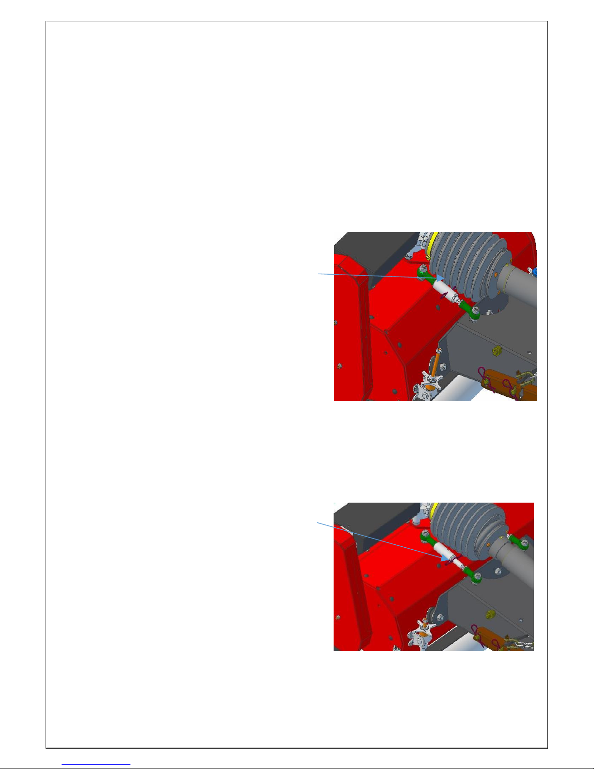
A- The theoretical depth setting is not the same as
the actual cutting depth. This depends on the
“softness” of the turf and how much the roller +
wheels are pushed into the turf. This deviation can
be corrected by moving the distance washes to the
top or bottom position.
B- Set both sides at the same depth.
C- Do NOT adjust one side more than 10 mm/ ½”
before compensating the other side.
D- If the (blue) lock nut is tight, “unscrew” it by
turning the big nut first.
E- After the depth setting is done, tighten the (blue) top nut to secure the setting.
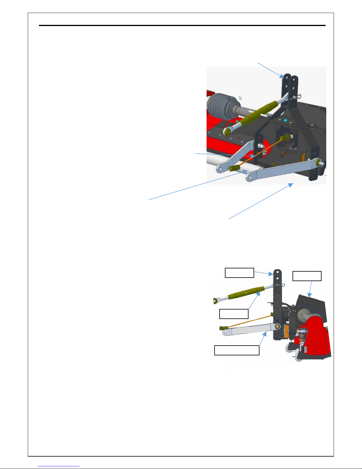
6.3. UNLOCKING THE AFRAME.
By removing the pin in the centre of the Aframe, the
A frame is unlocked from the main chassis and the
machine is ready to make curves during work.
For long transport travels, it is essential to put the
lock pin back in position, so the Maredo MT210
machine does not swing behind the tractor.
When unlocked put the pin in the storage hole, so
you can easily see if the machine is locked or not.
6.4. START EN STOP PROCEDURES.
6.4.1 Inspect the area that you want to treat.
Remove loose objects. DON’T USE the machine in the dark, in heavy rains, on
frozen grounds, stony conditions and on slopes steeper than 30 degrees.
6.4.2 Gently drop the Maredo MT210 machine all the way down till the spikes hit
the surface. Make sure the hitch control lever is in the lowest position.
6.4.3 Next start driving forward and engage the PTO and increase the engine revs till
the PTO runs appr. 540 revs.
6.4.4 The ground speed depends on the depth setting and the ground conditions. Start
with appr. 5 km/h (3 mph). Max speed is 10 km/h (6 mph) or till one of the heads get
unstable. Reduce the groundspeed at that moment immediately.
6.4.5 You can make curves, as long as they aren’t tighter than a radius=2.00 mtr./ 6’.
6.4.6 Important: Make sure the PTO is always switched off before lifting the MT210.
Running the PTO with a lifted MT210 may cause serious damage to the machine.

8
6.5 SECURE THE HEADS.
Standard the heads can individually follow the undulations via the front roller and the
rear roller. This is possible because the heads are flexibly mounted with rubber blocks
to the Mframe.
The heads can be secured for two reasons:
6.5.1 LOCK THE HEADS IN WORK POSITION.
The heads can be locked in the work position if
e.g. the heads are unstable in following the
undulations. If we lock the heads, they aren’t
following all undulations, but are more stable.
An R pin (or bolt M5) could be mounted
through the tube hole and the hole in the shaft.
The push bar is fixed as of that moment. The
depth can still be adjusted in the same way,
only the actual setting is not what is read at the
decal. Although the rear roller may not touch
the ground anymore, it will still prevent the
head from digging in (deep) undulations.
6.5.2. FIX IT IN THE STORAGE POSITION.
If the push bar is fully out (at the moment the
heads are raised and in the air), we can put an
R pin through the rod in front of the tube. This
can be used during storage/ transport purposes.
If the heads are locked this way, the spikes will
not touch the ground when the machine is put
on a (hard) surface.
This is one way to prepare the machine for
storage.
The other one is using the support storage
stands and is better because the weight of the MFrame does not rests on the heads, but
on the storage stands. You can use both options the same time.
Don’t forget to remove the R pin when the machine is put is work again.

9
6.6 DISCONNECT & STORE THE MACHINE.
Before you disconnect the machine from the
tractor, the machine will have to be set in the
storage mode. If that isn’t done properly, damage
to the machine and spikes may occur, especially
on hard (concrete) surfaces.
The 3 support stands should be placed in the
storage mode, which is vertically down. NOTE:
BE CAREFULL AS YOU ARE ENTERING A
DANGEROUS AREA AROUND THE
MACHINE AND THE TRACTOR.
When the 3 support stands are in the correctly
secured (vertical) position, the machine can be driven to the storage place and be
gently lowered on the stands. Disconnect the tractor and the machine is stored.
NOTE: Disconnect the machine only on a levelled, hard surface.
7.0 MAINTENANCE.
This Maredo MT210 machine is a low maintenance machine. Most bearings are
sealed and do not need re-greasing. The following maintenance is needed:
7.1. CLEANING THE MACHINE.
We strongly advise to clean the machine after every (daily) job. Use compressed air or
low pressure water. Be very careful with high pressure/ high temperature water
cleaners, as they may damage the moving parts in the machine and the paint.
If you clean the machine regularly, the dirt will not stick to the machine and the
machine will work better next time.
7.2 GREASE POINT/ GREASE INTERVALS.
All 4 PTO shafts are the most important items that need
greasing. They need one shot of EP (Extreme Pressure)
grease every 25 hours, starting with a first shot after the
first 4 hours. The PTO shafts that we use are easy to
grease as all (4) grease nipples per shaft can be
accessed from one side. As long as the PTO’s are well
assembled, the grease nipples of all 4 PTO can be
grease at once without having to rotate any PTO shaft.
4 grease
nipples
per PTO
IMPORTANT
Align all grease
nipple of all the
PTO shafts

10
Next, we have two more grease nipples that need a half shot every 50 hours. They are
located under the MFrame and they grease the front
pivot points of the two front units.
Also grease the depth adjusters of each head by 1/4
shot every 50 hours.
Don’t over-grease the grease points.
7.3 OIL CHECK AND REPLACEMENT.
There are two gearboxes mounted on this Maredo
MT210 machine. Both use the same gearbox oil SAE 80/90W. The first time the oil
needs to be replaced is after 100 hours of use. After that the oil will have to be
replaced every 300 hours or once a year.
The main gearbox is mounted on the MFrame and
drives all the 3 different heads.
Check the oil level at this plug
(in the middle at the front)
Fill or add oil through this plug
At the bottom, there is a plug to drain the oil.
The second gearbox is located on top of the rear MT
head and drives only the rear head. The oil level-plug
is located at the rear side of the gearbox. This is the
same plug to both drain and fill the oil. All machines
after July 2017 have a grease filled rear gearbox and
are maintenance free.
7.4 BELT DRIVE & REPLACEMENT.
The heavy duty V-belts need tensioning every 20 hours.
DON’T OVER-TENSION. The life time of bearings and V-
belts will be reduced.
The correct tension is achieved, when the V-belt-straight-
end (in between the two pulleys) can be moved sideward
by approximately 3 mm (0.12”). It must be re-tensioned
when this movement gets 10 mm (0.39”). The best way to
check the tensioning is by removing the top cover. This
allows an overall check at the same time. A quick check
can be done by using two 10 mm. (3/8”) rods, which are
put through the holes in the cover and placed on top of one
of the two V-belts. Push the rods one after another and
measure the chain (rod) movement. If the V-belt movement is more as described, re-
tensioning the V-belts.

11
Tensioning is done by moving the top shaft housing up and
down. Release the two nuts and next move the housing up
or down with the threaded stud + nut under the housing.
For the rear head it is important to check the alignment with
the gearbox as well. If the shafts are too much out of line,
re-position the gearbox with shims.
8.0 REPAIR & REPLACEMENT.
8.1 REPLACEMENT OF THE SPIKES.
In case the spike sections are worn out, they can be replaced as follows:
- Clean the MT210 heads
- Put down the three MT210 machine stands
- Lower the machine on it’s stands and disconnect the tractor. Make sure to place the
MT210 on a clean and even surface
- Remove the rear cover of each MT210 head as shown in the picture below.
- Each spike section is bolted with three bolts to the main shaft. Remove these three
bolts per section to take off the spikes. It might be necessary to rotate the spike section
located left or right of the spike section to take the bolt completely out.
- Re-mount the new spike section in the opposite way. Check the bolts for damages
and replace if needed. Make sure to use new self-locking nuts when mounting the new
spikes. Make sure to tight all nuts well.
- Re-mount the rear cover of the MT210 heads again.

12
9.0 SPARE PARTS.
For a complete overview of all parts for this MAREDO® machine, please look at our
web site under support (www.maredo-bv.com/support/).
Key part:
#1835232 Spike section (24 pcs. per head / 72 pcs. for three heads)
10.0 OPTIONS.
10.1 CAT II mounting kit.
This Maredo MT210 is specially designed for small compact
tractors with a CAT I - 3 point linkage.
If a bigger tractor (with CAT II hitch connection) is used, the
standard Maredo MT210 may not fit well.
A CAT II mounting kit is developed to turn the standard
Maredo MT210 connection into a CAT II version.
Table of contents
Other MAREDO Lawn And Garden Equipment manuals
Popular Lawn And Garden Equipment manuals by other brands

Schiller
Schiller RYAN 544859A Operation manual

Ramsey Electronics
Ramsey Electronics Rat Blaster RB1 Assembly and instruction manual

Perel
Perel GIK15N user manual

GreenWorks
GreenWorks PSF303 Operator's manual

greenhouse sensation
greenhouse sensation Hydropod Propagator Assembly and maintenance instructions

Gearmore
Gearmore XB48 Assembly, operation, service & parts manual