Mareli Systems ONYX AIR 8 KW User manual

ONYX AIR 8/10 KW Pellet stove
Assembly and exploitation manual
e present stove is designed and manufactured according to
Standards: BNS (Bulgarian National Standard) EN 14785-2006
Mareli Systems

2
Mareli Systems
Observing the prescriptions of the present manual is in the user’s favour and is one of
the warranty conditions. Compliance with this instruction is in the interest of the con-
sumer and one of the warranty terms.
• is appliance is not intended for use by people (including children) with limited physical, senso-
ry or mental abilities or lack of experience and knowledge. e installation must be performed by
a qualied expert in the eld of heating installations or authorized by “Marelli Systems’ service. e
place and way of connecting the stove should be selected carefully in accord with the safety instruc-
tions. Install away from ammable objects!
• Before starting any operation, the user must read and fully understand the contents of this in-
struction manual. Incorrect setup may cause hazardous conditions and / or incorrect function of
the stove;
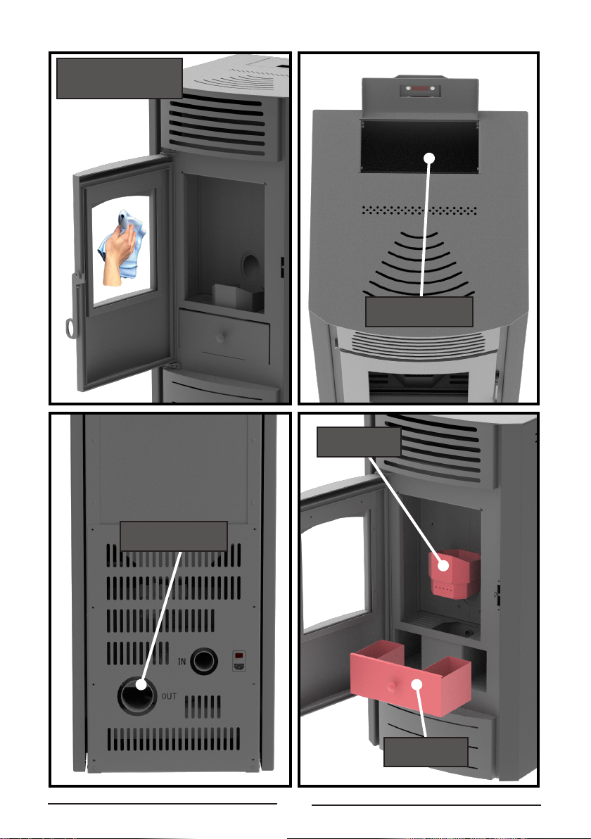
• Do not wash the stove with water. Water can get inside the replace and damage the electronics
and cause an electric shock;
• Do not put clothes to dry on the stove. Any clothes hangers and other objects must be located
within a reasonable distance from the replace. Fire hazard;
• e user is fully responsible for the proper use of the product which exempts the company from
liability of any users errors or misbehaviour or omissions;
• Any intervention or replacement that is made by unauthorized people or using non original spare
parts for the product can be risky for the user and release the company from all liability;
• Most surfaces of the stove are extremely hot (the door handle, glass, ue pipe, etc.). Avoid contact
with these parts before assuring yourself that you us temperature resistant gloves as well as suitable
temperature resistant instruments;
• Under no circumstances should the re be ignited with the door open or broken glass;
• e product must be electrically connected to a system equipped with an eective earth conduc-
tor. (Must be grounded);
• Turn o the stove in case of failure or malfunction;
• All unburned pellets in the burner aer each unsuccessful attempt ignition must be removed
before a new ignition;
• When installing the product all re safety requirements must be respected
If there is a re in the ue pipe, extinguish the stove, disconnect the power cord and never open the
door. Call competent authorized service technicians;
• Do not light the stove with ammable materials if the ignition system failed;
• Periodically check and clean the smoke outlet ducts of the stove (connection to the ue pipe);
• Pellet stove is not a cooker;
• Always keep the cover closed;
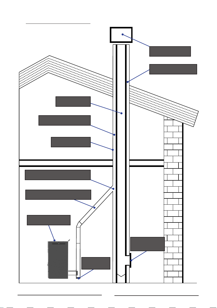
SAFE DISTANCES:
When installing the product a safe distance of at least 600 mm must be respected. is
distance applies to the product located near materials of B or C ammability level. e
safe distance is doubled if the product is close to materials of C3 combustion level.
INSTRUCTIONS FOR SECURITY:

3
Mareli Systems
1. PURPOSE
e stove is purposed to heat domestic and public premises by the means of pellets. e
stove is designed and manufactured to work with A-class pellets only ( DIN plus 51731
) with the following characteristics:
What are the pellets.
e pellets are produced by compressed wood-
en waste le from the production of various
furniture, sawmills and others. is type of
fuel is environmentally friendly because in
the production process no agglutinate agents
(glues, resins and others) are added. Actual-
ly, the integrity of the pellets is guaranteed by
the lignite – a natural ingredient contained in
the wood itself. While the wood has a calorie
capacity of 4.4 kW/kg (15% humidity at 18
months drying), the pellets have 5.2 kW/kg.
• Material 100% pure conifer or broad-leaf
wood;
• Diameter Ф6/8 mm;
• Length 20-30mm;
• Calorie capacity 5.2 kW/kg;
• Ash content < 8%;
e use of pellets with characteristics dierent from the recommended may result in
power decrease, unstable and inconsistent work of the stove.
Info: To ensure the proper work of the stove the pellets must be stored in a dry place!
Recharging of pellets can be done during work, with the following sequence:
1. Open the bunker (located at the top rear of the product);
2. Fill the hopper, using non-combustible container;
3. Close the lid of the bunker;
Attention!!! Use gloves! Beware of hot surfaces!

4
Mareli Systems
2. TECHNICAL DATA
Maximum output
KW
8
10
Heated area
m³
180
220
Height H
mm
1030
1030
Width W
mm
500
500
Depth D
mm
550
550
Pellet bunker volume
kg
15
15
Fresh air pipe
ф mm
48
48
Exhaust gas pipe
ф mm
80
80
Weight
kg
100
100
Fuel type
Pellets
Φ6-Φ8
Pellets
Φ6-Φ8
The chimney draft
Pa
12
12
Electrical consumption
V/Hz
60/310
60/310
Electrical supply
V/Hz
230/50
230/50
Fuel consumption
kg/h
0,3-1,6
0,3-2,0
Energy conversion efficiency
%
>91
>91
Co Emissions
Mg/m3
<300
<300
Temperature of the flue gas
C
160
165
Display
Pellet Bunker
Auger
Exhaust gas fan
Combustion
Chamber
Igniter
Heating fan

5
Mareli Systems
3. ASSEMBLY
3.1 General conditions.
All national, regional and European requirements for safe operation of the appliance
must be respected during installation and operation.
Prior to installation, load capacity of the place where the stove will be intended must be
ensured. e weight of the stove is specied in the technical data table.
To ensure the correct and safe operation of the stove, the following conditions must be
met:
e installation of the stove and its accessories must be carried out by authorized per-
sons.
e oor where the stove is installed should be at and horizontal, made of re-resist-
ant materials at least 1500 mm in front of the replace and not less than 400 mm on
both sides and at the back of the wall.
Minimum distances from the wall to the stove should be at least 400 mm. e mini-
mum space in front of the replace should be 1500 mm. e minimal distance of the
stove from combustion materials should be no less than 1500 mm.
e door of the replace should be closed tightly during the work process. Opening it
during work is absolutely forbidden.
When installing the stove, the connections between the individual pipes and the chim-
ney rooop must be dense.
When the re is rst ignited, a smell occurs as a result of the paint being heated.
e replace is painted with heat-resistant paint, which achieves its ultimate resist-
ance aer repeated use of the stove. THEREFORE KEEP OUTSIDE INTERACTIONS
WITH THE COATING TO A MINIMUM in order not to damage it.
A. A neighboring wall.
B. e rear wall.
C. Sidewall.
D. Floor protection.
E. Ignitable element.
1 = 400 (mm)
2 = 600 (mm)
3 = 400 (mm)
4 = 300 (mm)
5 = 1500 (mm)
6 = 120 (mm)
7 = 800 (mm)

6
Mareli Systems
CHECK ITEMS
BEFORE INSTALLATION
Chimney exit
Chimney
Connection to
chimney
Connection to
the stove
Security
distances
e oor
Inlet air
e chimney
revision door

7
Mareli Systems
3.3 Assembly of the duct components.
Duct components and pipes
For the assembly of the duct pipes the use of non-ammable materials, resistant to the ammable
products and condensation is obligatory. e assembly must be performed in such a manner so
it guarantees the airtight sealing and prevents condensation. If possible, avoid adding horizontal
sections. Direction shi is done by using knee joints with a max angle of 45˚.
For heating devices equipped with a smoke ventilator, i.e all of the “MARELI” stoves, the follow-
ing instructions must be observed:
Chimney
e chimney or the duct component must conform with the
following requirements: to be airtight, waterproof and prop-
erly insulated, to be constructed with materials resistant to
the normal mechanical wear and to the heat coming from the
combustion products and condensation.
• To be kept away from ammable materials.
e recommended chimney dra at work - from 12-20 Pa.
• Horizontal sections must have a minimum incline
of 3° upwards;
• e length of the horizontal sections must be as
short as possible, but without exceeding 3 m;
• More than four direction shis are forbidden,
including the cases where a T-shaped element is
used;
• e duct components must be airtight and to be
insulated if extending outside the premises in
which the replace is installed;
• e duct components must allow a soot cleaning;
• e duct components must have a constant sec-
tion. A section change is allowed only in the
chimney joint;
CHIMNEY EXITS (ANTI-WIND)
45
5 m (MAX)
(MAX)
Attention!!! In case of a re hazard turn o the product from the display. is will stop the oxygen
ow to the product.
Roof incline ≥ 10 °
Height above the roof = 40 cm
90°
Distance measured at 90 ° from
roof area = 1.3 m

8
Mareli Systems
3.4 Types of connection to the chimney
Chimney exit
Moisture channel
Chimney
ermal insulation
External wall
Connection to chimney
Flue gas connection
Heat generator
“T”
connection
e chimney
revision door

9
Mareli Systems
3.5 Air intake
Suction pipe or air intake is placed in the back and has a circular section with a diameter of 48 mm.
e combustion air can be aspirated:
• From the camera, as long as it is near an air intake communicating with the outside wall hav-
ing a minimum area of 100 cm2, properly positioned and protected by a grid.
• Or by connecting directly outside with a suitable tubing having an inner diameter of 48 mm
and a maximum length of 1.5 M.2
4. Cleaning
Cleaning the replace should be done only when cold. e cleaning of the combustion chamber
must be carried out daily. For this purpose, make sure the replace has ceased operation and is
completely cold. Pull up the combustion pot and remove it from the stove and then clean it from
soot. When removed fuel pot at the bottom of the combustion chamber opens a hole designed for
the accumulated ash. Collect ashes in the ashtray and return fuel pot in place and then close the
door. e replace is ready for operation.
Cleaning of ues and chimneys are conducted once every 1.5 tons of fuel used
Once clean audits and close the cleaning lid. Check that the bolts are tightened well. Every time
you open check for violations of the isolation seal. If this happens do not use the product until
the isolation seal is repaired.
Heating
exchangers
Combustion pot
Screw for maintenance

10
Mareli Systems
Cleaning the glass
Use an non-abrasive
cloth
Clean the ue gas
outlet
Cleaning the
pellet bunker
Combustion
chamber
Clean the
ashtray

11
Mareli Systems
5 Safety and unexpected risks
Terms of danger may arise in the following cases:
• Automated pellet stove is used incorrectly;
• e unit is installed by unqualied personnel;
• e safety instructions described in this management are not met;
Unforeseen risks:
Pellet replace “Mareli” has been designed and manufactured in accordance with the safety re-
quirements on the national, regional and European levels. Although considered possible risks
arising from improper use, you may experience the following risks:
• Risks of spreading combustion outside replace - opening the door of the chamber of the
replace may fall hot / burning particles (as hot ash and small particles burning coal), which
could lead to a re in the heated room. It is therefore necessary that the product always works
with a tightly closed door. It can only be opened when the product has completely cooled
down;
• Risks of burns caused by high temperatures as a result of the combustion process in the
combustion chamber and / or access to the door of this burn chamber when the product is
not completely cool;
In case of re hazard the product should be stopped by the controller and power supply until the
cause of the problem is determined.
Maintenance program
At each
ignition
Twice
per season
Weekly Annual
Combustion chamber
Clean the ashtray
Glass
e Door
Clean the ue gas outlet
Door seals
Chimney
V
V V
V
VV
V
V
V

12
Mareli Systems
ESC
G S W
L1
L5
L4
D2 D4D3
D1 P3
P1
P4
P2
L6 L7
L2 L3
KEY
CLICK
LONG PRESSURE
P2
Ignition / Extinguishing /
Block reset
Visualisations / Exit Menu
P1
ermostat modify (+) /
Increase data Pellet loading correction
P3
Combustion Power modify /
Save data
Manual pellet loading
P4 ermostat modify (-) /
Decrease data
Combustion Fan speed
correction
Values shown on the main frame
Display D1: time, system state, error, Menu,Submenu, parameter value; Display D2: power, parameter code;
Display D3: recipe; Display D4: main temperature, parameter code.
L1
L2
L3
L4
L5
G
L6
S
L7
W
Heating Fan On
Auger On
Ignition Resistance On
ermostat temperature reached
Daily program selected
Weekly program selected
Week End program selected
Control Panel: Use and Functions
Er01 - Security Error High Voltage 1. It may also intervene with the system o;
Er02 - Security Error High Voltage 2. It can only intervene if the Combustion fan is active;
Er03 - Extinguishing for low exhaust temperature or missing light in the brazier;
Er05 - Extinguishing due to high exhaust temperature;
Er06 - Pellet Thermostat open (ame return from the brazier);
Er07 - Encoder Error. The error may occur due to lack signal from Encoder;
Er08 - Encoder Error. The error can occur due to problems of adjustment of the number of revolutions;
Er11 - Clock Error. The error occurs due to problems with the internal clock;
Er12 - Extinguishing for ignition failure;
Er15 - Extinguishing due to power failure for more than 50 minutes;
Er17 - Adjusting the Air Flow Failed;
Er18 - No more Pellet in the bunker;
Er39 - Air Flow sensor damaged;
Er41 - Minimum air ow in Check Up is not reached;
Er42 - Maximum air ow exceeded (F40);
Er44 - Open door error;
Er47 - Error Encoder Auger: missing signal Encoder (if P81=1 or 2);
Er48 - Error Encoder Auger: Auger regulation speed not achieved (if P81=1 or 2);
Service - Service error. It noties that the planned hours of functioning (parameter T66) is reached.
It is necessary to call for service.
ALARMS

13
Mareli Systems
tA = Room Temperature [°C];
tF = Exhaust Temperature [°C];
tr = Remote Room temperature [°C];
UF = Speed Combustion Fan [RPM];
P1 CLICK
P1 CLICK (3 sec)
It is possible to activate the ignition process with long press on the P1 button;
It is possible to activate the extinction process with long press on the P1 button;
It is possible to clear the Block with long press on the P1 button.
Click on P2 button: the D2 display blinks. With other click of the
same button the power is changed. Ex.: 1–2–3–4–5–A (A=Automatic
combustion). Aer 5 seconds the new value is saved and the display shows
as normal.
Combustion Power Setting
P2 CLICK
USER MENU 1
ermostat Setting
P4 CLICK
P3 CLICK
P2 CLICK (3sec)
Manual Pellet Loading
Press the P3 or P4 key: the D3 display blinks. With sequential clicks on the
P3 / P4 button, it is possible to increase or decrease the set temperature of
the thermostat. Aer 5 seconds the new value is saved and the display shows
as normal.
e long pressure of button P2 activates the Pellet Manual Loading with
activation of Auger engine in continuous way. e bottom display shows the
word LoAd, the up display shows the elapsed loading time. To stop the loading
push any button. e loading stops automatically aer 300 seconds.
Description
Code
Sond
Hi
CLr
Port
OFF dEL
PCLr
-
Anomaly of the probes checking, during Check Up phase.
Room temperature greater than 50 °C.
is message noties that the planned hours of functioning (parameter T67) are reached.
Door Open.
e message appears if the system is turned o during Ignition (aer Preload) not manually:
the system will stop only when it goes in Run Mode.
Periodical Cleaning in progress.
No communication between motherboard and keyboard
MESSAGES

14
Mareli Systems
P3 CLICK (3 sec) Pellet Loading Correction
P4 CLICK (3 sec)
Combustion Fan Correction
e access to the menu is done by pressing P2 and P4 at the same time.
MODALITY
LED
Gior:
Daily Program , 3 programs for each day of the week;
WG S
SEtt:
Weekly Program , 3 programs for all days of the week;
WG S
FiSE:
Week-End Program , 3 programs for Mon-Fri and Sat-Sun;
WG S
OFF:
Programs Disabled;
WG S
e long pressure of P3 button activates this function (You have to do it two
times to access the modify modality). e bottom display shows PELL, the
upper display the value. With buttons P3/P4 the value is increased or
decreased; the default set is ‘0’. Aer 5 seconds the new value is saved and
the display shows as normal.
e long pressure of P4 button activates this function (You have to do it two
times to access the modify modality). e bottom display shows UEnt, the
upper display the value. With buttons P3/P4 the value is increased or
decreased; the default set is ‘0’. Aer 5 seconds the new value is saved and the
display shows as normal.
Heating Power (Air)This menu allows to change the heating power:
• Power manually set from 1 to 5.
• Heating Power set automatic by the system.
Chrono Enable Menu
This menu allows to select the chrono modality. On display appears the label ModE.
MENU FOR PROGRAMMING TIME RANGES
On display appears the label ProG.It has 3 submenus, one for each program modality:
Daily: it allows to set 3 programs for each day of the week
M o;
Weekly: it allows to set 3 programs for all days of the week
M S;
Week-End: it allows to set 3 programs for Mon-Fri and 3 programs for Sat-Sun
M F - S S;
Instructions - For each program, it is necessary to set the time on and the time o.
1) Scroll with the buttons P3/P4 until the wished Submenu and push the button P3 (G i o r n);
2) Push the buttons P3/P4 to select one of the 3 available programs;
3) Push the button P1 for 3 seconds;
4) Select the ignition time;
5) Push the button P2 to enter in modify mode: the selected value (hours or minutes) blinks. Push the button P3
to switch between hours and minutes, P3/P4 to modify the value;
6) Push the button P2 to save;
7) Select with the button P3 the O Timer and repeat the procedure from point 5;
For each time is possible to modify minutes with intervals of 15 minutes (e.g.: 20:00, 20:15, 20:30, 20:45).
Only for 11 p.m. is possible to increase minutes from 45 to 59, in order to get an ignition around midnight.
USER MENU 2

15
Mareli Systems
START
STOP
DAY
DAY
Using the P3/P4 buttons is possible to view all programs:
• e top of the display shows programs;
• No Programs is shown with (- - - -);
• e bottom of the display shows: day / time zone / start / stop;
Continuously pressing button P1 is possible to switch on / o the selected time.
Program Chrono across Midnight (00:00)
Set the ON time of the previous day to the desired value: Ex. 20h30;
Set the OFF time of the previous day: 23h59 Set the hour of the next day 00h00;
Set OFF time the next day: Ex. 6h30. e system turns ON at 20:30 from Tuesday to
Wednesday and turns OFF at 06:30.
Clock (oroL) - is Menu allows to set time and date. e above display shows hour and minutes, the
under display shows the day of the week. Push the button P2 to enter editing. e selected value (hours,
minutes, days) blinks. To change the value use the P3/P4 button. Push the button P2 to switch to modify the
other parameters. Push again P2 to save the set value.
State
Code
State
Code
State
Code
Off
-
Ignition-Variable ignition
On 4
Safety
SAF
Check Up
ChEc
Stabilization
On 5
Extinguishing
OFF
Ignition-Pre-heating
On 1
Run mode
-
Block
Alt
Ignition-Preload
On 2
Modulation
Mod
Ignition Recovery
rEc
Ignition-Fixed ignition
On 3
Standby
Stby
FUNCTIONING STATE VISUALIZATION
Remote room thermostat
(rEM )
This menu allows to modify the value of the Remote Room Thermostat, it is
visible only if one input is congured as remote room probe and is
P69 > 0.
Selector Menu (SEL)This menu allows to manage the position of the Selector and change the
heating air ow direction.
LoC - Air Flow in the room where is the stove.
rEM - Air Flow in the remote room.
Ducting Power (Can)It allows changing the Ducted Fan power:
• Power manually set from 1 to 5.
• Heating Power set automatic by the system.

16
Mareli Systems
1
2N
L
LINEA
3
4
5
6
FF
NN
FF
NN
V1V2
7
8
FF
NN
A1
9
10
FF
NN
C
13
12
11
H1H2
F
N
A2
14
15
21
20
+
_
IN1
23
22
GND
S2
IN2
25
24
GND
S3
IN3
27
26
GND
S4
IN4
29
28
30 +V
GND
S5
IN5
32
31
+V
+VC
34
33
GND
S6
IN6
36
35
GND
S4
IN7
CN1
RS232 RS485
POWER
CABLE
COMBUSTION
FAN
CANALIZATION
FAN
SAFETY
AUGER
PROTECTION AGAINST
RETURN FLAME
PRESSURESWITCH
EXHAUST
PROBE
ROOM
THERMOSTAT
ROOM PROBE
FAN
ENCODER
DISPLAY
LCD
PROGRAMMER
HEATING
FAN
IGNITER
DISPLAY
CP110

17
Mareli Systems

18
Mareli Systems


MARELI SYSTEMS disclaims any responsibility for possible inaccuracies contained in this manu-
al if they are due to printing or transcription errors. We reserve the right to make any change that
appears to be necessary or useful without harm the essential characteristics.
Mareli Systems
Mareli Systems
Industrial Zone
Simitli, 2730
Region Blagoevgrad
Bulgaria
info@mareli-systems.com
www.mareli-systems.com
This manual suits for next models
1
Table of contents
Other Mareli Systems Stove manuals
Popular Stove manuals by other brands

Morsø
Morsø 6840 Instructions for installation and use

Breckwell
Breckwell G29DV user guide

Enviro
Enviro Meridian FPI-2 owner's manual

Plamen
Plamen CALOREX 100 Tehnical instruction

HASE
HASE LHASA iQ Translation of the original operating instructions

EdilKamin
EdilKamin Celia Air Tight Plus Installation, use and maintenance

RIKA
RIKA RIKATRONIC3 IMPOSA operating manual

Broseley
Broseley eVolution 4 Installation & operating instructions

Country Flame
Country Flame NPS-1000 owner's manual

Nordica
Nordica VIOLETTA Instructions for installation, use and maintenance

FRANCO BELGE
FRANCO BELGE 174 06 94 Technical manual

Dimplex
Dimplex RIT20 Installation and operating instructions