MARELUX MX-R5 User manual


1
2
Important Notices
1. This product, Marelux housing body, must be used together with other Marelux parts and
accessories, for example, Marelux Extension Ring, Dome, Macro Port, etc. Using parts or
accessories from other Makers may cause malfunction or damage to this product.
2. This product is designed to be used at most 100m (330ft) under sea or fresh water level.
Please note that damage or leak can be caused to the product when the water depth is over
100m (330ft).
3. The lubricant inside the package is not edible and should be used only on the O-Rings in
Marelux products (Refer to the O-Ring notices section for more details).
4. Stop using this housing immediately when there is water leak.
5. Don't uninstall components from the housing body by yourself. Repair shall be done in
Marelux authorized service centers.
6. Always make sure the housing body is placed on a steady surface to avoid accidental falling.
Avoid striking or colliding that may cause damages to the product.
7. Avoid long time exposure in strong sunlight or extreme heat.
8. Don't open housing body in humid or sandy environment to avoid damage of electronic
circuit, or leakage caused by small objects.
9. Before opening the housing body, or uninstalling the extension ring and port when installing
lens, please clean the surface of the housing, remove water droplets, to prevent water or
foreign objects from entering into the housing.
10. Put the housing and its accessories out of young children's reach, to avoid small parts or
lubricant accidentally swallowed by children. In case this happens, please get necessary
medical treatment immediately.
11. Except for the lubricant that’s provided by Marelux, don't use any other chemical, cosmetic,
dissolvent material on the housing surface and its accessories.
12. If this product is not used for a long period, check the housing along with its accessories
carefully according to the manual before reusing it.
13. Marelux is not responsible for losing or damaging of user's photo, video or other form of user
data in the camera or memory card. Marelux is not responsible for damages of user's
camera, lens or other accessories when Marelux products are not properly used according to
this user manual. Marelux will take no responsibility for any mistakes or discrepancies in this
user manual.

1
3
O-Ring Notices
1. Always check carefully if there is scratch, crack, deformation on the O-Ring. Remove any
foreign objects such as sand, dust, or hair on the O-Ring.
2. For maintenance of the Marelux O-Ring, only use the original lubricant supplied by Marelux.
Any unauthorized usage of lubricant or chemical material from other brands on the O-Ring
may cause malfunction or damage of the O-Ring and even lead to leakage to the housing.
3. Change the O-Ring if there is any scratch, crack, deformation, avoid using tools with sharp
edge to change the O-Ring.
4. After ensuring the O-Ring is in good condition, use fingers to apply a thin layer of lubricant on
the O-Ring. Be aware that too much lubricant may make dust, sand, hair or other small
objects easy to stick on the O-ring.
5. Put the O-Ring straight into the O-Ring slot on the housing without twisting it.
6. Suggest taking out the O-Ring to check before each use of the housing.
7. If not used for a long time, please take out the O-Ring and put it in a cool place without direct
sunlight. Don’t put any pressure on it or twist it.
8. Don’t overstretch the O-Ring.
9. The recommended normal use time of O-Ring is 1 year and it varies due to frequency of
usage, maintenance and storage situation. Please replace it whenever any issue is found
during examination.

1
4
Part Names and Functions
(13)Handle
(14)Zoom Dial
(15)RF Lens release
(16)EF Lens release
Front+Back Side View
(16)
(15)
(11)
(14)
(13)
(10)
(12)
(9)
(8)
(7)
(6)
(5)
(4)
(3)
(2)
(7)Security Lock
(8)SET
(9)Delete
(10)INFO
(11)Enlarge
(12)Ball Mount
(1)
(1)RATE
(2)Alarm Light
(3)OK
(4)Auto-Exposure Lock
(5)Quick Menu
(6)Arrow Button
(34)
(34)Auto Focus Point Selection
1
5
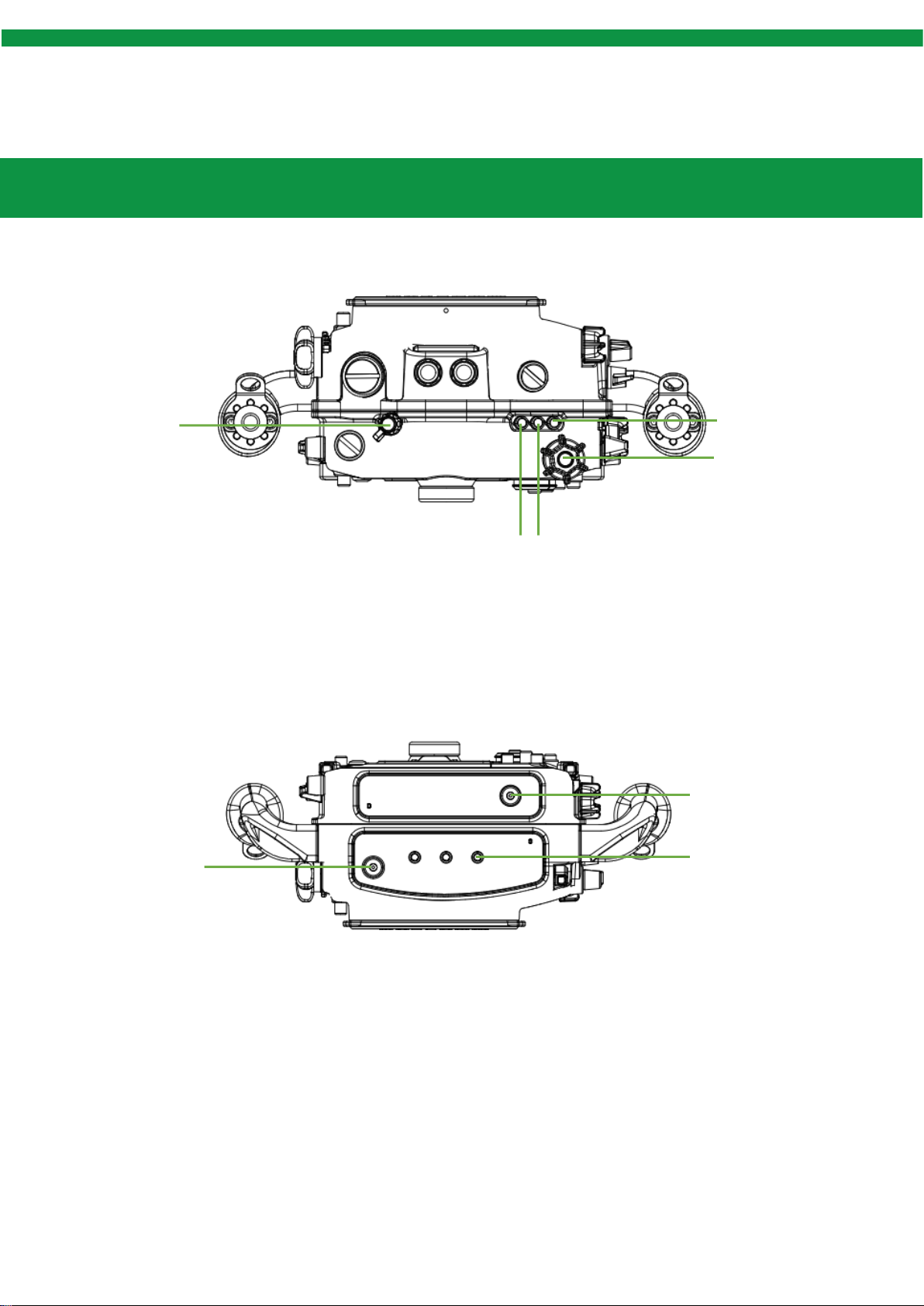
Part Names and Functions
Up+Down View
Up+Down Side View
(24)
(23)
(22)
(19)
(18)
(21)
(20)
(17)
(23)Sacrificial Anode
(24)1-20 UNC Screw Hole
(17)ON/OFF
(18)Speed Control
(19)MODE
(20)LOCK
(21)Rear Dial
(22)Sacrificial Anode
(23)LOCK
1
6
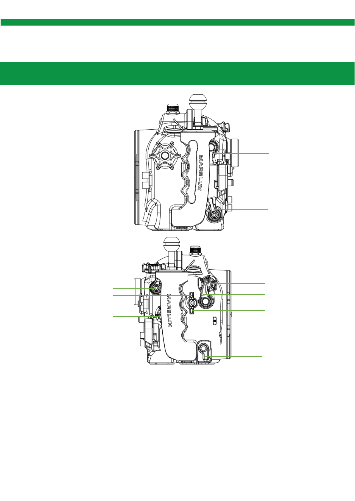
Part Names and Functions
Left+Right Side View
(32)
(33)
(31)
(30)
(29)
(28)
(27)
(26)
(25)
(31)Shutter
(32)REC
(33)LOCKOPEN
(25)MENU
(26)Replay
(27)AF-ON
(28)M-Fn
(29)Rear Dial
(30)Front Dial
1
7
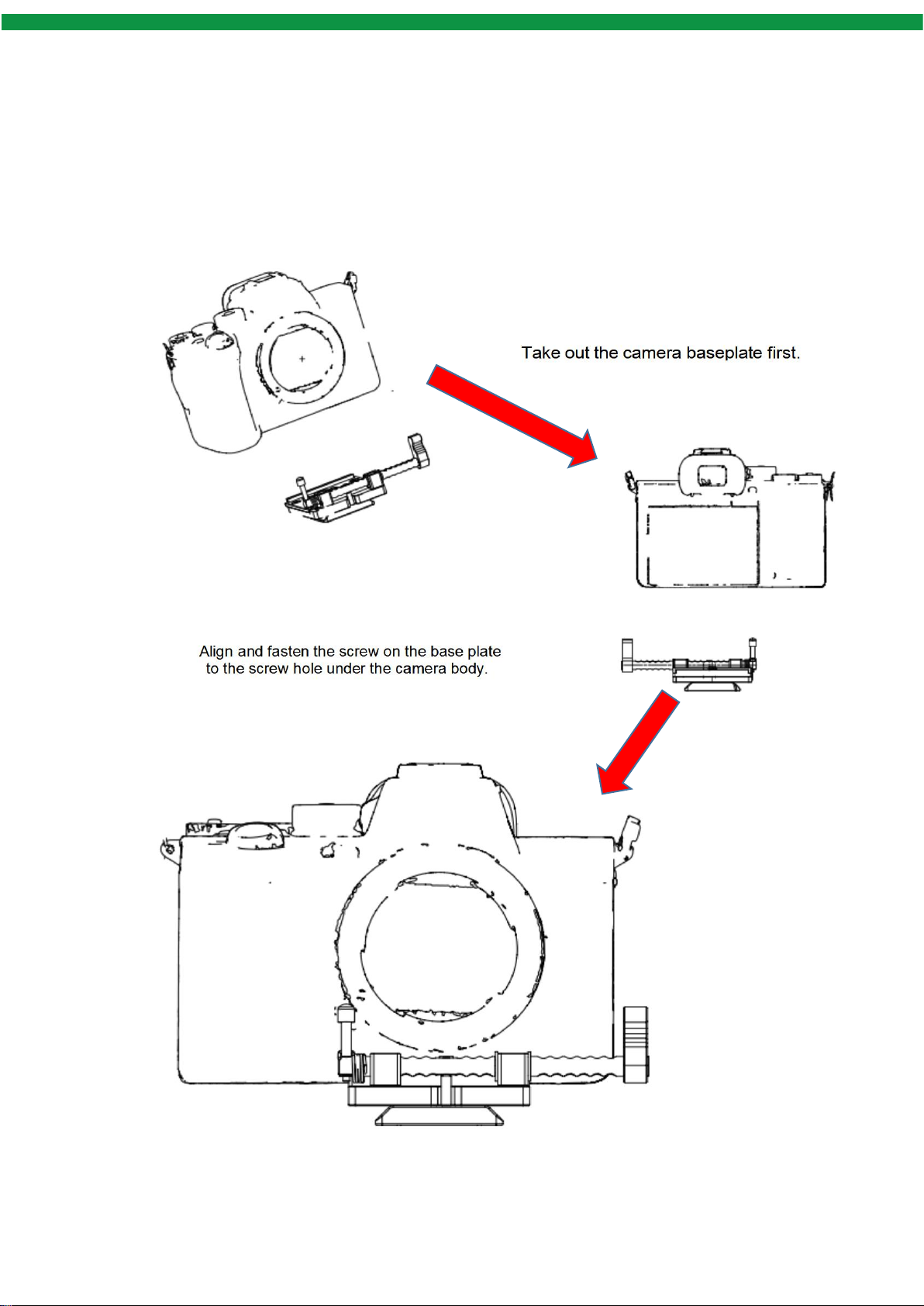
Install Camera

1
8
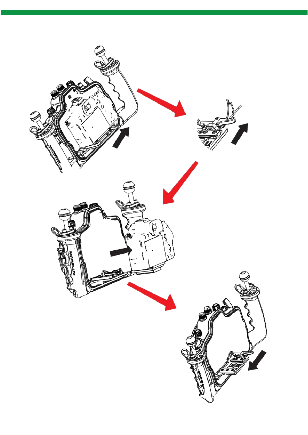
Install Camera
Lock the camera with baseplate
onto the mounting base by
pushing the handle to the left.
the handle to the left to secure it
Align the baseplate below the
camera to the slot on the
mounting base,
and push the camera
Push the handle on the rightside
of the housing mounting base to
the right.
1
9
Remove Camera
Push the handle back to the left
to lock it.
Pull the camera out of the
mounting base.
Push the handle to the right
to release the camera from
the mounting base.
1
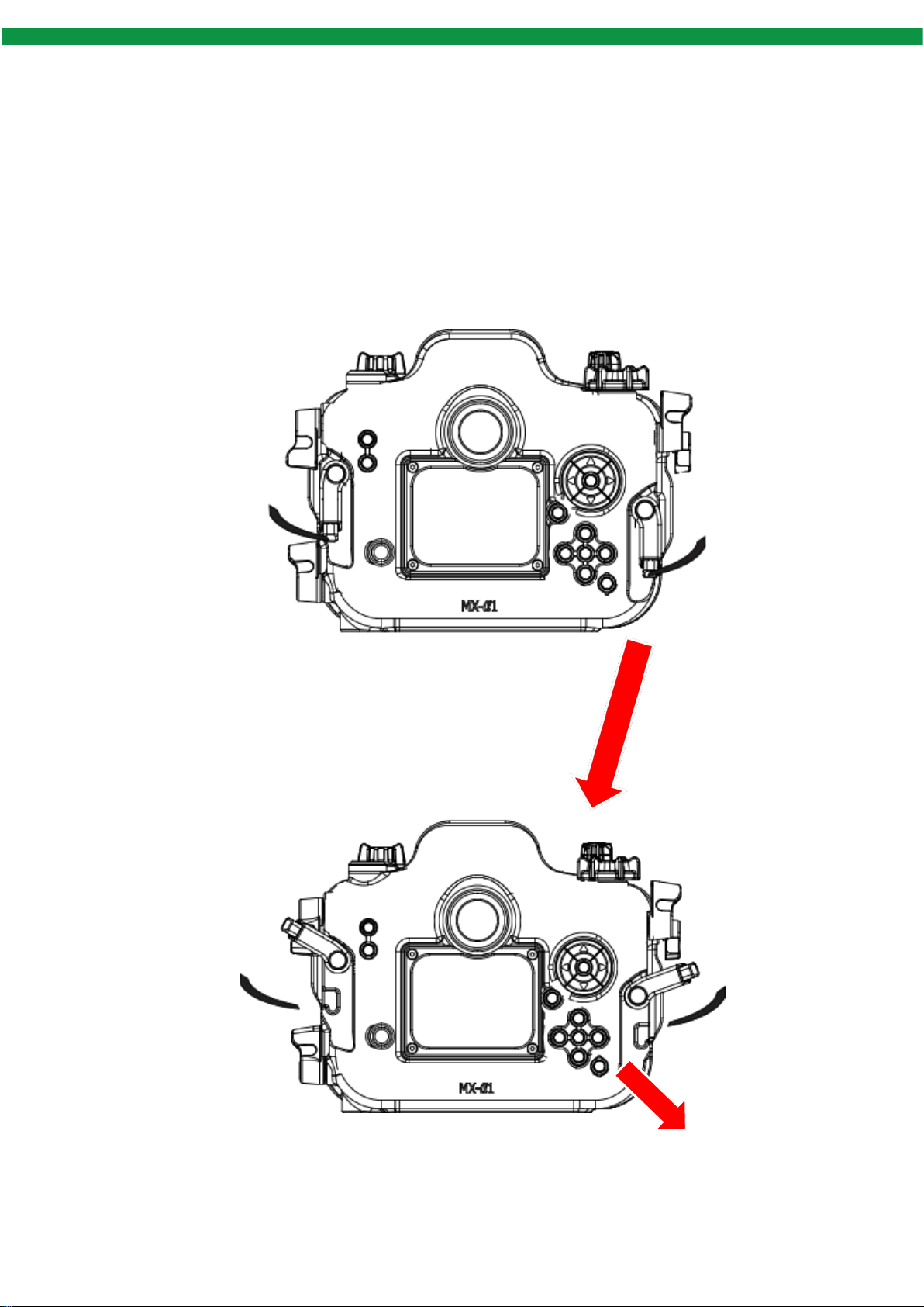
10
Open Housing Body
Caution:
1. Please place the housing body on a flat surface before opening it.
2. Pull up the red knob of the vacuum valve to balance air pressure inside and out side the housing.
Separate back cover from
front cover of the housing with
both hands.
Push the buttons of
security locks on both
sides simultaneously
Push the buttons of
security locks on both
sides simultaneously
Push two knobs
upwards to the end to
release the lock
Push two knobs
upwards to the end to
release the lock
Turn the housing lock
outwards.
Table of contents
Other MARELUX Camera Accessories manuals

MARELUX
MARELUX MX-A7RIII User manual

MARELUX
MARELUX D3 User manual

MARELUX
MARELUX MX-Z6II User manual

MARELUX
MARELUX 45 Degree Viewfinder User manual

MARELUX
MARELUX MX-TG6 User manual

MARELUX
MARELUX MX-RX100M7 User manual

MARELUX
MARELUX Lumilink User manual

MARELUX
MARELUX MX-FX3 User manual

MARELUX
MARELUX MX-R6 User manual

MARELUX
MARELUX MX-A7R5 User manual


Popular Camera Accessories manuals by other brands

Viltrox
Viltrox EF-NEX Mount instructions

Calumet
Calumet 7100 Series CK7114 operating instructions

Ropox
Ropox 4Single Series User manual and installation instructions

Cambo
Cambo Wide DS Digital Series Main operating instructions

Samsung
Samsung SHG-120 Specification sheet

Ryobi
Ryobi BPL-1820 Owner's operating manual


