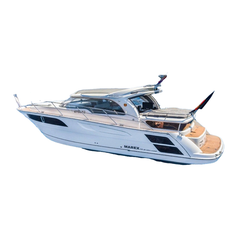
MAREX 373 Aft Cabin Cruiser Instruction Manual

Our quality
Your safety and boat pleasure
You are now the owner of quality product from MAREX. Your boat is
build by the highest standards of safety and quality for your safety and
pleasure.
The handbook is written so that you as a boat owner can have the best
possibilities to get experienced with the boat and its functions. The
handbook contains important information about handling, safety,
systems, equipment mounted or delivered with the boat. You will also
find useful information about use and maintenance.
It is recommended that you make yourself acquainted with the boats
maneuvering ability and properties before you start to use it, regardless
of previous boating experience. Your local dealer can assist you in
finding an instructor or boating school.
Please study the handbook carefully before using the boat.
Producer:
MAREX BOATS UAB
Eglių g. 1,
Ilgakiemio km.
Garliavos sen
Kauno raj
Lithuania
Tlf: 00370 37 26 1500
Fax: 00370 37 26 1700
E-mail sp@marex.lt
MAREX
CONGRATULATES YOU
WITH YOUR NEW
370 AFT CABIN CRUISER (373)

MAREX 373 Aft Cabin Cruiser
LIST OF CONTENTS User handbook chapter 1
Contents Page
ARTICLE I. GENERAL.............................................................................................................. 5
SECTION 1.01 0.1 DIVIDER NR 7. CONTAINS A LIST OF INSTALLED EQUIPMENT IN YOUR BOAT. ... 5
SECTION 1.020.2 SYMBOLS USED IN THE BOOK......................................................................... 6
SECTION 1.03 0.3 CONSTRUCTION CATEGORIES......................................................................... 7
SECTION 1.04 0.4 ABOUT THIS USER HANDBOOK. ...................................................................... 7
ARTICLE II. TECHNICAL DATA ............................................................................................... 8
SECTION 2.01 0.5 GENERAL TECHNICAL DATA........................................................................... 8
SECTION 2.02 0.6 HULL........................................................................................................... 8
SECTION 2.03 0.7 ENGINE AND SHAFT................................................................................... 10
SECTION 2.04 0.8 ELECTRIC SYSTEM....................................................................................... 10
SECTION 2.05 0.9 CAPACITIES ................................................................................................ 10
ARTICLE III. SAFETY............................................................................................................... 11
SECTION 3.01 0.10 GENERAL.................................................................................................. 11
(i) Gas installation and leakage test instruction..................................................................... 12
0.11 FIRE................................................................................................................................... 15
0.1.1 Automatic fire extinguisher ...................................................................... 15
0.1.2 The user/owner is responsible for: .......................................................... 17
SECTION 3.02 0.12 MANUAL LENSING SYSTEM......................................................................... 18
SECTION 3.03 0.13 AUTOMATIC LENSING SYSTEM –ENGINE ROOM............................................ 18
SECTION 3.04 0.14 HULL LEAD-THROUGH UNDER THE WATERLINE........................................... 20
0.1.3 Closing-valve for seawater for the toilet. ................................................. 20
0.1.4 Valve for fresh water................................................................................ 22
SECTION 3.05 0.15 SHORE POWER.......................................................................................... 22
SECTION 3.06 0.16 SAFETY EQUIPMENT .................................................................................. 24
SECTION 3.07 0.17 BATTERIES ............................................................................................... 24
SECTION 3.08 0.18 ENGINE ROOM........................................................................................... 24
SECTION 3.09 0.19 FUEL TANK................................................................................................ 24
SECTION 3.10 0.20 COOKER AND OVEN................................................................................... 25
SECTION 3.11 0.21 EMERGENCY EXITS.................................................................................... 28
SECTION 3.12 CORROSION PROTECTION.................................................................................. 29
ARTICLE IV. DRAWINGS AND TECHNICAL DESCRIPTIONS OF THE BOAT..................... 30
SECTION 4.01 0.22 GENERAL.................................................................................................. 30
SECTION 4.02 0.23 ARRANGEMENT AND EXTERIOR DRAWINGS ................................................. 30
SECTION 4.03 0.24 TECHNICAL SYSTEMS................................................................................. 30
0.1.5 Drawings of the technical systems.......................................................... 30
0.1.6 Pictures and description of installed components................................... 31
SECTION 4.04 0.25 THE FUEL SYSTEM..................................................................................... 31
0.1.7 Common errors........................................................................................ 31
SECTION 4.05 0.26 DRAINING SYSTEM..................................................................................... 32
SECTION 4.06 0.27 LENS PUMP............................................................................................... 33
0.1.8 Common errors........................................................................................ 33
SECTION 4.07 0.28 FRESH WATER SYSTEM.............................................................................. 34

0.1.9 Common errors........................................................................................ 35
SECTION 4.08 0.29 SEPTIC SYSTEM/BLACK WATER SYSTEM .................................................... 35
0.1.10 Common errors...................................................................................... 36
SECTION 4.09 0.30 USE OF THE SEPTIC TANK .......................................................................... 37
SECTION 4.10 0.31 THE ELECTRIC SYSTEM .............................................................................. 38
0.1.11 Maintenance and controlling.................................................................. 40
0.1.12 Common errors...................................................................................... 41
SECTION 4.11 0.32 EXHAUST SYSTEM ..................................................................................... 41
SECTION 4.12 0.33 VENTILATION SYSTEM FOR THE ENGINE ...................................................... 42
SECTION 4.13 0.34 FIRE EXTINGUISHING SYSTEM..................................................................... 42
ARTICLE V. OPERATION........................................................................................................ 43
SECTION 5.01 0.35 STARTING THE ENGINE............................................................................... 44
SECTION 5.02 0.36 BATTERIES (LEAD ACCUMULATORS) .......................................................... 44
SECTION 5.03 0.37 SWITCH PANEL &CONNECTION SCHEMES................................................... 46
SECTION 5.04 0.38 FUSE PANEL.............................................................................................. 46
SECTION 5.05 0.39 MAIN SWITCH PANEL.................................................................................. 47
SECTION 5.06 0.40 WINDSCREEN WIPERS................................................................................ 48
SECTION 5.07 0.41 DASHBOARD INSTRUMENTATION INSTALLATION ACCESS ............................. 48
SECTION 5.08 0.42 MANEUVERING THE BOAT .......................................................................... 49
0.1.13 Maneuvering a boat in category B......................................................... 49
SECTION 5.09 0.43 THE ELECTRIC SYSTEM .............................................................................. 51
SECTION 5.10 0.44 SANITARY SYSTEM .................................................................................... 52
SECTION 5.11 0.45 OPERATING OTHER EQUIPMENT.................................................................. 53
0.1.14 Cooker and oven ................................................................................... 53
0.1.15 The Defroster......................................................................................... 53
0.1.16 The diesel heater................................................................................... 53
SECTION 5.12 0.46 HINTS AND ADVICES .................................................................................. 54
0.1.17 Lifting and storage in a “cradle” ............................................................. 54
0.1.18 Transporting the boat ............................................................................ 54
0.1.19 Mooring the boat.................................................................................... 54
0.1.20 Environmental issues ............................................................................ 55
ARTICLE VI. PERIODIC MAINTENANCE................................................................................ 55
SECTION 6.01 0.47 MAINTENANCE OF THE HULL ...................................................................... 55
0.1.21 Before placing the boat on water........................................................... 55
0.1.22 Before winter storage ............................................................................ 56
0.1.23 Normal maintenance ............................................................................. 56
SECTION 6.02 0.48 MAINTENANCE OF THE TEAK DECK ............................................................. 56
SECTION 6.03 0.49 MAINTENANCE OF THE ENGINE AND THE DRIVE............................................ 56
SECTION 6.04 0.50 MAINTENANCE OF THE STEERING SYSTEM................................................... 57
SECTION 6.05 0.51 FIRE EXTINGUISHERS................................................................................. 57
ARTICLE VII. PREPARING FOR THE SEASON....................................................................... 57
SECTION 7.01 0.52 GENERAL PREPARATION............................................................................ 57
SECTION 7.02 0.53 PREPARING THE ENGINE AND THE DRIVE..................................................... 58
SECTION 7.03 0.54 PREPARING THE STEERING ........................................................................ 58
SECTION 7.04 0.55 OTHER INSTALLATIONS.............................................................................. 58
SECTION 7.05 0.56 REMOVING RUST/CORROSION..................................................................... 59
ARTICLE VIII. WINTER STORAGE PREPARATION................................................................. 60
SECTION 8.01 0.57 BATTERIES ............................................................................................... 60
SECTION 8.02 0.58 THE HULL.................................................................................................. 61
SECTION 8.03 0.59 ENGINE AND DRIVE.................................................................................... 61

SECTION 8.04 0.60 THE STEERING SYSTEM.............................................................................. 61
SECTION 8.05 0.61 WATERLOCK............................................................................................. 62
SECTION 8.06 0.62 EMERGENCY STEERING.............................................................................. 63
SECTION 8.07 0.63 SANITARY SYSTEM .................................................................................... 63
ARTICLE IX. POSITIONS OF THROUGH HULL FITTINGS.................................................... 64
SECTION 9.01 0.64 STARBOARD SIDE...................................................................................... 64
SECTION 9.02 0.65 PORT SIDE ................................................................................................ 65
ARTICLE X. OVERVIEW.......................................................................................................... 66

MAREX 373 Aft Cabin Cruiser
Page 5 of 66
Article I. GENERAL
The handbook is written according to EN-ISO-10240 -
Type : Marex 373 AFT CABIN CRUISER
Construction category : B
Approval : Type approval by Det Norske Veritas,
Type certificate nr. RCD-B-405
See copy enclosed in divider nr 5
The boats CIN number (Craft Identification Number) is engraved aft of the boat,
under the fenderlist starboard side.
Remember to sign for the reception of the user handbook in divider nr. 6!
TAKE CARE OF THE USER HANDBOOK AND KEEP IT FOR THE NEXT
OWNER OF THE BOAT!
Section 1.01 0.1 DIVIDER nr 7. contains a list of installed
equipment in your boat.
The boats CIN number

MAREX 373 Aft Cabin Cruiser
Page 6 of 66
Section 1.02 0.2 Symbols used in the book
(D) DANGER:
The ”D” warnings in the book or in the installed component own user
manual MUST be followed to avoid personal injury or serious material
damage.
(W) WARNING:
The warnings must be followed to avoid damage to boat or equipment.
(C) CAUTION:
This should be remembered to avoid damage to persons or
equipment.
Description:
This is the description of location of the equipment or component.
Instruction Manual:
Read the separate instruction manual/ user handbook for this
equipment. This is placed in the ”User bag” enclosed in the boat.

MAREX 373 Aft Cabin Cruiser
Page 7 of 66
Section 1.03 0.3 Construction categories
EU-directive 94/25/EC’ defines the following categories.
Construction categories:
A. OCEAN: Designed for extended voyages where conditions may exceed
wind force 8 (Beaufort scale) and significant wave heights of 4 m and above,
and vessels largely self-sufficient.
B. OFFSHORE: Designed for offshore voyages where conditions up to, and
including, wind force 8 and significant wave heights up to, and including, 4 m
may be experienced.
C. INSHORE: Designed for voyages in coastal waters, large bays, estuaries,
lakes and rivers where conditions up to, and including, wind force 6 and
significant wave heights up to, and including, 2 m may be experienced.
D. SHELTERED WATERS: Designed for voyages on small lakes, rivers,
and canals where conditions up to, and including, wind force 4 and
significant wave heights up to, and including, 0,5 m may be experienced.
Boats in each Category must be designed and constructed to withstand
these parameters in respect of stability, buoyancy, and other relevant
essential requirements, and to have good handling characteristics.
The actual use of the boat is on own risk. Read all the warnings in the
user manuals.
Section 1.04 0.4 About this user handbook.
This handbook is a part of the documentation that follows the boat. The
handbook as one general part and one specific part intended for your boat only.
Included in the boat is a ”user bag” that contains the handbook and separate
instructions..
This ”user bag” is considered a part of the boat and must be included in the boat
for future owners.
Marex is continuously developing the quality of its products. This book contains
information updated at the time of the print of this book and may therefore
deviate from your boat. Please contact Marex or your local dealer if questions
regarding the user manual should appear..

MAREX 373 Aft Cabin Cruiser
Page 8 of 66
This handbook is adjusted to a standard equipped boat.
Many Marex boats are custom made. Equipment that is not of significant
importance to the safety or stability of the boat is not incorporated in this user
handbook.
Article II. TECHNICAL DATA
Section 2.01 0.5 General Technical data
Boat type : Marex 373 AFT CABIN CRUISER
Construction category : B
Section 2.02 0.6 HULL
Type
Measurement
Metric
Line
Length over all incl/ bowsprit and platform (LOA)
11301
cm
Length hull waterline (LW)
898
cm *)
Transport height without lantern mast and mounted
extra equipment (Transport height excluding the rudder)
341
cm *)
Transport height without lantern mast and mounted
extra equipment (Transport height including the rudder)
368
cm
Total height from bottom to top lantern mast including
flagpole.
424
cm *)
Height from the waterline (Sailing height) with lantern
mast including flag pole
370
cm *)
Height from the waterline (Sailing height) without
lantern mast, excluding flagpole
341
cm *)
Height from the hulls keel to the top of the lantern mast
including top lantern
424
cm
Height of the mounted and removable lantern mast
83
cm
Marex cradle height
10
cm
Beam excluding fender list BOA
350
cm
Beam including fender list BOA
355
cm
Beam of the boat waterline BW
306
cm

MAREX 373 Aft Cabin Cruiser
Page 9 of 66
Displacement of empty boat single engine
6400
ca.
kg*)
cm* / kg*) standard boat and weight according to single Volvo D6 –435

MAREX 373 Aft Cabin Cruiser
Page 10 of 66
Section 2.03 0.7 Engine and SHAFT
Engine type : Marine diesel, single shaft (Seatorque or
Clements).
Max recommended effect
Single engine : 320kW (435 Hp)
Section 2.04 0.8 Electric system
Voltage : 12V DC/220V AC
Starter battery : 100 Ah
Service batteries : 4 x 100 Ah
Section 2.05 0.9 Capacities
Fuel tank : 660 liters
Water tank : 385 liters
Septic tank : 120 liters
Lens pump - Manual :
Engine room : 0,5 liter per stroke
Front cabin : 0,5 liters per stroke
Lens pump - Electric:
Engine room : max 70 liter/min
Front cabin : max 70 liter/min
Max ship weight incl. 8 Persons,
Full tanks and luggage : 7700kg
Max load incl. 8
Persons and luggage
(As shown on the producer plate) : 1000 kg
Max recommended number of persons: 8 persons
WARNING —Do not exceed the maximum recommended number of persons.
Regardless of the number of persons on board, the total weight of persons and equipment
must never exceed the maximum recommended load. Always use the seats/seating spaces
provided.
When loading the craft, never exceed the maximum recommended load. Always
load the craft carefully and distribute loads appropriately to maintain design trim
(approximately level). Avoid placing heavy weights high up.

MAREX 373 Aft Cabin Cruiser
Page 11 of 66
Article III. SAFETY
We summarize the important information for safety aboard. A great deal of the
information will be repeated later in the user manual, but Marex signify the
importance for you as a customer and user of the boat that this information is
easy accessible in a stressed situation.
What’s described should be studied by the customer:
Section 3.01 0.10 General
(W) WARNING
Never:
let objects block the emergency exits –doors and hatches
let objects hinder access to the fuel stop valve, lens pumps and
electrical switches..
let objects hinder access to fire extinguishers.
use gas lights
change any of the boats technical systems –specially the gas fuel and
electrical systems.
fill the fuel tank while the engine is running or while the cooker or
heater is in use.
smoke when handling fuel
use the rails to pull anything after the boat. Never use the rails as
mooring.
place fenders at the exhaust outlets for heater and cooker.
Always:
inspect the boat in particular the engine room for leakages before every
turning on the engine.
have cabin doors closed during sailing. The weight of the doors can
make the doors slam. Also close all portlights and windows during
rough weather conditions, or while planing.
keep lensing pump free from impurities.
check for leakage or incomplete combustion or smoke from the fuel
system,
check fuel level.

MAREX 373 Aft Cabin Cruiser
Page 12 of 66
(i) Gas installation and leakage test instruction
READ THE INSTRUCTIONS CAREFULLY BEFORE THE LEAK
DETECTOR IS INSTALLED OR USED!
Used symbols:
1.0 SAFETY
WARNING! I DANGER!
The leak detector is designed for indicating leaks in L.P.G.- systems with a maximum
working pressure of 200 kPa (2 bar).The system is supposed to be checked prior to the
first time use, after a period of non-use and always when the gas bottle is changed.
L.P.G. is an explosive gas, therefore smoking and open flames are absolutely prohibited
when the detector is being installed or used.It is also recommended to make the
function and use of the leak detector well known to all users of the L.P.G. installation.
See section 3.1 O!
2.0 INSTALLATION
2.1 We assume that the leak detector has been chosen to fit the connections and tubing
of the L.P.G. installation.
2.2 Close the main valve on the gas bottle or dismount the regulator.
2.3 The leak detector has to be mounted in a vertical position after the regulator in the
same space as the gas bottle or bottles are stored. Make sure that the sight glass
is in full view. Stainless steel screws are included in the mounting kit (Fig. 2a).
2.4 Note the flow direction of the gas, marked with an arrow on the detector.
2.5 IMPORTANT! When connecting cupper tubing (8,O x 0,8 mm), the enclosed
reinforcement sleeves have to be used (Fig. 2b). Hold the fitting with a spanner
when tightening the nut with a second spanner. 2.6 When connecting hoses,
hoses with prefabricated end fittings are recommended, and a must in boat
installations according to IS0 10239 (EN 1763-1 and EN 1763-2). CE-marking
from. July 1998. Other installations still allows hose clamps. If hose clamps are
used, they should be the kind of hose clamps used for fuel hoses in stainless
steel.
2.7 Unscrew the sight glass turning it counter-clockwise (Fig. 2c).
2.8 Fill up the sight glass till the marking on the glass (Fig. 2d).
2.9 Screw the sight glass back turning it clockwise by hand (Fig. 2e).
The leak detector is now ready for use.
3.0 TESTING
3.1 Fit the regulator and open the main bottle valve
3.2 Open the valves supplying the stove, the oven, the fridge and the heater, without
activating the ignition safety devices.
3.3 Press and hold the red button for approx. 10 seconds (Fig. 3a).
3.4 If no bubbles appear in the sight glass, the system is leak tight up to the individual
maneuver switch or valve of the installed device (Fig. 3b).
3.5 If bubbles appear in the glass the system is leaking (Fig. 3c)!
3.6 Release the red button and locate the leakage (Fig. 3d).
3.7 Close all the valves to the individual equipment (stove, oven, fridge and heater) and
check according to 3.3. If there still are bubbles in the sight glass when pressing
the red button, there is a leakage between the leak detector and the valves.
Locate the leakage using a leak spray, soapy water (without ammonia) or an
electronic leak tester and repair the leakage. Leaking tube fittings and hose

MAREX 373 Aft Cabin Cruiser
Page 13 of 66
connections are fixed through tightening the nuts and hose clamps. If this doesn't
cure the problem - change hoses and fittings.
3.8 If the leakage can't be traced to the tubes and hoses, open up the valves to the
equipment one by one. Start by testing the hose connection between the valve
and the equipment. If the leakage can't be found here, there is a leakage in the
equipment (stove, oven etc.). If so contact a gas expert, to have the equipment
repaired and tested at 15 kPa (150 mbar).
3.9 Check again in accordance with 3.1 - 3.4.
3.10 To demonstrate the function and to test the detector turn one of the
burners on the stove on, and let it burn on low power. This simulates a leakage in the
system. Press and hold the red button on the leak detector. The bubbles now
appearing in the sight glass shows that the system is leaking (simulated by the
burning flame).
It is absolutely prohibited to use a leaking L.P.G. system!
Close the main valve till the leakage has been repaired!
By uncertainty - contact a professional, testing the system at
maximum 15 kPa (150 mbar).
GB - INSTRUCTIONS
4.0 EQUIPMENT WITH IGNITION SAFETY DEVICE
4.1 The leak detector can also be used for testing the ignition safety
device of the equipment. Two persons are required.
4.2 Turn on for instance a burner and let it burn on low power.
4.3 Press and hold the red button on the leak detector. It is now bubbling in the sight
glass constantly.
4.4 Blow out the burner and after 10 to 30 seconds the bubbling in the sight glass
should stop. If more than 60 seconds are required an expert has to be contacted.
5.0 REPAIRS I MAINTENANCE
5.1 The leak detector is virtually maintenance free. If the fluid level should drop below
the level mark propylene glycol must be refilled (Fig. 2c.).
6.0 WARRANTY
6.1 As per our current warranty regulations.
7.0 DISPOSAL AND RECYCLING
7.1 When the leak detector is not supposed to be used anymore, it has to be disposed
following the local environmental regulations. The leak detector 100 4000 is
approved by the Danish Governmental Gas Institute DGP (Notified Body for CE
approvals) Approval number DG-3795.

MAREX 373 Aft Cabin Cruiser
Page 14 of 66

MAREX 373 Aft Cabin Cruiser
Page 15 of 66
0.11 Fire
(D) 1 manual fire extinguisher 2 kg type ABC class II (powder
apparatus) located:
Cockpit, next to entrance to front cabin
The engine room has an automatic fire extinguisher system
with auto discharge and auto stop of the engine. This extinguisher
has an indicator in the dashboard.
All fire extinguishers must be checked yearly by qualified personnel. Read
the instructions at the apparatus and be prepared for an emergency
(W) Do not mount curtains or other fabrics over or close to any cooker or open flame
sources.
(W) Flammable material must not be stored in the engine room. If non-flammable
material is kept in the engine room it must not block access or risk contact with
the engine
0.1.1 Automatic fire extinguisher
Read the manual for Sea-Fire, enclosed in the “user bag”.
Vessels with engines larger than 120 kW (163 Hp) is equipped with a permanent
fire extinguisher in the engine room. The fire extinguisher has automatic
discharge by temperatures over 74o C. Indicator by the pilots position informs if
the extinguisher has been discharged. The engine (s) will be stopped
automatically. When the ignition is on the lamp indicator will light as long as the
system is ready to be discharged. After a discharge the lamp will no longer light.
*) Sea-Fire display may deviate from what is mounted in the boat.
Indicator lamp

MAREX 373 Aft Cabin Cruiser
Page 16 of 66
(C) Your boat has automatic fire extinguishing system in the engine room that uses
FM200 as an active component.
The engine room has a fixed installed system. The contents can cause
serious respiration problems and be fatal.
Automatic fire extinguishing system in the engine
room shown with a temperature sensor.
Indicator lamp

MAREX 373 Aft Cabin Cruiser
Page 17 of 66
By automatic discharge of the contents,
The engine stops automatically!
Turn of the main switches.
Evacuate the cabins.
Grab the manual fire extinguisher and release the safety pin.
Control the engine room for fire.
Let the automatic extinguisher work for several minutes.
By opening of the engine hatches, have the manual extinguisher ready
and be alert.
After discharge always ventilate before entering the engine room
By fire out of control:
Take on the emergency vests.
Send emergency signals by radio or chart plotter, signal lights or
telephone.
Evacuate the boat.
(W) See the separate manual in the”User bag”. Do not lift or transport the
extinguisher in the sensor valve. Do not drop the extinguisher. Keep the
extinguisher out of reach for children.
After a discharge- REPLACE the cylinder.
0.1.2 The user/owner is responsible for:
That the extinguisher is controlled by qualified personnel at recommended times.
That the extinguisher is replaced with working equipment.
Inform the passengers about:
location and use of the fire extinguishers
location the emergency exits
Assure that fire extinguishers are easy accessible.

MAREX 373 Aft Cabin Cruiser
Page 18 of 66
Section 3.02 0.12 Manual lensing system
The manual lensing system pumps out the water by hand. This system is used
when the automatic system cannot be used or when you need to lens the tank
room or cabin.
Two lens pumps are placed on the aft deck, in the portside wall.
The lens pump pumps the water out of the room the arrow is pointed at..
One lens pump lenses the “engine room” and the aft cabin
The second position of the valve lenses the front cabin
Stick the “pin” (a steel rod with a black handgrip) and pump up and down.
Section 3.03 0.13 Automatic lensing system –Engine room
In addition to the manual lensing there is the automatic system. This system
works for the engine room, the aft cabin and for the front cabin. This is important
to know. The auto-lensing is connected to a switch on the dashboard.
Switches are located in dashboard under the steering wheel
Then switches are operated manually symbol lights up. .
If pump starts working automatically symbol, lights up too.

MAREX 373 Aft Cabin Cruiser
Page 19 of 66
To test the pump: open floor hatch and check
if the red diode is turned on and
The summing tone is coming from the opened engine room
If both points are ok, the switch appears to be in order.
SAFETY PRECAUTION —Check the function of all bilge pumps at regular
intervals. Clear pump inlets from debris and garbage.
WARNING
Automatic lens-pump does not replace a visual control.
Automatic lensing does not work if the batteries have a lower voltage
than 11 Volt.
Switches for the electric lensing
pump
Front automatic bilge pump and front
intake for manual bilge pump

MAREX 373 Aft Cabin Cruiser
Page 20 of 66
Section 3.04 0.14 Hull lead- through under the waterline
0.1.3 Closing-valve for seawater for the toilet.
(see enclosed drawing.. B.02.01)
The closing valves placed under the floor in the engine room.
Close Septic discharge valve then emptying the septic tank through deck fitting.
The crane is placed in the engine room
(W) Parallel with the hose: open:
When the valve handle is a cross the hose it is closed:
Valve for discharging
the septic
Valve for engine
cooling water intake
Table of contents
Other MAREX Boat manuals
Popular Boat manuals by other brands

Wilderness Systems
Wilderness Systems 2009 owner's manual

Boston Whaler
Boston Whaler 320 Outrage owner's manual

Chaparral
Chaparral 225 SSi2012 Owner's and operator's manual

Zodiac
Zodiac MilPro ERB 310 owner's manual

Creek Company
Creek Company ODC XR 10 Assembly instructions

Toyota
Toyota Epic 21 Closed Bow owner's manual