Marilyn DAR-01 User manual

DAR-01 Rev. D
User’s Manual
Release Date 03/31/2015


Table Of Contents
Table of Contents
Introduction ........................................................................................................................................ 1
Disclaimer.............................................................................................................................................................................. 1
Warranty................................................................................................................................................................................ 1
Use and Care ....................................................................................................................................................................... 1
Contact Information ........................................................................................................................................................... 1
Overview ............................................................................................................................................. 2
Device Layout ...................................................................................................................................... 3
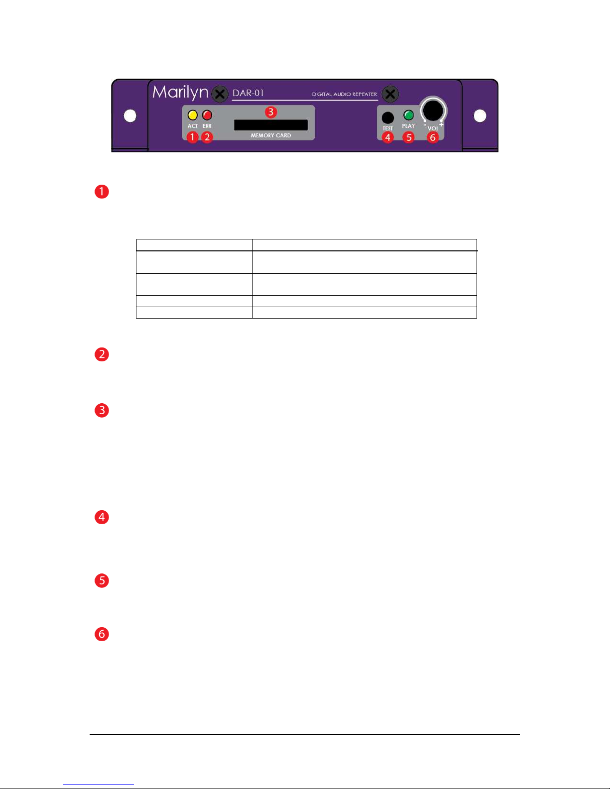
Front Panel............................................................................................................................................................................ 3
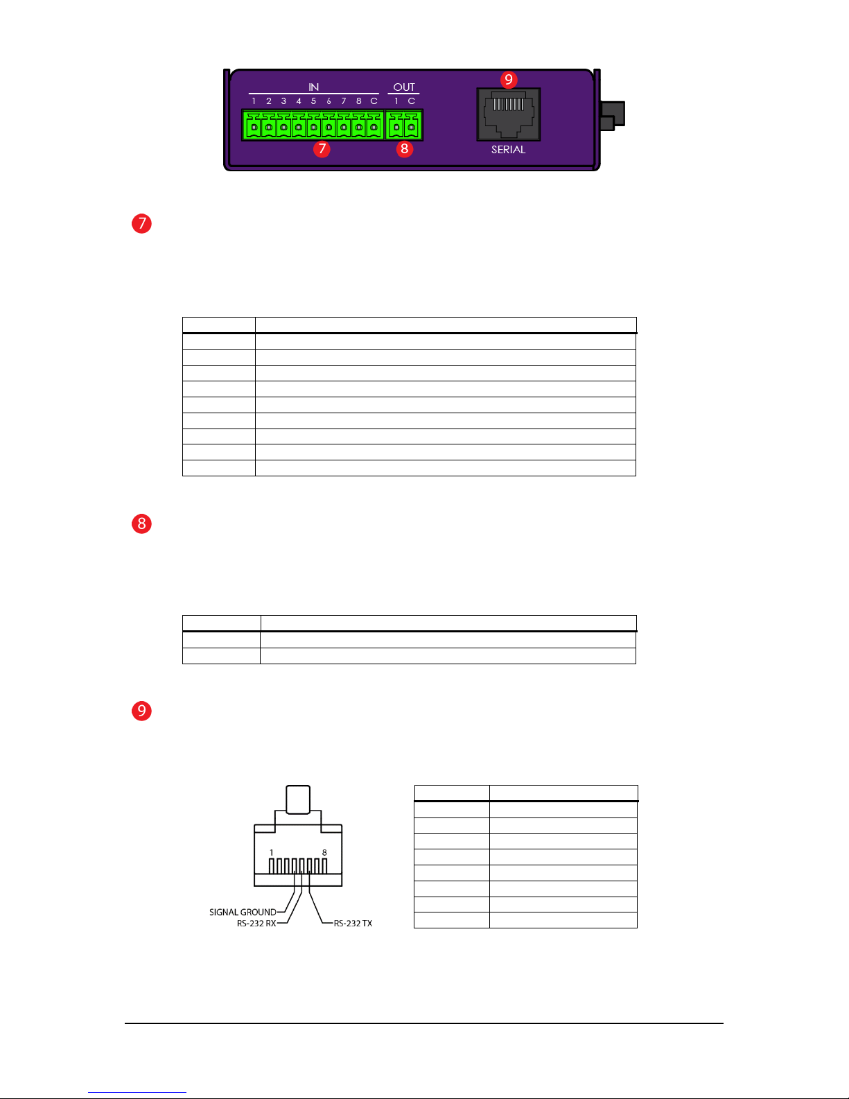
Left Panel .............................................................................................................................................................................. 4
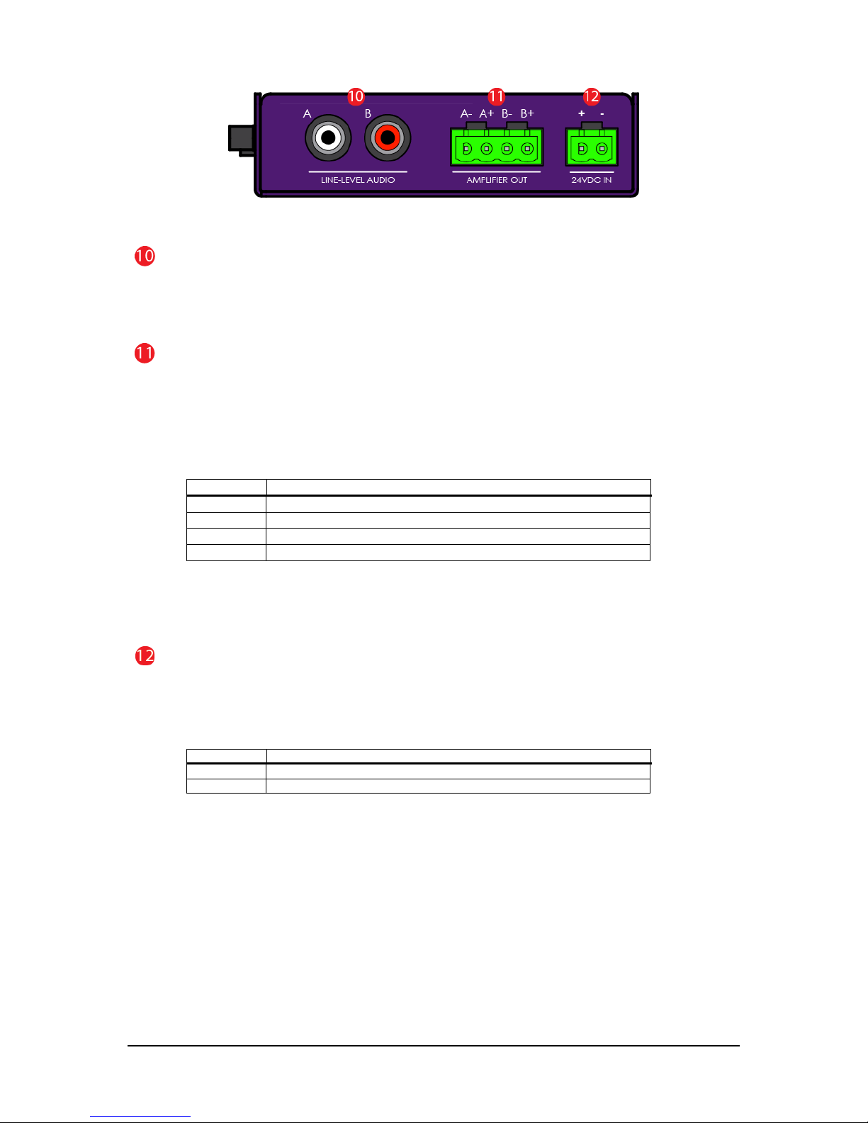
Right Panel............................................................................................................................................................................ 5
Wiring E amples .................................................................................................................................. 6
Power..................................................................................................................................................................................... 6
Speakers-stereo ................................................................................................................................................................... 7
Speakers-mono.................................................................................................................................................................... 7
Inputs with negative common .......................................................................................................................................... 8
Inputs with positive common............................................................................................................................................. 8
Outputs with negative common....................................................................................................................................... 9
Outputs with positive common ......................................................................................................................................... 9
Serial to PC.......................................................................................................................................................................... 10
Serial to Other Marilyn Systems Equipment ................................................................................................................... 10
File Names ........................................................................................................................................ 11
Configuration File ............................................................................................................................... 12
INI file overview .................................................................................................................................................................. 12
[StartUp] Section................................................................................................................................................................ 13
[Audio] Section .................................................................................................................................................................. 14
[Serial] Section.................................................................................................................................................................... 15
[Input] Section.................................................................................................................................................................... 16
[InputxMake] Section........................................................................................................................................................ 17
[InputxBreak] Section ........................................................................................................................................................ 18
[ButtonMake] Section ....................................................................................................................................................... 19
[ButtonPress] Section......................................................................................................................................................... 20
[ButtonBreak] Section ....................................................................................................................................................... 21
[ButtonRelease] Section ................................................................................................................................................... 22
[UserPot] Section................................................................................................................................................................ 23
[VolumeControl] Section.................................................................................................................................................. 23
[UserLed] Section............................................................................................................................................................... 24
[PlayLed] Section............................................................................................................................................................... 24
[StatusOutput] Section...................................................................................................................................................... 24
Button Make, Button Break, VolumeControl, PlayLed, and StatusOutput E amples .................................. 25
Configuration File Application E amples ............................................................................................... 26
CONFIG.001........................................................................................................................................................................ 26
CONFIG.002........................................................................................................................................................................ 27
CONFIG.003........................................................................................................................................................................ 28
CONFIG.004........................................................................................................................................................................ 29
ASCII Serial Protocol .......................................................................................................................... 30
Firmware Upgrade ............................................................................................................................. 31
Techical Specification ......................................................................................................................... 32
Mechanical Drawings .......................................................................................................................... 33

2015, Marilyn Systems, llc.
1

2
2015, Marilyn Systems, llc.
Introduction
Thank you for purchasing the DAR-01 digital audio repeater. This rugged, versatile, player
should provide years of reliable service. The following user manual will provide the information
needed to install and use this device.
Disclaimer
Marilyn Systems equipment is neither designed nor intended for use in safety critical
applications where the potential for personal injury or property damage is present. The
customer assumes full responsibility and liability for any consequences arising from such use.
Marilyn Systems, llc. makes no assertion that this product is suitable for any specific
application and will not be held responsible or liable in any way for improper use.
Marilyn Systems strives to ensure the accuracy of the information provided in this manual.
Should you find an error, please bring it to our attention so that we may correct it in a future
revision.
Warranty
Unless stated otherwise, all products manufactured by Marilyn Systems are warranted to be
free from defects in material and workmanship for a period of one year from date of
purchase. Products that fail during the warranty period will be repaired or replaced at the
discretion of Marilyn Systems.
The warranty does not cover return shipping charges to Marilyn Systems or physical product
damage due to improper configuration or application, abuse, accidents, or shipping damage.
Marilyn Systems will however cover reasonable return shipping charges for products repaired
or replaced under the conditions of this warranty.
All products manufactured by others and sold as such by Marilyn Systems shall be governed
by the terms of said manufacturer’s warranty.
Use and Care
The DAR-01 should be mounted securely a clean, dry environment with an operating
temperature range of 0
ο
to 38
ο
C (32
ο
to 100
ο
F). Always operate the DAR-01 within specified
parameters. Clean with a soft, damp cloth.
Customer Support
You may contact Marilyn Systems for technical or service support by phone or email:
Phone: 210.200.8451 between the hours of 9am-6pm Central Standard Time
Fa : 210.200.8487
Email: support@marilynsystems.com
www.marilynsystems.com
Marilyn Systems, llc.
12915 Agency
San Antonio, Te as 78247

2015, Marilyn Systems, llc.
3
Device Overview
The DAR-01 is a solid-state device that plays MP3 and WAV audio files. It can directly drive
loudspeakers with a powerful, built-in amplifier, or, it can be interfaced to an e ternal audio
system using the line-level outputs.
Up to 500 audio tracks are stored on an SD or SDHC flash memory card and called up using
the eight optically-isolated inputs, the serial port, or internally. A simple, plain-English
configuration file allows the user the fle ibility to modify all operating parameters to suit their
needs. Being a standard te t file, the user needs only a te t editor on the platform of their
choice to quickly make configuration changes - no specialized software is required. A
convenient user interface consisting of various status LEDs, a test button, and a volume control
potentiometer are present on the front of the unit. A solid-state relay output provides devices
status.
Out of the bo , the DAR-01 can be surface or edge mounted. An optional DIN-rail mount kit is
available for standardized integration into industrial panels. A card-guard kit is also available to
prevent card removal.
Updating the firmware on the DAR-01 is a snap and ensures that you always have the newest
features. The latest firmware is always available on our website at www.marilynsystems.com.
The Revision D DAR-01 is differentiated from its predecessors by:
•A more powerful, 80-Watt amplifier
•An RS-232 serial interface replaces the RS-485 port found on previous models. This
version had a single RJ-45 jack as opposed to two.
•The volume control now has a knob rather than being recessed
•Unique silkscreen graphics.

4
2015, Marilyn Systems, llc.
Unit Layout
Figure 1 – Front View
ACTivity Indicator
The yellow ACT indicator shows both the current state of the player and any occurring activity.
Indication Function
Slow blink No flash card inserted or no usable configuration
file/media found on the card
Fast blink DAR-01 is reading the configuration file and analyzing
any media present on the flash card
short flash every second Unit is operating normally
½-second flash Indicates input or serial activity
Table 1
ERRor Indicator
The red ERR indicator lights when an issue is present.
MEMORY CARD slot
All sound files and configuration information are stored a SD or SDHC flash memory card. The card is
inserted by gently pushing it into the socket, with the contacts down and towards the DAR-01, until a “click”
is heard. To remove the card, push it in slightly until a “click” is heard. The card is now unlocked and will
be ejected from the socket.
If you wish to prevent removal of the card, an optional guard cover is available.
TEST button
This momentary pushbutton switch provides a user-programmable means of testing the unit. Please refer to
the configuration section for more details.
PLAY LED
The red PLAY indicator lights to indicate that the unit is playing audio
VOLume Potentiometer
This programmable potentiometer provides control over upper and lower limits or can be disabled. Please
refer to the configuration section for more details.

2015, Marilyn Systems, llc.
5
Figure 2 – Left View
INputs Connector
Eight non-polarized, optically-isolated inputs are available for triggering tracks and performing other actions.
The entire group shares a single common. The inputs can accept 12-24VDC and draw a ma imum of 10mA.
Please refer to figures 7 & 8 for wiring e amples.
Terminal Function
1 Input 1
2 Input 2
3 Input 3
4 Input 4
5 Input 5
6 Input 6
7 Input 7
8 Input 8
C Input Common
Table 2
OUTput Connector
A solid-state relay output is available for various functions. This relay can switch 100mA at 24VDC, enough
to drive a typical electromechanical relay, lamp, or other similar device. Please refer to figures 9 & 10 for
wiring e amples.
Terminal Function
C Status output common contact
NO Status output normally-open contact
Table 3
SERIAL Connector
RS-232 port brought out on an EIA-561 compatible RJ-45 jack. See configuration file section for serial port
operating parameters.
Terminal Function
1 NC
2 NC
3 NC
4 Signal Ground
5 DAR-01 R
6 DAR-01 T
7 Reserved
8 NC
Pin-out (cable-end, connector front) Table 4

6
2015, Marilyn Systems, llc.
Figure 3 – Right View
LINE-LEVEL AUDIO Jacks
Two RCA, line-level output jacks marked A (left) and B (right) are provided for connection to an e ternal
audio system. These outputs are always active regardless of the state of the amplifier.
AMPLIFIER OUT Connector
A 40W-per-channel, stereo amplifier which can directly drive a 4 to 8-ohm loudspeaker load (see figure 5).
Optionally, the outputs may be paralleled for a single, 80W output by jumping together both positive
terminals and both negative terminals respectively (see figure 6 for a wiring e ample). PLEASE NOTE that
a mono audio file
must
be used when the outputs are paralleled. The amplifier can be disabled if it will
not be used. Please refer to the configuration information below for more details.
Terminal Function
A- Channel A (left) negative terminal
A+ Channel A (left) positive terminal
B- Channel B (right) negative terminal
B+ Channel B (right) positive terminal
Table 5
If you are upgrading from a rev. b or rev. c DAR-01, please notice that the amplifier output pin-outs
have changed.
24VDC IN Connector
The DAR-01 can operate on a little as 12VDC however for optimal amplifier performance, 24VDC should be
provided. With the amplifier enabled, a minimum 100Watt supply should be used.
Do not
use an
unregulated supply as this could damage the player. See figure 4 for a wiring e ample.
Terminal
Function
+
Power supply positive
-
Power supply ground
Table 6

2015, Marilyn Systems, llc.
7
Power Wiring Example
Figure 4 – Power wiring example

8
2015, Marilyn Systems, llc.
Speaker Wiring Examples
Figure 5 – Stereo speaker wiring example
Figure 6 – Mono speaker wiring example (amp paralleled)

2015, Marilyn Systems, llc.
9
Input Wiring Examples
Figure 7 – Inputs with negative common wiring example
Figure 8 – Inputs with positive common wiring example

10
2015, Marilyn Systems, llc.
Output Wiring Examples
Figure 9 – Output with negative common wiring example
Figure 10 – Output with positive common wiring example

2015, Marilyn Systems, llc.
11
Serial Port Wiring Examples
Figure 11 – DAR-01 to computer RS-232 serial port wiring
Figure 12 – DAR-01 to other EIA-561 serial device wiring

12
2015, Marilyn Systems, llc.
File Names
All DAR-01 files are named in the standard 8.3 format. This consists of an eight-character file name and a
three-character e tension separated by a ‘.’ period. All upper-case characters should be used.
Example:
FILENAME.EXT Is a valid 8.3 file name.
Filename.Ext Is not.
Audio files on the DAR-01 must be named in a very specific format so that the unit can find and access
them. The first 5 characters of the filename are always ‘SOUND’ followed by a 3-digit decimal number
representing the track number. This number shall be in the range of ‘001’ to ‘500’ to represent the track
number. All leading zeros must be present. MP3 sound files will always have an ‘MP3’ e tension and
WAV files will always have a ‘WAV’ e tention. It is important to keep these e tensions straight as the
audio will not play correctly for incorrectly named files. Numbers cannot overlap between MP3 and WAV
files meaning that there cannot be SOUND001.MP3 and SOUND001.WAV on the same card.
Example:
SOUND001.MP3 An MP3 file which will be referred to simply as “1” within the player.
SOUND255.WAV Track 255 is a WAV file.

2015, Marilyn Systems, llc.
13
Configuration File
The DAR-01 configuration file specifies all operating parameters for the player. A simple te t format
allows for editing from any computer or operating system.
This file must be named CONFIG.TXT so that the player can find it on startup.
The configuration file for the DAR-01 is based on the standard INI file format.
Each operating parameter of the DAR-01 consists of a name and value separated by an equal sign (=).
name = value
Parameters are grouped by section. The section name appears on its own line in square brackets.
[section]
Comments may be added and are preceded with a semicolon. Comments are for documentation
purposes only and are ignored by the DAR-01.
; comment text
Please note: Default values are assumed on all parameters if the parameter is not
defined or defined incorrectly.

14
2015, Marilyn Systems, llc.
[Startup] section
The Startup section defines the behavior of the DAR-01 immediately after power-up or card insertion.
Startup section parameters:
Action - Describes what the player should do when powered up.
Value Function
DoNothing Take no action (Default)
Play Play the specified track(s).
PlayToEnd Plays the specified track(s) uninterrupted.
Loop Loops the specified track(s).
BGM BGM mode. In BGM mode, the selected tracks are played in a
sequential loop. Whenever another event is triggered, the current BGM
track is paused until the end of the interrupting track at which time the
BGM track resumes. Using the FadeRate allows for the BGM track to
fade back in slowly. Stop is the only event that can stop BGM mode.
Table 7
FirstTrack Specifies the first track to be played by the startup action. Must be an integer in the
range of 1-500. This number corresponds to the three-digit number in the file name of an audio track.
LastTrack Specifies the last track to be played by the startup action. Must be an integer in the range
of 1-500. LastTrack must be greater than or equal to FirstTrack.
Retentive – Track count is retained for this action when enabled.
Value Function
Yes Do not retain track count (Default).
No Retain track count.
Table 8
Volume – Volume level for this action. 0-100%. If this is not defined, the volume will not be affected.
FadeRate – Defines how long the volume should take to ramp from the current level to the new level
defined by this action. 10mS increments (10= 1 second). If zero, then no fade occurs. Zero is default.
No fade if volume is not defined.
Example:
; In this example, we will loop tracks 1 through 5 at
; full volume on startup
[Startup]
Action= Loop
FirstTrack= 1
LastTrack= 5
Volume= 100
FadeRate= 0

2015, Marilyn Systems, llc.
15
[Audio] Section
Describes the audio configuration of the player.
Audio section parameters:
AmpEnabled - Enable or disable the built in amplifier.
Value Function
Yes Amp is enabled
No Amp is disabled (default)
Table 9
AmpBoost When enabled (Yes), the audio signal gain is boosted to provide full power to 8-ohm
speaker loads. Make sure to disable this if you are using 4-ohm speakers as the amplifiers may shut
down to prevent damage.
Value Function
Yes Amp gain boost is enabled – 8-ohm speakers attached
No Amp gain boost is disabled (default) 4-ohm speakers attached
Table 10
Example:
; Enable the internal amplifier with amp boost
[Audio]
AmpEnabled=Yes
AmpBoost=Yes
; In this example, we disable the amplifier. Note that this is not
; necessary as parameters assigned to their default values do not
; need to be specified in the configuration file.
[Audio]
AmpEnabled=No
AmpBoost= No

16
2015, Marilyn Systems, llc.
[Serial] Section
Configure the serial communication port.
Serial section parameters:
Mode - Defines the operating mode of the serial port
Value Function
Disabled The serial port is not used (default)
ASCII The unit will respond to plain-te t commands. No parity, 8-bit
character, 1 stop bit. Baud rate is user defined.
Table 11
BaudRate - Defines which baud rate to use. This parameter will be ignored if the serial port is
disabled. Available baud rates are:
Value Function
300 Serial port operates at 300 baud.
600 600 baud
1200 1200 baud
2400 2400 baud
4800 4800 baud
9600 9600 baud (default)
19200 19.2k baud
31250 31.25k baud
36400 36.4k baud
57600 57.6k baud
115200 115.2k baud
250000 250k baud
Table 12
SerialAddress-
Defines the serial communications address this device will respond to. This number
must be in the range of 1 to 254 and if not defined, the DAR-01 will respond to all serial messages.
This parameter will be ignored if the serial port is disabled. Note that this not currently used but left in
for compatibility with previous models.
Example:
; Enable the serial port for ASCII operation at 9600 Baud.
; Note that we do not specify the baud rate as we are using
; the default value.
[Serial]
Mode=ASCII
; Enable the serial port for ASCII operation at 57.6Kbaud.
[Serial]
Mode=ASCII
BaudRate=57600

2015, Marilyn Systems, llc.
17
[Inputs] Section
Defines how the device will respond to the optically-isolated inputs.
Inputs section parameters:
Mode Sets the general operating mode of the inputs.
Value Function
Individual The function of each input can be independently defined (default)
Table 12
Eg.
; Inputs operate individually
[Inputs]
Mode=Individual
Table of contents
Other Marilyn Repeater manuals