MARINE PROPELLER JPROP Manual

ELICHE A PASSO VARIABILE
Manuale d’uso e manutenzione
VARIABLE PITCH PROPELLERS
Use and maintenance handbook

Congratulations on choosing the new "JPROP" propeller !
We are pleased to give you some general information and the
technical instructions for its assembly, use and servicing.
• "JPROP" has been created by the twenty-years experience of
Cober, a precision mechanical industry which as come famous
in its field. Every detail is built with the best materials and
processed on CNC working centre.
• Thanks to its vast range of sizes and to its innovative and
patented technical solutions, "JPROP" can satisfy most of the
requirements of its most exacting customers.
Designed to measure for the sailing world, "JPROP" has been
made to be safe, simple and always efficient:
- it can be assembled as easily as a fixed-blade propeller;
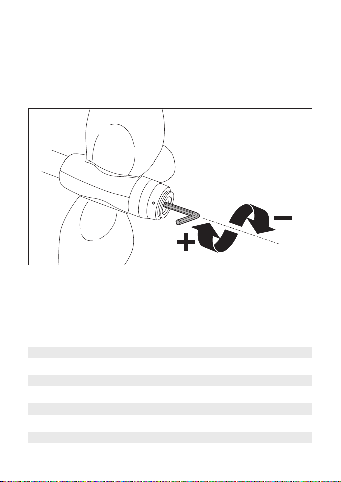
- its pitch can be regulated with simple actions without
dismantling the propeller;
- it avoids the accidental loss of the propeller thanks to simple
and effective solutions;
- the normal servicing just consists of applying some grease
through the nipple provided;
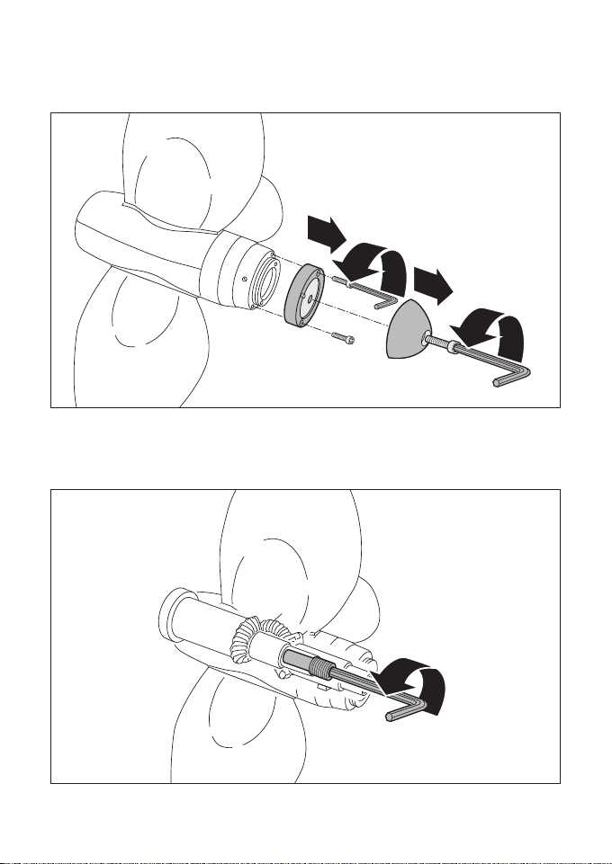
- the servicing of the propeller shaft has been made extremely
easy: the "JPROP" propeller can be dismantled without extractor
by exploiting the features of the fixing nut.
• Our technician choose the "JPROP" propeller suitable for your
boat on the basis of the data communicated through your
order.
J PROP
Variable pitch propeller
s.r.l.

IINDEX
Section 1 - Taper check Page 2
2 - Key check 3
3 - Threading’s length of the shaft 5
4 - Tightening the lock nut 6
5 - Installing the propeller on the shaft 7
6 - Removing the propeller from shaft 11
7 - Pitch adjustment 14
8 - Maintenance 20
9 - Spare parts 22
Note 30
Table 1 - Threading’s length of the shaft Page 5
2 - Lock nut - min. and max. N. of turns 6
3 - Allen keys to be used 13
Tables of the propeller pitch Page 16
Warning
During propeller assembly and maintenance operations follow the
rules of safety carefully, and in particular:
1 - make sure that the engine is OFF and that it cannot be
started accidentally,
2 - when handling the propeller do not put your hands on the
hub on the points where the blades rotate.

Section 1 - TAPER CHECK
It is very important to check that the propeller taper perfectly
matches the taper of the boat's shaft. You can easily check this
by removing the key before installing the propeller.
JP003
2
1
JP005
NO!
JP004
OK!
2

Section 2 - KEY CHECK
This check avoid serious damage to the propeller.
Make sure that the key:
1 - is at least 8 mm (5/16") away from the aft side of cone;
2 - does not touch the upper or the aft side of keyway
of the propeller ;
3 - does not have too much clearance in the keyway of the
shaft or sideways in the keyway of the propeller.
JP009
OK!
JP007
NO!
NO! NO!
NO!
JP008
NO! NO!
min. 8 mm
3

1 - Screw on the main nut (see point 5.6)
2 - mark the front limit of the propeller on the shaft.
After final installation the propeller must reach the same mark.
JP003
2
1
JP037
4
Put the propeller on the shaft without the key.

TABLE 1
The size of the thread of the shaft must be within the values listed
below:
Section 3 - THREADING’S LENGTH OF THE SHAFT
While tightening the retaining nut make sure that:
1 - it doesn’t meet with a strong resistance
2 - the threading of the shaft doesn’t bottom out in retaining nut
3 - the cones of the shaft and of the propeller match perfectly
JP011
OK!
JP011/1
NO!
NO!
hub dia
mm
63
83
93
116
min. th. lenght
mm (")
18 (3/4)
20 (1)
25 (1)
35 (13/8)
max. th. lenght
mm (")
25 (1)
27 (11/16)
35 (13/8)
45 (x/x)
max. dia thread
mm
20,00
24,00
31,75
40,00
Allen key type "A"
(see tab. 3)
5

JP012
hub dia
mm
63
83
93
116
thread
dia - pitch
16 x 1,5
16 x 1,5
18 x 1,5
24 x 2,0
minimum
N. of turns
6
6
7
7
maximum
N. of turns
15
15
18
18
Allen key type "B"
(see table. 3)
6
Table 2
The next table lists the min. and max. number of turns
depending on the threading.
Section 4 - TIGHTENING THE LOCK NUT
For a good working of the lock nut system it is necessary to take
some precautions. While tightening the lock nut make sure that
it turns:
1 - not less than the minimum figure listed in the table
2 - not more than the maximum figure listed in the table

Section 5 - INSTALLING THE PROPELLER ON THE SHAFT
To install the propeller on the shaft proceed as follows:
JP013
2
1
3
4
1 - remove the zinc anode with the Allen key type "B" and the
bronze ring with the Allen key type "C"
(see table 3 of section 6).
JP014
2 - insert the Allen key type «B» in the lock nut and turn it
counter-clockwise until it’s completely free. 7

JP015
2
1
controdado
3 - pull down the Allen key and pull out the lock nut.
4 - check the cone, the key and the thread as suggested in
section 1 - 2 -3
JP003/1
5 - insert the key on the shaft
8
lock nut

JP006
6 - put the propeller on a shaft.
(We advise to use locktite on a thread)
JP017
1
2
7 - tighten the retaining nut with the Allen key type "C" and with
the help of a metal tube 30/40 cm (12/16") long.
8 - check that the propeller reaches the same position on the
shaft as marked before (see section 1).
JP038
9

JP018
1
2
controdado
9 - tighten the lock nut with Allen key type "B" checking the
values listed in table 2.
10 - adjust, if necessary, the pitch of the propeller.
(see section 7)
JP019
1
2
4
3
11 - install on the propeller the bronze ring (Allen key type "C")
and the zinc anode (Allen key type "B").
Fixing the anode on the propeller is the last step of the
installation. The anode is necessary to protect the propeller from
damage due to electrolytic corrosion. A regular check and
replacement of the anode helps to maintain the propeller in the
best possible shape.
10
lock nut

Section 6 - REMOVING THE PROPELLER FROM SHAFT
Proceed as follow in order to remove the propeller from the
shaft:
JP031
2
1
3
4
1 - remove the anode (Allen key type "B", table 3) and the
bronze ring (Allen key type "C").
JP021
2 - insert the Allen key type "B" in the lock nut and turn it
counter-clockwise until it’s completely free. 11

JP022
controdado
2
1
3 - pull down the Allen key and pull out the lock nut.
JP023
2
1
4 - insert the Allen key type A in the retaining nut and turn it
counter-clockwise with the help of a metal tube 30/40 cm
(12/16") long.
After the first movement you'll feel an increased opposition due
to the extractor job of the nut.
Keep on unscrewing it till the propeller is detached from the
cone of the shaft.
12
lock nut

JP024
5 - when the retaining nut is loose remove the propeller
from the shaft
Table 3
Allen keys to be used when installing or removing a propeller:
hub dia
mm
63
83
93
116
key "A"
mm
12
12
14
19
key "B"
mm
6
6
8
10
key "C"
mm
3
3
4
4
key "D"
mm
3
3
3
3
13

JP031
2
1
3
4
JP033
1
2
3
JP026
0
0
L
R
JP025
0
0
0
L
R
1 - pull the cone of the propeller backward (the 4 projecting balls help
the holding of the hand) If the ogival nose doesn't move enough to
be free to turn follow the next steps. If it moves go to step 4.
2 - remove the zinc anode and the bronze ring (Allen keys "B" and "C",
see Section 6, table 3)
3 - remove the bronze "pitch lock" flange .
4 - put the propeller's blade in
feathering position.
5 - pull the ogival nose.
JP025/1
14
Section 7 - PITCH ADJUSTMENT
It’s possible to adjust the pitch anytime following these
procedure:

27
0
L
R
L
R
JP028
0
0
L
P
032
1
2
4
3
JP034
2
1
3
6 - turn the ogival nose towards the "R" or "L" side depending on the type
of the engine (rightway or leftway) and reach the notch of the
desired pitch.
7 - release the ogival nose.
8 - make sure that the reference line "0" matches the desired notch.
9 - make sure that the ogival nose backs itself firmly against the
props body.
10 - If you are sure that you reached the right pitch, reinstall the bronze
"pitch lock" flange in order to lock the ogival nose, but if you plan to
modify it again while the boat is in the water, do not install it now.
11 - put on the bronze ring and the zinc anode.
15
Attention : when the boat is out of the water the movement of the ogival
nose is easy. When the boat is in the water it takes more time to pull the
ogival nose as water has to fill the void created by the action. Drains are
built into the ogival nose to allow flooding of the void.

Hub dia 63 mm
pitch (inches p. r.)
Propeller dia
Notch
N. 13” 14” 15” 16” 17” 18”
1 1,863 2,007 2,150 2,293 2,437 2,580
2 3,735 4,022 4,309 4,597 4,884 5,171
3 5,622 6,054 6,487 6,919 7,352 7,784
4 7,533 8,112 8,692 9,271 9,851 10,430
5 9,476 10,205 10,934 11,663 12,392 13,121
6 11,462 12,343 13,225 14,107 14,988 15,870
7 13,498 14,537 15,575 16,613 17,652 18,690
8 15,597 16,797 17,997 19,197 20,397 21,596
9 17,771 19,138 20,505 21,872 23,239 24,606
10 20,032 21,573 23,114 *24,655 26,196 27,737
11 22,397 24,120 25,843 27,566 29,289 31,012
12 24,884 26,798 28,712 30,626 32,541 34,455
13 27,512 29,626 31,745 33,862 35,978 38,095
14 30,308 32,640 34,971 37,302 39,634 41,965
15 33,300 35,861 38,423 40,984 43,546 46,107
16 36,522 39,332 42,141 44,951 47,760 50,570
16
Calculation of the slip:
The following tables give the theoretical value of the pitch.
To obtain the real value multiply the datum being examined by a
reduction factor of 0.55.
E.g.: propeller body 63, Ø 16", adjusted to the 10th step.
Theoretical pitch *24.655"/rot.
Real pitch: 24.655 x 0.55 = 13.560 "/rot.

Hub dia 83 mm
pitch (inches p. r.)
Propeller dia
Notch
N. 16” 17” 18” 19” 20” 21” 22”
1 2,060 2,189 2,318 2,447 2,576 2,704 2,833
2 4,128 4,386 4,644 4,902 5,160 5,418 5,676
3 6,210 6,598 6,986 7,374 7,762 8,151 8,539
4 8,313 8,832 9,352 9,872 10,391 10,911 11,430
5 10,444 11,097 12,403 11,663 13,056 13,709 14,361
6 12,613 13,401 14,198 14,978 15,766 16,554 17343
7 14,826 15,753 16,679 17,606 18,533 19,459 20,386
8 17,094 18,162 19,231 20,299 21,376 22,436 23,504
9 19,425 20,640 21,854 23,068 24,282 25,496 26,710
10 21,832 23,197 24,561 25,926 27,290 28,655 30,019
11 24,326 25,847 27,367 28,888 30,408 31,928 33,449
12 26,921 28,604 30,287 31,969 33,652 35,334 37,017
13 29,633 31,485 33,337 35,189 37,041 38,893 40,745
14 32,479 34,509 36,539 38,569 40,599 42,629 44,659
15 35,480 37,697 39,915 42,132 44,350 46,567 48,785
16 38,659 41,076 43,942 45,908 48,324 50,741 53,157
17
Calculation of the slip:
The following tables give the theoretical value of the pitch.
To obtain the real value multiply the datum being examined by
a reduction factor of 0.55.
E.g.: propeller body 83, Ø 19", adjusted to the 10th step.
Theoretical pitch *25.926 "/rot.
Real pitch: 25.926 x 0.55 = 14.259 "/rot.

Hub dia 93 mm
pitch (inches p. r.)
Propeller dia
Notch
N. 21” 22” 23” 24” 25” 26” 27”
1 2,366 2,479 2,591 2,704 2,817 2,929 3,042
2 4,738 4,964 5,190 5,415 5,641 5,867 6,092
3 7,123 7,462 7,802 8,141 8,480 8,819 9,159
4 9,527 9,980 10,434 10,888 11,341 11,795 12,249
5 11,955 12,524 13,094 13,663 14,232 14,801 15,371
6 14,415 15,102 15,788 16,474 17,161 17,847 18,534
7 16,914 17,720 18,525 19,330 20,136 20,914 21,747
8 19,459 20,386 21,313 22,239 23,166 24,093 25,019
9 22,059 23,110 24,160 25,211 26,261 27,312 28,362
10 24,722 25,900 27,077 28,254 29,413 30,609 31,786
11 27,458 28,765 30,073 31,380 32,688 33,996 35,303
12 30,276 31,718 33,160 34,602 36,043 37,485 38,927
13 33,189 34,770 36,350 37,930 39,511 41,091 42,672
14 36,209 37,933 39,657 41,383 43,106 44,830 46,555
15 39,350 41,224 43,098 44,972 46,845 48,719 50,593
16 42,629 44,659 46,689 48,719 50,748 52,778 54,80
18
Calculation of the slip:
The following tables give the theoretical value of the pitch.
To obtain the real value multiply the datum being examined by
a reduction factor of 0.55.
E.g.: propeller body 93, Ø 24", adjusted to the 10th step.
Theoretical pitch *28.254 "/rot.
Real pitch: 28.254 x 0.55 = 15.539 "/rot.
Table of contents
Popular Marine Equipment manuals by other brands

urmet domus
urmet domus 1033/426 quick start guide

Simpson Lawrence
Simpson Lawrence Pacific C1250 Installation, operation & maintenance instructions

Whisper Tech
Whisper Tech WhisperGen 3000 Series Installation and commissioning manual

Teledyne
Teledyne Everywhereyoulook WAYFINDER manual

Furuno
Furuno NX-300 Operator's manual

DIGITAL YACHT
DIGITAL YACHT AISnet Internet Base Station Installation & quick start guide

Raymarine
Raymarine autopilot ST4000+ Owner's handbook

Trailer Valet
Trailer Valet 5X operating manual

Outback Power Systems
Outback Power Systems FX 2012MT Specification sheet

Boss marine
Boss marine MR1620S user manual

Sonic
Sonic KSE-310 instruction manual

Bennett Marine
Bennett Marine Lenco-to-BOLT instructions