PP5105/2022/Issue 1
Page 2 of 4
Status LED
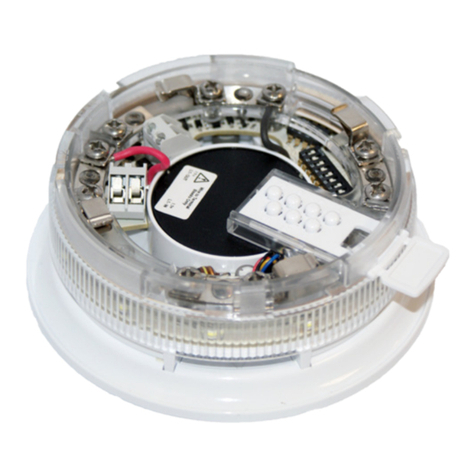
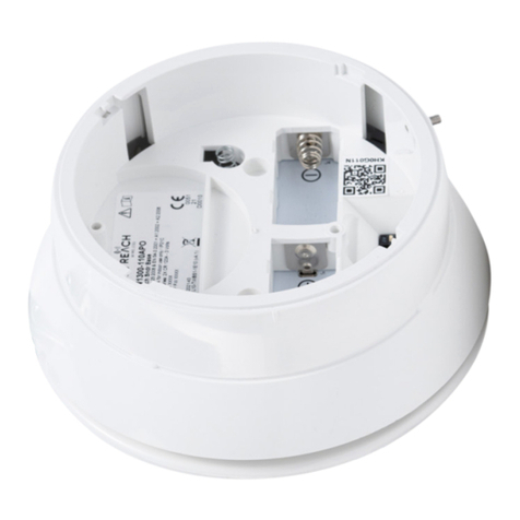
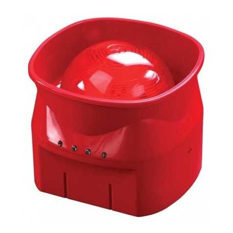
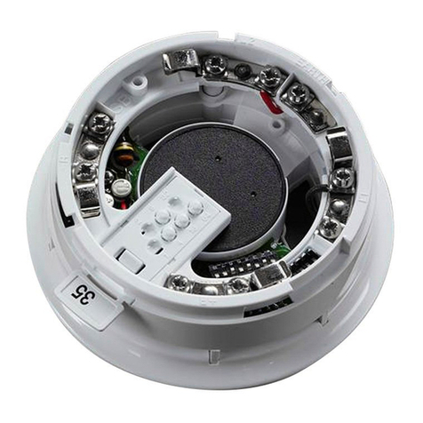
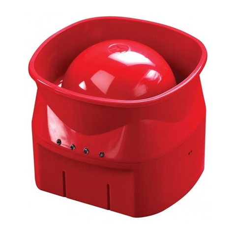
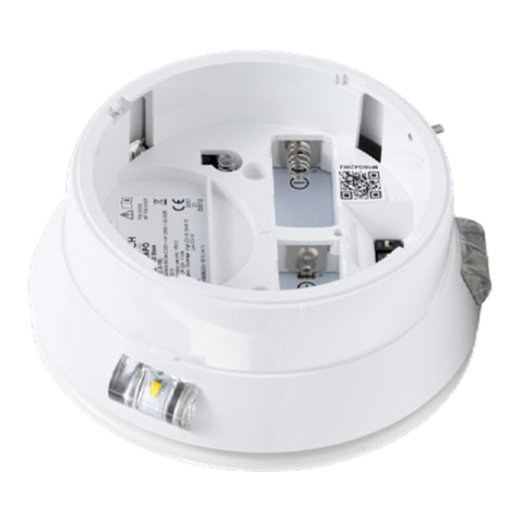
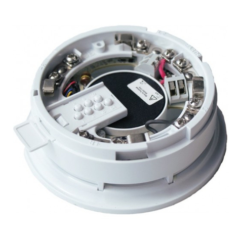
The REACH Wireless Open-Area Wall Sounder VAD Base
includes a 360° LED indicator which to indicate status
conditions. See table 1.
Table 1: REACH Wireless Device Status & LED
Indication
Device Status
LED Indication
Tamper Not
Activated
Tamper
Activated
Power Up Blinks green four times
Power Up (dip-switch ON) Blinks red four times
Entering Wake-Up Blinks alternatively green/red four
times
Link Success Blinks green four times, then
repeats
Link Failure
Enters wake-up mode and signals
‘Entering wake-up mode’ following
this failure
Normal Condition LED o LED o
Activation LED o Red on
Battery Faults LED o Amber blinking
every 5s
Tamper Fault LED o
Replaced Blinks amber two times
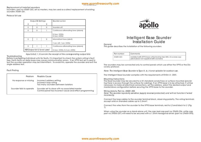
Tone & Volume Selection DIP Switch Settings
Device Addressing
Device addressing is handled by the REACH Wireless Loop-
Interface device (RW1700-030APO).
Devices are soft-addressed automatically when pairing with
the Loop Interface and can be changed manually. Hard-
addressing using Apollo XPERT cards are not supported.
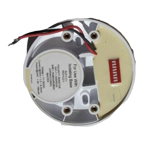
Table 2: REACH Wireless DIP Switch Functionality
DIP Switch
Number DIP Switch Group Function Notes
1
Tone Selection Check Tone Table
(Table 4)
2
3
4
5
6Volume Selection Check Volume
Table (Table 3)
7
8 High/Low Power LED Output N/A
Table 3: REACH Wireless Volume Table
Volume DIP Configuration
High* 11
Medium High 01
Medium Low 10
Low 00
*EN54-3 certified, for Tone Table (Table 4), see appendix
Communication
REACH Wireless Devices use ‘radio-frequency’ wireless com-
munication to connect to the Loop-Interface.
The Loop-Interface (RW1700-030APO) translates the wire-
less communication into wired Apollo protocol communica-
tion, with each device addressable individually by the fire
panel. See datasheets for the Loop-Interface for more infor-
mation.
Maintenance and Service
Maintenance must be performed in accordance with all
applicable standards. Clean the detector externally using a
soft damp cloth. For full cleaning and recalibration detectors
should be returned to Apollo Fire Detectors.
Batteries
REACH Wireless devices are supplied with two CR123 bat-
teries, battery A and B. The device switches periodically
between the two batteries on a controlled sequence. For cor-
rect operation of the device, both batteries are required with
adequate capacity reserves.
When battery A reaches a low power threshold, it will trig-
ger a fault. This fault requires both batteries to be replaced
in every instance as both batteries should be discharging
equally.
When one (or both) batteries lack power, the Loop-Interface
receives a low battery message and will signal this event on
its in-built display, as well as relay the low battery message
to the fire control panel. The battery fault will also be sig-
nalled by the device itself through its LED indicators if pro-
grammed (see table 1).
Tamper detection
REACH Wireless devices contain an anti-tamper mechanism.
In the event of removal from its base, it sends a tamper de-
tection message to the Loop-Interface.
Tampering detection is not signalled visually by the device
LED.
EMC Directive 2014/30/EU
REACH Wireless Open-Area Wall Sounder complies with the
essential requirements of the EMC Directive 2014/30/EU,
provided that it is used as described in this datasheet.
A copy of the Declaration of Conformity is available from
Apollo on request.
