FHF dEV20 User manual
ExII-Schallgeber / ExII-Sounder
dEV20
FHF BA 6947- 01 01/14
dEV20
1
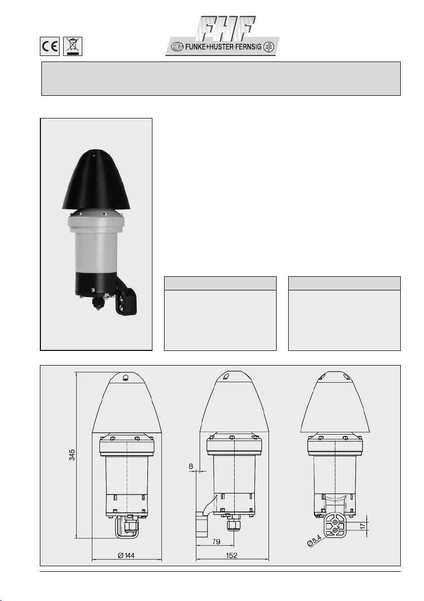
Anwendung
In explosionsgefährdeter Umgebung ist
es häufig erforderlich akustische Signale
zum Warnen, Melden und Signalisieren
einzusetzen. Der Schallgeber dEV20
liefert diese Möglichkeit. Er ist für Dauer-
betrieb ausgelegt. Der Schallgeber wird
durch Einschalten der Versorgungs -
spannung aktiviert. Der ExII-Schallgeber
dEV20 ist in der Schutzart IP66 ausge-
führt und kann in Räumen oder im
Freien installiert werden.
Aufbau
Der ExII-Schallgeber besteht aus einem
druckfesten Gehäuse aus Aluminium-
legierung und einer Schallführung aus
schlagfestem Kunststoff. Der Anschluss-
raum ist in der Zündschutzart „erhöhte
Sicherheit“ ausgeführt.
Ma zeichnung /
Dimensions
Das Gerät erfüllt die Anforderungen
der neuen EMV-Richtlinie 2004/108/EG
und der Niederspannungs-Richtlinie
2006/95/EG.
Die Konformität mit den oben
genannten Richtlinien wird durch das
CE-Zeichen bestätigt.
EMV-Richtlinie
Application
Hazardous areas often require the use
of acoustical signals for warning or
information purposes. The ExII-sounder
dEV20 offers both of these signalling
features. The device is designed for
continuous operation. If the supply
voltage is turned on, the sounder is
acti vated.
The ExII-sounder dEV20 is made to
protection category IP66 and may be
used indoors or outdoors.
Construction
The ExII-Sounder consists of a com-
pression-proof housing with aluminium
alloy and a sound channel of impact-
resistant polyester. The terminal com-
partment is executed in the protection
type „extended safety“.
The device complies with the require-
ments of the new EMC-directive
2004/108/EC and the low voltage
directive 2006/95/EC.
The conformity with the above direc-
tives is confirmed by the CE sign.
EMC-Directive

2
Umgebungsbedingungen
Umgebungstemperatur
entsprechend der
Temperaturklasse T6 -50°C ≤ Ta ≤ +60°C
Akustische Daten
Lautstärke max. 115 dB(A) in 3 Stufen absenkbar
um jeweils 10 dB
Signaltöne 32 pro Signalstufe
Lieferzustand S0: Ton 24 / S1: Ton 4
Gehäuseschutzart IP66
Schutzklasse I
Warnhinweise Wartezeiten vor dem Öffnen:
10 Min. bei 230 VAC / 2 Min. bei 24 VDC
Elektrische Daten
Leistungsaufnahme max. 14 W
AC Ue = 85 VAC ... 264 VAC
DC Ue = 24 VDC ±20% 19,2 VDC ... 28,8 VDC
Anschlussklemme
Bemessungsquerschnitt bis 2,5 mm2
Mehrleiteranschluss max. 2 x 1 mm2
Anzugsdrehmoment
für Klemmschraube 0,4 Nm
Kennzeichnung auf dem Typenschild
FHF Funke + Huster Fernsig GmbH · D-45478 Mülheim an der Ruhr
PTB 12 ATEX 1014
II 2 G Ex d e IIB + H2 T6 Gb
II 2 D Ex tb IIIC T85°C Db
-50°C Ta +60°C
Ui = )………………
Art.-Nr.: )………… F-Nr.: )………… ) Angaben variabel
WARNUNG · NICHT UNTER SPANNUNG ÖFFNEN
GEFAHR DURCH ELEKTROSTATISCHE ENTLADUNGEN · NUR FEUCHT REINIGEN
NACH DEM ABSCHALTEN 10 MINUTEN WARTEN VOR DEM ÖFFNEN
Technische Daten
Inbetriebnahme
• Befestigen Sie das Gerät mit zwei
Schrauben (Ø 8 mm) an die Wand.
Zur Korrektur des Abstandes zwi-
schen dem Trichter und der Wand
benutzen Sie das lose mitgelieferte
Abstandsstück.
• Nehmen Sie den Gehäusedeckel ab.
Muss die Einstellung der Lautstärke
und/oder der Signaltöne geändert
werden, verfahren Sie gemäß
„Einstellen der Lautstärke und der
Signaltöne“
•Führen Sie das Anschlusskabel
durch die Kabel- und Leitungsein -
führung (KLE).
• Schließen Sie die Leitungen an die
Klemmen gemäß Anschlussbild (auf
den Seiten 4 + 5) an. Schrauben Sie
den Gehäusedeckel wieder auf.
• Ziehen Sie den Überschuss am Kabel
aus dem Anschlussraum durch die
KLE heraus und fixieren Sie die Leitung
mit der Überwurf mutter der KLE.
Einstellen der Lautstärke
und des Signaltones
Zum Einstellen der Lautstärke und der
Signaltöne muss das Oberteil des
Gehäuses abgeschraubt werden. Die
elektrische Steckverbindung zum
Unterteil kann getrennt werden. Im
Gehäuseoberteil werden an den 12
Schiebeschaltern die Einstellungen vor-
genommen. Der Schallgeber dEV20
hat zwei Signalstufen. Der Signalton für
die erste Signalstufe wird mit den
Schiebeschaltern 1-5 (S0) entsprechend
der Signal-Auswahltabelle eingestellt.
Der Signalton für die zweite Signalstufe
wird mit den Schiebeschaltern 6-10
(S1) eingestellt.
Die Lautstärke wird mit den Schiebe-
schaltern 11 und 12 eingestellt (siehe
Tabelle).
Die Umschaltung von der ersten auf
die zweite Signalstufe erfolgt bei Geräten
für Gleichspannung durch zusätzliches
Anlegen der positiven Betriebsspannung
an Klemme 3. Bei Geräten für Wech-
selspannung erfolgt die Umschaltung
durch zusätzliches Anlegen der Phase
(L1) der Betriebsspannung an Klemme 3.
Nach Abschluss der Einstellungen muss
die elektrische Verbindung zum Unter-
teil wieder hergestellt werden und das
Oberteil mit den zugehörigen Schrauben
auf das Unterteil geschraubt werden.
(VORSICHT! Zündspalt nicht be -
schädigen.)
ISO 9001
Die Angaben über Lieferumfang,
Anwendung, Einsatz und Betriebs-
bedingungen entsprechend zum Zeit-
punkt der Drucklegung vorhandenen
Kenntnissen. Änderungen vorbehalten.
Recycling
Die Komplett-Entsorgung des Gerätes
erfolgt über den Elektronikabfall. Bei
der Demontage des Gerätes sind die
Komponenten Kunststoff, Metalle und
Elektronik separat zu entsorgen. In
jedem Fall sind die Entsorgungsbedin-
gungen des jeweiligen Einsatzlandes zu
beachten.
Sicherheitshinweise
Lesen Sie bitte diese Betriebsan leitung
und beachten Sie die landesspezi -
fischen Installationsstandards sowie die
geltenden Sicherheitsbestimmungen
und Unfallverhütungsvorschriften. Ein-
griffe in das Gerät über die anschluss-
bedingten Handhabungen hinaus dürfen
aus Sicherheits- und Gewährleistungs-
gründen nur durch den Hersteller vor-
genommen werden. Umbauten oder
Veränderungen am Produkt sind nicht
gestattet. Er ist nur in unbeschädigtem
und einwandfreiem Zustand zu betrei-
ben. Der elektrische Anschluss im
Gehäuse darf nur durch Fachkräfte
erfolgen.
Achtung Ex-Bereich
Für die Einhaltung, der auf dem Typen-
schild des Gerätes angegebenen Tem-
peraturklasse ist die Um gebungs -
temperatur, der Anschlussquerschnitt,
sowie Eigenerwärmung des vollstän -
digen Betriebsmittels zu beachten.
Die Verantwortung hinsichtlich be -
stimmungsgemäßer Verwendung des
Schallgebers, unter Bezugnahme der,
in dieser Anleitung vorhandenen Rah-
menbedingungen, liegt allein beim
Betreiber.
Wartung und Pflege
Die Vorgaben der EN 60079-17 hin-
sichtlich der regelmäßigen Überprüfung
des Explosionsschutzes sind einzu -
halten. Das Betriebsmittel enthält keine
zu wartenden Teile.
EG-Baumusterprüfbescheinigungs-Nr. PTB 99 ATEX 3128 X
Betriebsumgebungstemperatur Ta: -50°C bis +60°C
Gewindedurchmesser
Ø
M20 x 1,5
Gehäuseschutzart IP66
Zündschutzart Ex e II
Zur Montage der KLE sind nur geeignete Werkzeuge zulässig!
Der Kabelanschluss ist nur für fest verlegte Leitungen geeignet!
Hinweise zu Kabel- und Leitungseinführungen
3
Ambient condition
Ambient temperature
according to
temperature class T6 -50°C ≤ Ta ≤ +60°C
Acoustic specification
Volume max. 115 dB(A) reducible in 3 levels
each by 10 dB
Signal tone 32 for each signal level
Delivery condition S0: Tone 24 / S1: Tone 4
Housing degree of protection IP66
Protection class I
Warning Holding time before opening:
10 Min. in case of 230 VAC /
2 Min. in case of 24 VDC
Electric specification
Power consumption max. 14 W
AC Ue = 85 VAC ... 264 VAC
DC Ue = 24 VDC ±20% 19,2 VDC ... 28,8 VDC
Connecting Terminal
Rated cross-section up to 2.5 mm2 (AWG 14)
Multi-conductor connection max. 2 x 1 mm2
Tightening torque
for clamp screw 0.4 Nm
Identification on the name plate
FHF Funke + Huster Fernsig GmbH · D-45478 Mülheim an der Ruhr
PTB 12 ATEX 1014
II 2 G Ex d e IIB + H2 T6 Gb
II 2 D Ex tb IIIC T85°C Db0,
-50°C Ta +60°C
Ui = )………………
Art. no: )………… F no.: )………… ) Information variable
WARNING · DO NOT OPEN WHEN ENERGIZED
HAZARD BY ELECTROSTATIC DISCHARGE · JUST DAMP CLEANING
AFTER DE-ENERGIZING, DELAY 10 MINUTES BEFORE OPENING
Technical Specifications
Start-up
• Fix the device at the wall with two
screws (Ø 8 mm).
• To correct the distance between the
horn and the wall use the supplied
spacer.
• Remove the housing cover. If the
setting of the volume and/or signal
tones do not meet your require-
ments, you have the following
options according to „Setting of
volume and signal tones“
• Enter the connecting cable through
the cable and wire gland (KLE).
• Connect the wires to the clamps
according to connection diagram
(on page 4 + 5). Tighten the housing
cover.
• Pull the cable excess of the terminal
compartment through the KLE and
fix the wire with the gland nut of the
KLE.
Setting of volume and signal tone
To set volume and signal tones the
cover of the housing has to be remo-
ved. The electrical plug connection to
the bottom section can be cut. In the
upper section the setting can be
carried out at the 12 slide switches.
The sounder dEV20 disposes of two
signal levels. The signal tone for the
first level is adjusted with the slide swit-
ches 1-5 (S0) according to the signal
choice list. The signal tone for the
second signal level is adjusted with the
slide switches 6-10 (S1).
The volume is set by the slide switches
11 and 12 (see table).
The shift from the first to the second
signal level in case of devices direct
tension is realized by additional appli-
cation of a positive operation voltage
on clamp 3. In case of alternating ten-
sion the shift is made by additional
application of the phase (L1) of the
operation voltage on clamp 3.
After the completion of the setting the
electrical connection to the bottom
section has to be re-established and
the upper section has to be fixed with
the respective screws on the bottom
section. (CAUTION! Don’t damage the
gap of the joint.)
ISO 9001
The information regarding scope of
delivery, application, operation and
operation conditions is current as
of publication date and subject to
change.
Recycling
The complete disposal of the device is
made together with e-waste. When
disassembling the device the compo-
nents polyester, metal and electronics
have to be disposed separately. In any
case please be aware of the disposal
conditions of the specific country.
Safety instructions
Please read this manual and observe
the country-specific assembly stan-
dards as well as the valid safety
instructions and accident prevention
regulations. Intervention at the device
beyond the connection handling is the
exclusive business of the manufacturer.
Reconstructions or changes of the
product are not allowed. The device
shall only be used in a safe and proper
condition. The electrical connection in
the housing shall only be made by
skilled personnel.
Attention ex-area
To comply with the temperature range
indicated on the name plate of the
device, the ambient temperature, ter-
minal cross-section as well as the self-
heating of the operating material has to
be observed.
The responsibility regarding the inten-
ded use of the sounder, with reference
to the existent general framework in
these instructions shall be exclusively
incumbent on the operating company.
Care and maintenance
The requirements of EN 60079-17
regarding the regular control of the
explosion protection must be applied.
The signalling light contains no service-
able parts.
EC type examination certificate PTB 99 ATEX 3128 X
Ambient temperature Ta: -50°C to +60°C
Thread diameter
Ø
M20 x 1,5
Housing degree of protection IP66
Type of protection Ex e II
Only appropriate tools permitted for the assembly of the KLE!
Cable connection only suitable for static installed wires!
Remarks regarding the cable and wire glands

Anschlussraum / Terminal room
Bedienelemente im „d“-Raum / Operating control in the„d“-room
4
Lautstärke – Messmethode / Volume – Measuring method

Montage-Set / Mounting Kit
5
Anschlussklemmen
im Anschlussraum
Externe Beschaltung
1. Signalstufe: Schalter S
offen
2. Signalstufe: Schalter S
geschlossen
Connecting clamps
in the terminal compartment
Extern circuitry
1. signal stage: switch S
open
2. signal stage: switch S
closed
Anschlussklemmen
im Anschlussraum
Externe Beschaltung
1. Signalstufe: Schalter S
offen
2. Signalstufe: Schalter S
geschlossen
Die ordnungsgemäße Erdung und Montage des
Gerätes ist nach EN 60728-11/ VDE 0855-1 zu
beachten.
Das Gerät darf nur auf ebenen, tragfähigen und
vibrations freien Flächen montiert werden.
Falls am Standort mit Schwingen zu rechnen ist, so
muss zusätzlich das abgebildete Montage-Kit ver-
wendet werden.
A due grounding and assembly of the device
according to EN 60728-11/ VDE 0855-1 has to be
observed.
The device shall only be installed on plain, stable and
vibration-free surfaces.
If vibrations may occur, additionally the pictured
assembling kit has to be used.
Connecting clamps
in the terminal compartment
Extern circuitry
1. signal stage: switch S
open
2. signal stage: switch S
closed
Umschaltung der Signalstufen / Switching of the signal levels
Schallgeber für Gleichspannung / Sounder for DC voltage
Schallgeber für Wechselspannung / Sounder for AC voltage
Art.-Nr. /Art no.
Montage-Set / Mounting Kit 21 591 099

Signal-Auswahltabelle / Signal choice table
6
7

Änderungen und Irrtum vorbehalten
Subject to alterations or errors
Benutzerinformation
FHF Funke+ Huster Fernsig GmbH
Gewerbeallee 15-19
D-45478 Mülheim an der Ruhr
Phone +49/ 208/82 68-0
Fax +49/208 / 82 68-286
http://www.fhf.de
e-mail: info@fhf.de
Bei diesem Betriebsmittel handelt es sich um ein explosionsgeschütztes
Gerät für den Betrieb in einem Bereich in dem gelegentlich damit zu
rechnen ist, dass im Normalbetrieb explosionsfähige Gasatmosphäre
auftritt – als ein Gerät der Gruppe II Kategorie 2 ist es in der Zone 1
verwendbar. Damit ist das Gerät auch für Gruppe II und Kategorie 3
Verwendungen geeignet und kann in der Zone 2 betrieben werden.
Dieses Gerät ist außerdem geeignet für den Betrieb in einem Bereich,
in dem gelegentlich im Normalbetrieb damit zu rechnen ist, dass ex-
plosionsfähige Staubatmosphäre auftritt. Als ein Gerät der Gruppe III und
Kategorie 2 D ist es innerhalb der Zone 21 und der Zone 22 verwendbar.
Nachstehende Warn- und Sicherheitshinweise sind besonders
zu beachten:
1. Der Anschluss und die Installation haben unter Beachtung der
angegebenen Zündschutzart gemäß den vorgschriebenen Errich-
tungsvorschriften von einem unterwiesenen Fachmann zu erfolgen.
2. Das Gerät darf nicht in Bereichen eingesetzt werden, in denen
stark ladungserzeugende Prozesse, maschinelle Reib- und Trenn-
prozesse, das Sprühen von Elektronen (z.B. im Umfeld von
elektrostatischen Lackiereinrichtungen) sowie pneumatisch
geförderter Staub auftreten.
3. Dieses Gerät ist in Schutzklasse I aufgebaut und darf nur an der
vorgeschriebenen Spannung angeschlossen und betrieben werden.
Die Polaritätsangaben sind zu beachten.
4. Im beschädigten Zustand darf das Gerät nicht betrieben werden.
5. Bei Betrieb des Gerätes in gewerblichen Einrichtungen sind die
Unfallverhütungsvorschriften des Verbandes der gewerblichen
Berufsgenossenschaften für elektrische Anlagen und Betriebs -
mittel zu beachten.
6. Das Gerät darf nur unter den angegebenen Umgebungsbedingungen
betrieben werden. Widrige Umgebungsbedingungen können zur
Beschädigung des Gerätes führen und damit zu einer eventuellen
Gefahr für das Leben des Benutzers.
Widrige Umgebungsbedingungen können sein:
• Nässe, Stäube (Schutzart beachten)
• brennbare Gase, Dämpfe, Lösungsmittel,
welche nicht durch die Zündschutzart abgedeckt sind.
• zu hohe Umgebungstemperaturen (>+60°C)
• zu niedrige Umgebungstemperaturen (<-50°C)
7. Instandsetzungen dürfen nur vom Hersteller selbst oder von einer
vom Hersteller beauftragten Person, bei Durchführung einer
erneuten Stückprüfung für das Gerät, durchgeführt werden.
8. Reinigunsarbeiten dürfen wegen der Gefahr elektrostatischer Auf-
ladung nur mit einem feuchten Tuch erfolgen.
9. Es dürfen nur die vom Hersteller vorgeschriebenen Kabel- und
Leitungseinführungen verwendet werden.
10. Bei Anschluss von Leitungen und Einstellarbeiten im Anschluss-
raum „Erhöhte Sicherheit“ müssen das Gerät und die Leitungen
spannungsfrei geschaltet sein.
11. Der für das Gerät angegebene Temperaturbereich darf während
des Betriebes weder unter- noch überschritten werden. Unzulässige
Strahlungsenergie und Konvektion in der Geräteumgebung verhindern.
12. Das Gerät ist so zu platzieren, dass eine mechanische Beschädi-
gung, z.B. durch herab fallende Teile oder seitliche Stöße verhin-
dert ist.
13. Sollte das Gerät im Anschlussraum einen internen Steckplatz zum
Programmieren besitzen, ist dessen Benutzung nur außerhalb
des explosionsgefährdeten Bereiches erlaubt.
14. Für das Anschließen übernimmt der Hersteller keine Haftung!
Bei Nichtbeachtung der vorgenannten Punkte ist der Explosionsschutz
des Gerätes nicht mehr gegeben, dann stellt das Gerät eine Gefahr für
das Leben des Betreibers dar und kann die Zündung einer explosions-
fähigen Atmosphäre verursachen.
User Information
This electrical equipment is an explosion-proof device designed for
use in areas in which an explosive gas atmosphere will probably
occur from time to time during normal operation – as a group II
category 2 device it is designed for use in Zone 1. Thus the device
is also suited for group II and category 3 applications and may be
operated in Zone 2.
This device is also suited for operation in areas in which an explo-
sive dust atmosphere will probably occur from time to time during
normal operation. As a group III and category 2 D device it may be
used within Zone 21 and Zone 22.
Please note the following warnings and security information:
1. The installation and adjustment of the device must be carried
out by qualified personnel in accordance with the prescribed
installation regulations taking the specified type of protection
into account.
2. The device should not be operated in areas in which strong
charges are generated, machines work by friction or cutting,
electrons are sprayed (e.g. in the vicinity of electrostatic paint
equipment), or pneumatically transported dust occurs.
3. This apparatus is a Protective Class I device and may only be
connected to and operated at the voltage it was designed for.
Please pay attention to the polarity information.
4. If the device is damaged, it may not be operated.
5. While operating the device in business or industry facilities,
the legally required precautions against accidents resulting
from the use of electrical systems and devices must be taken.
6. The device may be operated solely under the stated ambient
conditions. Unfavourable ambient conditions can lead to
damage of the device and thus present a potential danger for
the user.
Such unfavourable ambient conditions could include:
• moisture, dust (pay attention to the degree of protection)
• Flammable gases, vapours, solvents not covered by the type
of protection
• too high ambient temperatures (>+60°C)
• Too low ambient temperatures (<-50°C)
7. Repairs may be carried out by the manufacturer or by a
person appointed by the manufacturer followed by a renewed
product conformity inspection.
8. The device may only be cleaned using a damp cloth in order
to avoid electrostatic charging.
9. Only cable glands as prescribed by the manufacturer may be
used.
10. Make sure the device and the wiring are voltage-free upon
connecting the wires in the ‘increased safety’ terminal room.
11. During operation of the device the temperature must not
exceed nor fall below the prescribed range of temperatures.
Prevent unallowed radiation energy and convection in the
vicinity of the device.
12. The device should be positioned in such a way that mechani-
cal damage, e.g. due to falling parts or lateral impact is
prevented.
13. If the device has an internal plug-in position for programming
in the terminal compartment, its usage is permitted only outsi-
de the explosive area.
14. The manufacturer cannot be made liable for damages arising
from or pertaining to the connection!
Should these points not be observed, the explosion protection of
the device will no longer be given. The device will then represent a
danger to the life of the user and can cause the ignition of an
explosive atmosphere.
V O R S I C H T !
Emittierte Geräuschpegel können zu
einem permanenten Hörverlust führen.
C A U T I O N !
Emitting sound level can
cause a permanent hearing loss.
This manual suits for next models
1
Other FHF Marine Equipment manuals


Popular Marine Equipment manuals by other brands


Kannad Marine
Kannad Marine SafeLink EPIRB user manual

Conrad
Conrad Dragon Force 65 Safety instruction

Danelec Marine
Danelec Marine DM100 S-VDR G2 user guide

Boss Audio Systems
Boss Audio Systems MR1420W user manual

Seastar Solutions
Seastar Solutions HA5477 installation instructions

Simrad
Simrad EK80 Harbour Acceptance Test