ITIONS AFFECTING
OPERATION
WEIGHTDISTRIBUTION
Positioning of we~yht(passengers and
gear) inside the boat has the following
effects:
A
SIi~ft~ngwrryht
to
rear (stern)
@
Generally Incredses speed and englne
RPM
@
At extremes, can cause boat to por
-
poise
@
Causesbowtobounce ~nchoppy water
(1
Increases danger of thefollow~ng-wave
splash~ngInto boat when comlng off
plane
B.
Shift~ngweight to front (bow)
lmproves ease of planing off
e
Improves rough water ride
0
At extremes, can cause boat to veer
back and forth(bowsteer).
BOTTOM OF BOAT
To maintain maxlmumspeed the follow
-
ing cond~tionsof the boat bottom should
beobserved:
A. Clean, free of barnacles and marine
growth.
B. Free of distortion, nearly flat where ft
contacts the water.
C. Straight and smooth, fore andaft.
L
RECOMMENDATIONS
Any
leaded or unleaded (lead
-
free) gaso
-
line,that willsatisfactorily operateanauto
-
mobile engine is suitable for use in these
model outboard motors.
However, gasolines containing alcohol.
e~thermethyl alcohol (methanol)or ethyl
(ethanol)may cause increased:
s
Corrosion of metal parts.
c
Deteriorat~onof elastomer and plastic
parts.
s
Fuel permeation through flexible fuel
lines
Wear and damage of internal engine
parts.
Stiirting and
operating
diff~cult~es.
Some of these adverse effects are due to
thetendency of gasolinescontaining alco
-
holtoabsorb rnoisturefromthe air, result
-
ing in a phase of water and alcohol
separating from the gasoline in the fuel
tank.
The adverse affects of alcohol are more
severe with methyl alcohol (methanol)
and arc worsu w~thIncreasing alcohol
content.
A
WARNING
FIREANDEXPLOSIONHAZARD:Fuel
leakagefromanypartofthefuelsystem
canbeafireandexplosionhazardwhich
cancauseseriousbodilyinjuryordeath.
Carefulperiodicinspection oftheentire
fuel system is mandatory, particularly
after storage. All fuel components in
-
cluding fuel tanks, whether plastic,
metal or fiberglass, fuel lines, primer
bulbs, fittings, fuel filters and car
-
buretors should be inspected for leak
-
age, softening, hardening, swelling or
corrosion. Any sign of leakage or de
-
teriorationnecessitates replacementbe
-
fore further engine operation.
Because ofthe possible adverse effects
ofalcoholingasoline,
it
isrecommended
that only alcohol
-
free gasoline beused
where possible. If only alcohol-con-
tainingfuelisavailable, orifthepresence
of alcohol is unknown, then increased
inspection frequency for leaks and ab
-
normalities is required.
FUEL
RECOMMENDATIONS
(Continued)
A
wmN1w
USECAREwhentransportingfuelcon
-
tainer, whether in a boat or car. DO
NOT fill fuel container to maximum
capacity. Gasoline willexpandconsider
-
ably as
it
warms up and can build up
pressure inthe fuelcontainer. This can
cause fuel leakage and a potential fire
hazard.
OILRECOMMENDATIONS
A
CAUTION
The use of other than recommended
gasoline and Quicksilver 2
-
Cycle Out
-
boardOiloranacceptableBIATC
-
Woil
maycausepistonscoring, bearingfailure
or both. DO NOT, under any circum
-
stances. usemulti
-
gradeorotherhighly
detergent automobileoils or oils which
contain metallic additives.
Mix recommended gasoline w~thQuick
-
silver 2
-
CycleOutboardOilinratioshown
inthefollowingchart.Inanemergency, ~f
this is not available, substitute a high
quality 2
-
cycle
oil
that is Intended for
outboarduseandmeetsBIA ratingTC-W,
shownonoilcontainer.Usetheoilmanu
-
facturer's recommended gasol~ne-oilmix
-
ture as shown on the label (NOT TO
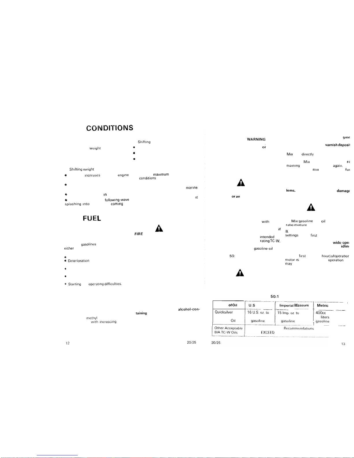
EXCEED 50:
1
RATIO).
MIXINGINSTRUCTIONS
A
WARNING
Observe fire prevention rules, particu
-
larly NOSMOKING. Mix fueloutdoors
or inwell ventilated location.
IMPORTANT: Always use fresh
yasc
line. Gasoline whichis keptintank to
longwillformgumand
varnishdeposil
whichmaycausetrouble.
MIX fuel d~rectlyinto remote tank. P
OL
small, equal amounts
of
gasoline ando
into tank. MIX thoroughly, then add re
ma~n~ngoilandgasoline.Mix agai~r.Kee
fuel clean and mlx each batch of fuf
exactly the same way.
IMPORTANT: Use recommende
amount of2
-
cycleoil. Toomuchorto
little oil can cause performance prot
lems. aswellasseriousenginedamagf
MOTOR BREAK
-
IN PROCEDURE
A
CAUTION
Follow break
-
inprocedurecarefully.
A
MIX gasohne and 011at normal 50
ratlo mlxture
B.
Operate new motor at varied throttl
sett~ngsfor the fwst hour (one hour).
IMPORTANT: Avoid both wide-ope1
throttle operation andprolonged idlin!
during first hour.
C
After f~rsthour(onehour)ofoperatlor
motor
IS
ready for normal
operation
an
may he runat any speed
A
CAUTION
DONOTEXCEED thefullthrottle RPN
range. See SPECIFICATIONS for RPN
range.
NORMAL
50:l
FUELMIXTURE
Type of Oil
/
U.I Measure
/
lmper~al
---
Measur.
1
Metr~cMeasure
-
Quicks~lver 16USozto 15lmpozto 400cc to each
2
-
Cycle each 6 gallons each
5
Imp gallons 20 l~tersof
Outboard
011
of gasol~~te of gasol~r~e aasol~ne
--
-
Use at Manufacturer's Recummenddtlons
DO NOT EXCtED
50
1

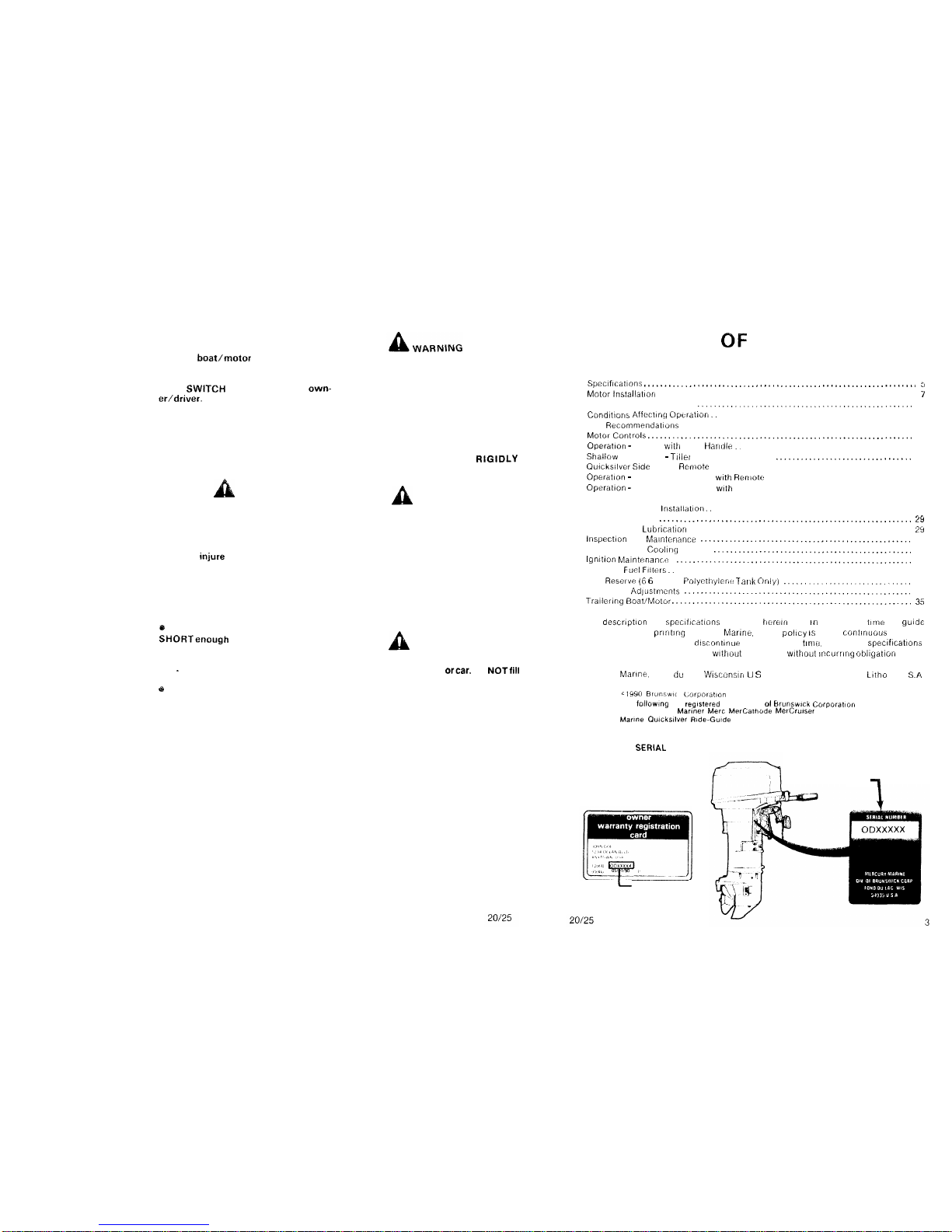
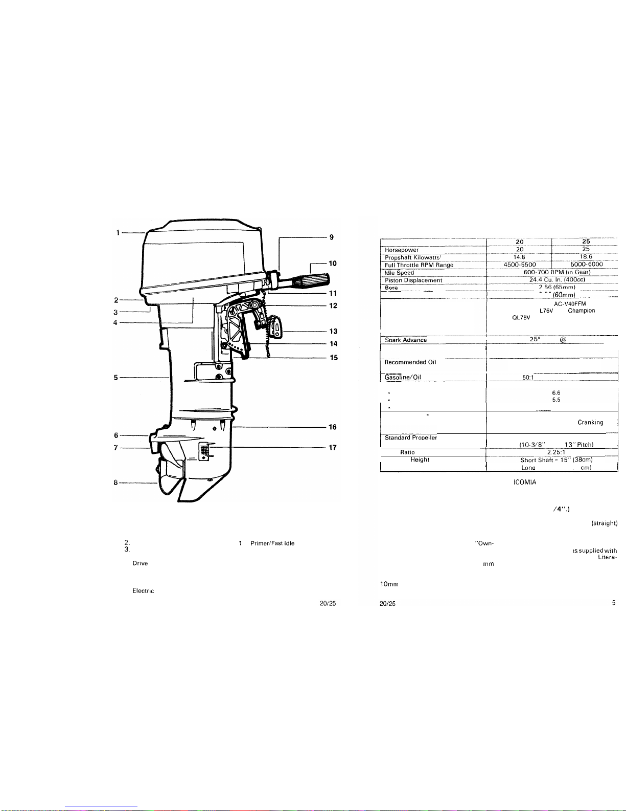

 User manual")


