Barrus X05 User manual

ORIGINAL INSTRUCTION
RDG603B2 –Issue 1
ELECTRIC OUTBOARD MOTOR
OPERATORS MANUAL
For the following models:
X05
X10
RDG603B2 –Issue 1 Page 2 of 88
SAFETY
Barrus is concerned for your safety. We use safety statements throughout the manual to call
your attention to the potential hazards associated with the operation of your electric
propulsion outboard.
Follow the precautions listed throughout the manual before operation, during operation and
during servicing/maintenance procedures for your safety, the safety of others and to protect
the performance of your motor.
Safety alert symbols appear throughout the manual. It means attention, be alert as your safety
is involved. Please read and follow the message that appears after the safety alert symbol.
NOTICE:
This indicates a situation which can cause damage to the
machine, personal property and/or the environment or cause the
equipment to operate improperly
CAUTION:
This indicates a hazardous situation which, if not avoided, could
result in minor or moderate injury.
WARNING:
This indicates a hazardous situation which, if not avoided, could
result in death or serious injury.
DANGER:
This indicates a hazardous situation which, if not avoided, will
result in death or serious injury.

RDG603B2 –Issue 1 Page 3 of 88
Engine Details
Engine Model Number:
Engine Serial Number:
Please enter your engine model number and serial number in the space provided above.
Please quote the engine identification number during any enquiry or when ordering spare
parts. Information about the engine serial number and its location on the engine can be found
in SECTION 2 of the manual.
This manual is for the following models:
•EZ-X05T
•EZ-X05R
•EZ-X10T
•EZ-X10R
Note: T = Tiller Steer, R = Remote Steer
Description
This range of electric outboards are unique in their design. Using a permanent magnet three
phase D.C. brushless, water-cooled 48v electric motor, which is mounted directly behind the
propeller. This gives an efficient and trouble-free method of power delivery. There is no
traditional type impeller to wear out or change. Salt, silt, and sand does not enter the motor
and, because there is no coolant or water inside the outboard, there is no danger of frost
damage in the winter. This results in your electric outboard requiring far less maintenance
than a conventional petrol unit.
They can be tiller or use an inboard shift and steering system. Bluetooth performance
monitoring system is used to indicate main parameters.

RDG603B2 –Issue 1 Page 4 of 88
Outboard specifications, Benefits and Optional extras
Specifications:
•48 Volt electric outboard
•CE Marked
•UKCA Marked
•Water cooled permanent magnet, brushless electric motor
•Variable speed
•Adjustable leg length from short to long shaft
•Outboard tilt lock
•Adjustable transom angle position
•Safety lanyard
Benefits:
•Variable speed ranges. Can be locked for commercial and hire boat situations
•No canal, river or sea water enters the system
•No coolant to change
•No problems in shallow or dirty water
•No water pump impeller to replace
•Direct drive –no shaft gears or oil changes required
•Motor overload cut out
•Spare props of different sizes readily available
•Spare parts readily available
•Near silent in operation
Optional extras:
•Lithium-Ion Polymer batteries available
•Multiple battery packs can be linked
•Remote shift throttle lever for inboard steering position
•Cable steering system for inboard steering wheel application
•Other optional extras not listed are available

RDG603B2 –Issue 1 Page 5 of 88
Operators Manual
NOTICE:
THIS MANUAL FORMS AN INTEGRAL PART OF THE OUTBOARD IT ACCOMPANIES,
IF A TRANSFER OF TITLE OCCURS, IT MUST ALWAYS BE HANDED OVER TO THE
NEW OWNER.
Thank you for purchasing this electric outboard motor from Barrus. This manual has been
compiled to help you to operate your outboard and its associated parts with safety and
pleasure. Please read it and familiarise yourself with the outboard and its parts before
operation.
The information and recommendations given in this manual are based on the latest
information available at the time of publication. Barrus reserve the right to change the
specification of its products and manuals without prior notice.
Depending upon the equipment specification of the outboard and accessories fitted, there
may be discrepancies or differences with the information presented in this handbook. No
claims may be pursued in this respect.
Ensure that you read and understand the contents of the manual before attempting tooperate
the unit.
Disclaimer: All product, product specifications and data are subject to change without notice
to improve reliability, function or design or otherwise. All product information is correct at the
time of issue.

RDG603B2 –Issue 1 Page 6 of 88
WARRANTY
This Limited Warranty provides coverage for one (1) year for all commercial applications and
two (2) years for leisure customers. This is for mechanical parts and electrical parts from the
date of warranty registration. The warranty is for non-serviceable items. The repair or
replacement of parts, or the performance of service under this warranty, does not extend the
life of this warranty beyond its original expiry date.
To ensure that you have been registered for your warranty, please detach and fill in the form
on the back of this manual. Return it to the address given or email to
The Warranty will only apply if the following have been carried out and the registration form
has been completed and returned to Barrus.
CONDITIONS THAT MUST BE MET IN ORDER TO OBTAIN WARRANTY COVERAGE
Warranty coverage is only available from Barrus or an authorised dealer in the country in
which the sale occurred. Routine maintenance outlined in the Owner’s Manual must be
performed using genuine parts in order to maintain warranty coverage. If the customer does
not carry out normal maintenance or makes unauthorised alterations or modifications the
warranty coverage will become void, Barrus reserves the right to make future warranty
coverage possible only with proof of proper maintenance.
WARRANTY CLAIMS
Warranty claims shall be made directly to Barrus or by an authorised dealer.
The dealer will then arrange for the inspection and any necessary repairs. If the repairs
carried out are not covered by the warranty, the purchaser shall pay for all related labour and
material, and any other expenses associated with that service.
WHAT IS NOT COVERED
This limited warranty does not cover routine maintenance items, adjustments, normal wear
and tear, damage caused by abnormal use (such as operating in shallow water), operation
of the product in a manner inconsistent with the recommended operation/ duty cycle section
of the Owner’s Manual, accident, submersion, improper installation (proper installation
specification and techniques are set forth in the Operations and First time running sections
in this manual), use of an accessory or part not manufactured or sold by us, or alteration or
removal of parts. Expenses related to crane-out, launch, towing, storage, telephone, rental,
inconvenience, slip fees, insurance coverage, loan payments, loss of time, loss of income, or
any other types of accidental or consequential damages are not covered by this warranty.

RDG603B2 –Issue 1 Page 7 of 88
Damage due to rust or corrosion, submersion, or unreasonable exposure to the environment,
such as exposure to high humidity, rain fall, orseawater, or conditions resulting in the freezing
of cooling water are also not covered.

RDG603B2 –Issue 1 Page 8 of 88
Index Page
SECTION 1 –Safety Precautions......................................................................................11
1. General.........................................................................................................................11
2. Lifting ............................................................................................................................11
3. Rotating Parts ...............................................................................................................11
4. Propeller........................................................................................................................12
5. Electrics ........................................................................................................................12
6. Batteries........................................................................................................................12
7. Safety Lanyard..............................................................................................................13
8. Motor Overload .............................................................................................................14
9. Modifications.................................................................................................................14
10. Boat...............................................................................................................................14
11. Passenger Training.......................................................................................................14
12. Terminal Crimping.........................................................................................................15
13. Applicable Standards ....................................................................................................15
SECTION 2 –Component Identification...........................................................................16
1. Tiller Control Model........................................................................................................16
2. Tiller Control ..................................................................................................................16
3. Remote Control Model (Option).....................................................................................17
4. Speed and Direction Control Lever (Option)..................................................................17
SECTION 3 –Installation...................................................................................................18
1. Unpacking the Outboard Motor ....................................................................................18
2. Adjusting the Outboard Motor Transom Height ............................................................19
3. Mounting of the Outboard Motor...................................................................................20
4. Adjusting the Outboard Steering Lock...........................................................................22
5. Adjusting the Outboard Angle.......................................................................................22
6. Battery Selection...........................................................................................................23
7. Lithium Ion Polymer (LiFePO4) Batteries......................................................................23
8. Battery Features (EB-4830 / EB-4850) .........................................................................26
9. Lithium-Ion Polymer (LiFePO4) Batteries Precautions (EB-4830 / EB-4850)................29
10. Lithium-Ion Polymer (LiFePO4) Batteries Warnings (EB-4830 / EB-4850)....................29
11. Battery Re-Booting........................................................................................................29
12. Battery Type Selection..................................................................................................29

RDG603B2 –Issue 1 Page 9 of 88
13. Anderson Type Connectors..........................................................................................30
14. Battery Installation........................................................................................................30
15. Battery Storage ............................................................................................................31
16. Connecting Speed and Direction Control Lever (Option)..............................................31
SECTION 4 –Operation.....................................................................................................33
1. General.........................................................................................................................33
2. Starting Procedure (Outboard Motor with tiller control).................................................34
3. Starting Procedure (Outboard motor with speed and direction control lever)................35
4. Stopping Procedure (Outboard Motor with tiller control) ...............................................36
5. Stopping Procedure (Outboard motor with speed and direction control lever)..............36
6. Tilting the Electric Outboard..........................................................................................37
7. Application Downloads and Information........................................................................39
SECTION 5 –Maintenance................................................................................................42
1. General.........................................................................................................................42
2. Installing propeller (X05) ...............................................................................................43
3. Installing Propeller (X10)...............................................................................................44
4. Controller Alignment......................................................................................................47
SECTION 6 –Transportation and Storage.......................................................................48
1. Transporting..................................................................................................................48
2. Storage .........................................................................................................................48
SECTION 7 –Wiring Diagrams .........................................................................................49
1. Wiring Diagram for Electric Propulsion Outboard..........................................................49
SECTION 8 –Technical Data ............................................................................................50
1. Outboard Data...............................................................................................................50
2. Dry Weight of Outboard Data........................................................................................50
3. Shipping Weight and Packaging Dimensions................................................................50
4. Outboard Dimensions ...................................................................................................51
SECTION 9 –System Protection Characteristics ...........................................................53
SECTION 10 –Spare Parts................................................................................................54
SECTION 11 –Security Products.....................................................................................56
1. STAZO Nutlock.............................................................................................................56
2. STAZO Security Chain..................................................................................................56
3. STAZO Bracket Nut ......................................................................................................57

RDG603B2 –Issue 1 Page 10 of 88
4. STAZO Outboard Lock..................................................................................................57
5. Talamex Outboard Motor Lock......................................................................................58
SECTION 12 –Afterlife Recycling ....................................................................................59
SECTION 13 –Declarations ..............................................................................................60
1. Declaration of Conformity for Recreational Craft Propulsion Engine with the
requirements of Directive 2012/53/EU. .........................................................................60
2. Declaration of Conformity for Recreational Craft Propulsion Engine with the
requirements of the Recreational Craft Regulations 2017 (UKCA Marking)..................62
3. LiFEP04 Battery TUV Safety Data Sheet......................................................................64

RDG603B2 –Issue 1 Page 11 of 88
SECTION 1 –Safety Precautions
1. General
NOTICE:
NEVER PERMIT ANYONE TO OPERATE THE OUTBOARD WITHOUT PROPER
TRAINING.
Ensure that the engine battery isolator switch is in the off position before connecting the
battery or carrying out any maintenance/ repairs. Also, when the outboard is not in use.
2. Lifting
DANGER:
CRUSH HAZARD! NEVER STAND UNDER A HOISTED ENGINE. IF THE HOIST
MECHANISM FAILS, THE ENGINE WILL FALL ON YOU, CAUSING SERIOUS INJURY
OR DEATH.
•Note: Suitable safe lifting equipment must be used to lift,move and mount the outboard
onto the boat.
•The batteries used for the outboard will be heavy. Make sure safe lifting procedures
or suitable cranes or hoists are used when moving and installing them.
3. Rotating Parts
WARNING:
SEVERE HAZARD! KEEP HANDS AND OTHER BODY PARTS AWAY FROM
MOVING/ROTATING PARTS. WEAR TIGHT FITTING CLOTHING AND KEEP YOUR
HAIR SHORT OR TIE BACK. REMOVE ALL JEWELLERY BEFORE COMMENCING
WORK. CHECK BEFORE STARTING THE OUTBOARD THAT ANY TOOLS OR RAGS
USED DURING MAINTENANCE HAVE BEEN REMOVED FROM THE AREA.
RDG603B2 –Issue 1 Page 12 of 88
The outboard and its accessories are not intended to be put into operation until they are
integrated into the boat as a whole. The top cowl must always be fitted whilst the motor is
running.
4. Propeller
CAUTION
•The propeller has sharp edges which can cause injury even when it is stationary. If
there is someone in the water near the motor, it must be switched off.
•If the propeller is damaged, itmay become unbalanced and cause either bad vibrations
or the outboard to fail. Do not use the outboard in this situation.
5. Electrics
CAUTION
•Do not touch any electrical parts while operating the motor. The electrical parts may
cause shock or electrocution.
•Ensure all electrical connections are insulated against accidental short circuit.
6. Batteries
DANGER:
EXPLOSION HAZARD! NEVER SHORT OUT THE BATTERY TERMINALS,
INCLUDING WHEN CHECKING THE REMAINING BATTERY CHARGE THIS WILL
RESULT IN A SPARK AND MAY CAUSE AN EXPLOSION OR FIRE.
RDG603B2 –Issue 1 Page 13 of 88
WARNING:
BURN HAZARD! BATTERIES CONTAIN SULPHURIC ACID. NEVER ALLOW
BATTERY FLUID TO COME IN CONTACT WITH SKIN, EYES OR CLOTHING. SEVERE
BURNS COULD RESULT. MAKE SURE THE CORRECT PERSONAL PROTECTION
EQUIPMENT IS WORN.
•Batteries can produce explosive gases; keep sparks and flames away from the battery.
NO SMOKING
•Lead Acid batteries contain sulphuric acid; if splashed on skin or eyes, flush well with
water and seek medical advice.
•Keep battery tops and battery compartment ventilated at all times.
•If disconnecting the battery; remove the earth lead FIRST; and re-connect it last.
•If charging the battery; ensure that the charger is switched off before connecting and
disconnecting.
•Do not tip the battery on its side.
•Please see label on battery or manufacturer’s instructions for specific information.
•A battery master (on/off) switch must be installed in the system.
•Lithium ion batteries have other safety features that must be followed, refer to Section
3–Installation and Section 13 –Declarations for more information.
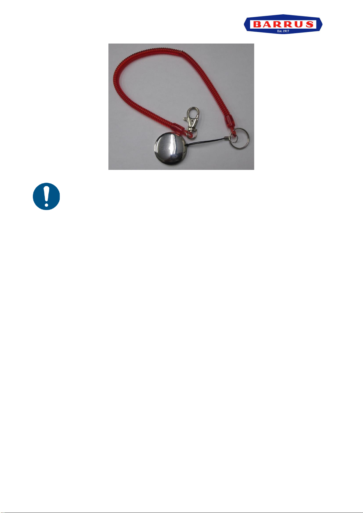
7. Safety Lanyard
WARNING:
•The magnetic safety lanyard tag should always be attached to the stop switch area
on the outboard tiller or remote shifter and the person operating the boat before the
motor is started. This will prevent the outboard from operating if the operator falls
overboard or leaves the helm.
RDG603B2 –Issue 1 Page 14 of 88
Figure 1: Safety Lanyard
The outboard will not operate if the safety lanyard is not in place. Ensure there
is a spare one on the boat and passengers know where it is.
8. Motor Overload
•If the motor is excessively overloaded (by either extended running at high speed or
using a propeller which is too big for the application) the motor will derate.
•If the motor stops all drive will be lost, which may be hazardous.
•If the motor stops, move the speed control lever to the stop position. Slowly move the
speed control to the drive position which will start the motor again.
•Continue at a reduced speed until the initial cause of the overload has been resolved.
9. Modifications
Do not attempt to modify the outboard motor as this is likely to reduce safety and reliability.
Any modifications will mean that the outboard will not be liable for warranty and maybe illegal
to use.
10. Boat
•Ensure the boat, that the outboard motor is being fitted to, has the capability of
accommodating the power and weight of the unit. (including the batteries).
•Ensure that any requirements of the boat manufacturer are adhered to.
•Consider location of the batteries in regard to weight distribution within the boat.
11. Passenger Training
•Ensure that at least one Passenger is trained to operate the boat in the event of an
emergency.

RDG603B2 –Issue 1 Page 15 of 88
12.Terminal Crimping
Ensure that a professional type crimping tool is used for crimping all heavy-duty cable
connections. Failure to do so can result in poor performance, system failure, terminal
overheating or in some cases melting of plastic terminal plugs or even fires.
13.Applicable Standards
Ensure that the fitting and installation of the electric outboard motor, batteries, battery
storage, cables and control systems comply with all relevant local, national and international
standards.

RDG603B2 –Issue 1 Page 16 of 88
SECTION 2 –Component Identification
1. Tiller Control Model
Figure 2: Tiller Controlled Outboard
2. Tiller Control
Figure 3: Tiller Control
Note: A number of optional extras may be fitted to the motors, that are not shown here.
Note: The serial number can be found on the top of the control unit.
Note: The On/Off Power Button is illuminated green when it is in the on position.
Description*
1
Outboard Cowl
2
Tiller Control
3
Transom Mounting Bracket
4
Leg
5
Anti-Cavitation Plate
6
Motor
7
Propeller
Description*
1
Speed Control Twist Grip
2
Direction Display
3
Safety Lanyard
4
Mode Switch
5
On/Off Power Button
6
Neutral Position Indicator
RDG603B2 –Issue 1 Page 17 of 88
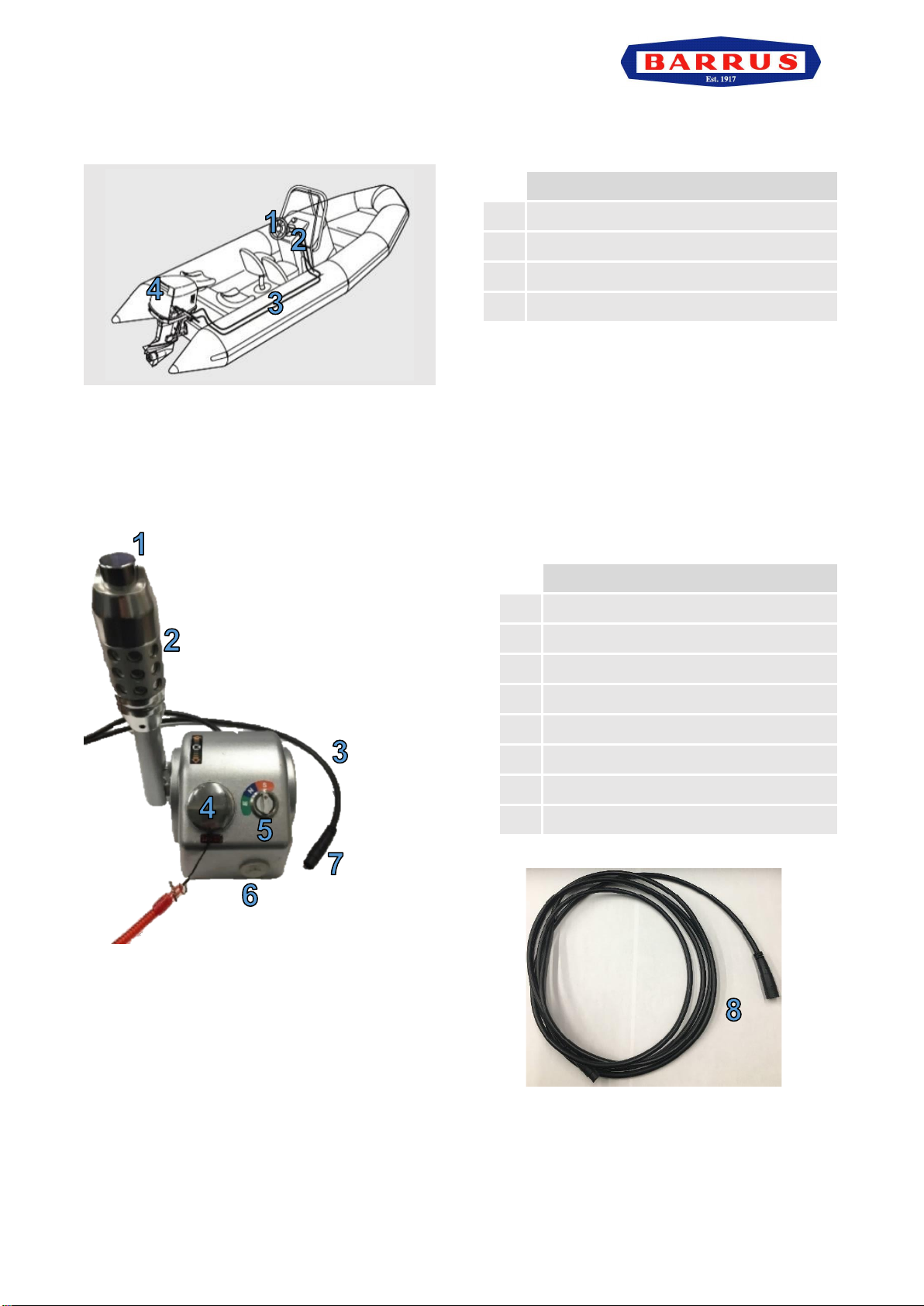
3. Remote Control Model (Option)
Figure 4: Remote Controlled Outboard
Note: A number of optional extras may be fitted to the outboards, that are not shown here.
4. Speed and Direction Control Lever (Option)
Figure 5: Speed and Direction Control Lever
Figure 6: Extension Cable
Description*
1
Steering Wheel
2
Speed and Direction Control Lever
3
Steering Cable
4
Electric Outboard
Description*
1
Safety Lock
2
Control Grip
3
Connecting Cable
4
Safety Lanyard
5
Mode Switch
6
On/Off Power Button
7
Extension Lead Connecting Plug
8
Extension Cable (3.1 Metres)

RDG603B2 –Issue 1 Page 18 of 88
SECTION 3 –Installation
NOTICE:
REFER TO THE BARRUS MANUAL PRIOR TO INSTALLING THE MOTOR.
1. Unpacking the Outboard Motor
•The outboard motor will arrive in a wooden box. Section 8.3 details shipping weight
and packaging dimensions. Use suitable personal protective equipment for unboxing.
Figure 7: How the outboard motor will arrive
•Use a screwdriver to open the wooden box carefully. Do not damage the wooden box.
•Make sure to remove all screws and/ or staples from the sides of the box.
Figure 8: Opening the wooden box
•Check to make sure the following parts are in the box:
1. Outboard Motor
2. Safety Key
3. Anderson Connector
4. Hexagonal Spanner and Screwdriver
5. Speed and Direction Control Lever (Option)
RDG603B2 –Issue 1 Page 19 of 88
Note: There is a right-handed speed and direction control lever available at an additional cost
(Part No.: GM-TRC-010R)
Note: Assembly instructions can be found in Section 5 - Maintenance.
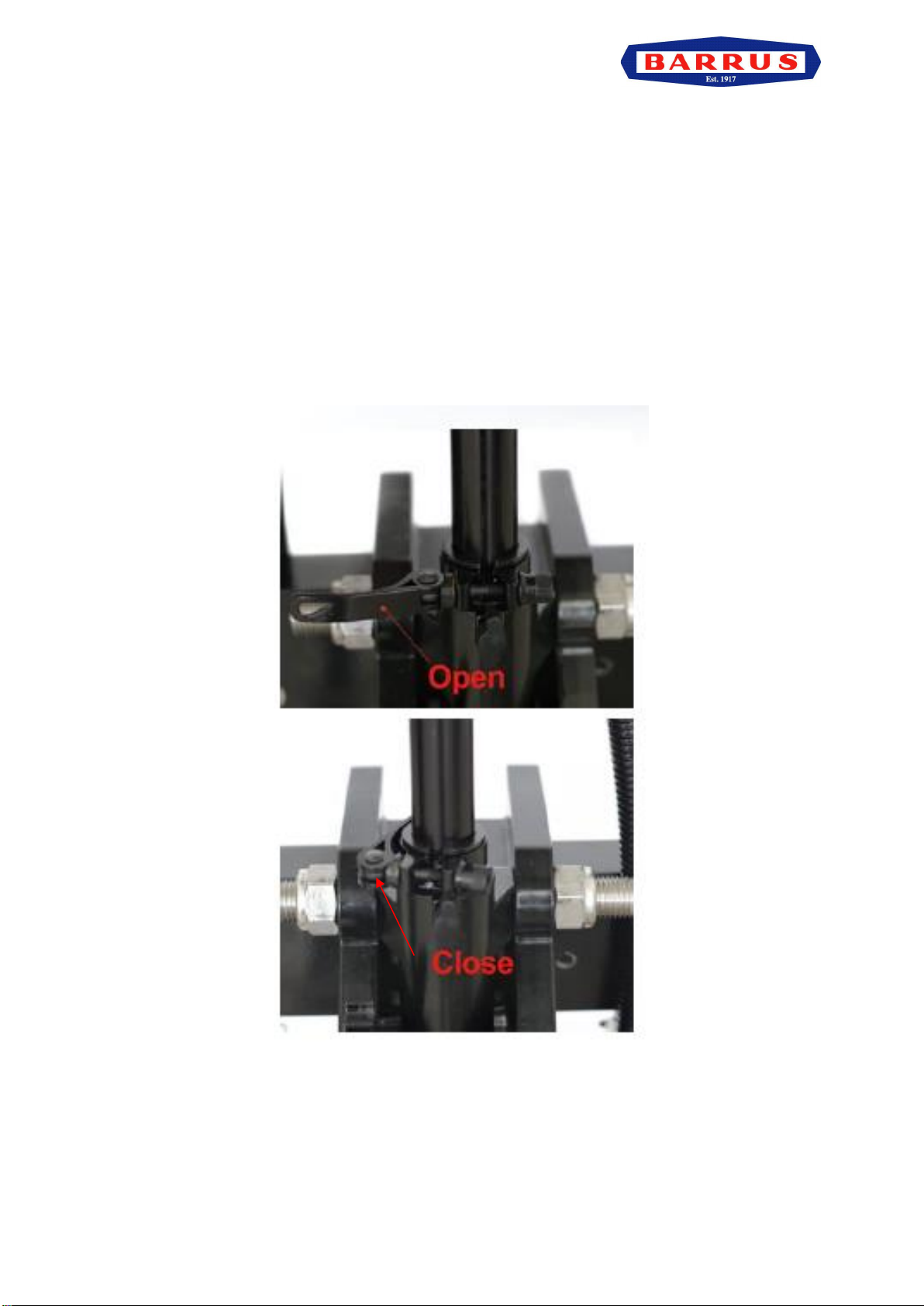
2. Adjusting the Outboard Motor Transom Height
Note: The outboard has an adjustable transom height system, there are a number of
positions to choose from between short and long shaft.
•Prior to fitting the outboard motor make sure the correct transom height is chosen for
the hull of the vessel. (see 3. Mounting of the Outboard Motor).
•To adjust the transom height, open the quick release clip and move the shaft up or
down to the required height, then close the quick release clip.
Figure 9: Adjusting the transom height
RDG603B2 –Issue 1 Page 20 of 88
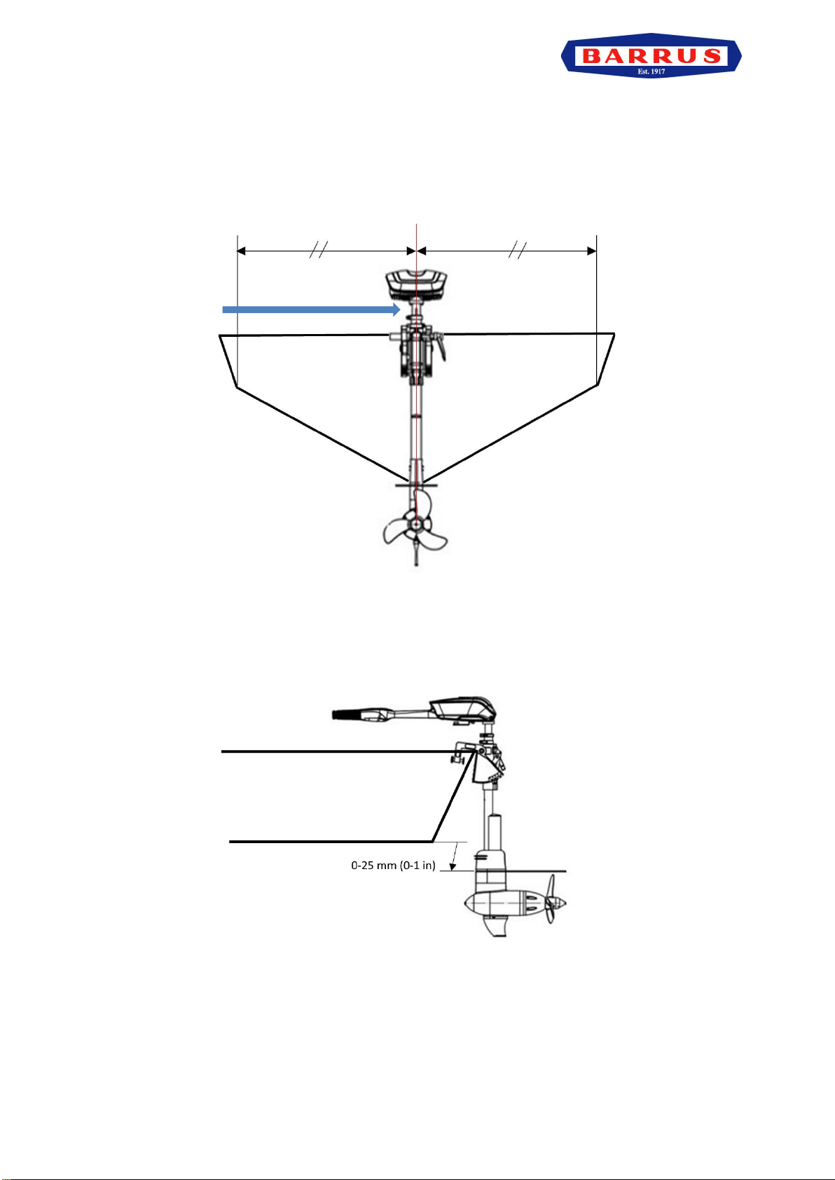
3. Mounting of the Outboard Motor
•The outboard needs to be mounted so that the boat is balanced. For single-engine
boats mount the outboard motor on the centre line (keel line) of the boat.
Figure 10: Centre Line (Keel Line)
•Mount the outboard motor ensuring the anti-cavitation plate is 25mm (1”) below the
bottom of the boat.
Figure 11: Mounting Height
Centre Line
This manual suits for next models
1
Table of contents
Other Barrus Outboard Motor manuals


