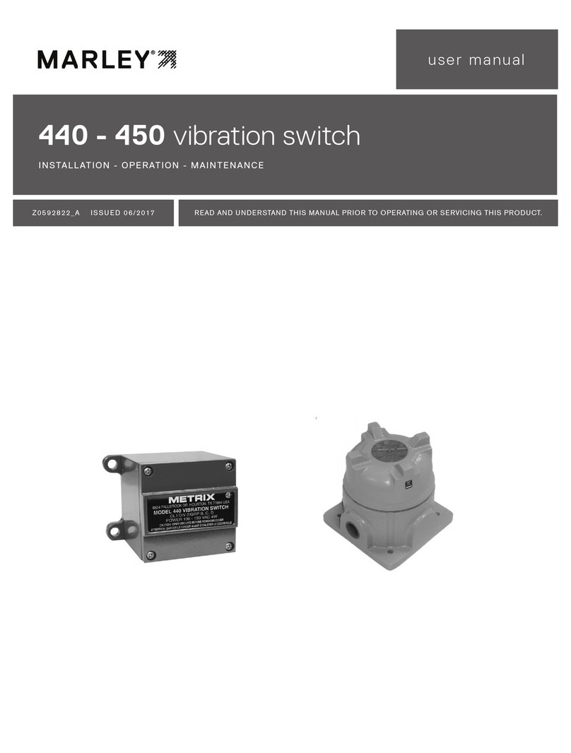
Marley IMI 686B User manual

IMI 686B vibration switch
INSTALLATION - OPERATION - MAINTENANCE
Z1070990_B ISSUED 1/2020 READ AND UNDERSTAND THIS MANUAL PRIOR TO OPERATING OR SERVICING THIS PRODUCT.
user manual

2
overview
The IMI 686B vibration switch is designed and applied specifically for cooling
tower applications. The casing is stainless steel, hermetically sealed and the
cable set is molded to the casing to prevent water vapor and contaminants
from entering the switch or its connection points.
The switch is factory programmed by SPX specifically for cooling tower vibra-
tion protection and should not be reprogrammed unless directed by SPX.
Refer to wiring diagrams in this manual for interfacing with VFD and motor
starter equipment. Typically the switch is wired to the shutdown circuit of a
VFD or motor starter. The internal switch contact is rated at 20mA, do not
exceed this value. Most VFDs have a 24 VDC low current safety circuit which
is well under the 20mA value.
The IMI 686B vibration switch has a single contact. If two contacts are required
use a Marley IB1 interface box or one of the output fault contacts on the VFD
to indicate a VFD shutdown.
Applying this switch directly in line with a motor starter operating coil may
damage the switch due to high inrush current when energizing the coil.
When applying the switch to a motor starter consider using the Marley
IB1 interface box.
General Features
• Tested in cooling tower applications by SPX engineers who rated its perfor-
mance superior to mechanical vibration switches.
• Factory-programmed by SPX specifically for cooling tower vibration protection.
• Switch may be reset remotely without entering the cooling tower.
• Repeatable trip-point includes built-in delay for startup and momentary
vibration spikes.
• Monitors vibration velocity for consistent results.
• Able to sense low frequency vibrations better than a mechanical switch.
• Integral 30' (9m) cable with molded connection at the switch protects the
connection point wiring from humidity and chemical exposure.
• NEMA4X/IP68 hermetically-sealed stainless steel enclosure withstands
harsh internal environments in a cooling tower.
• Factory installed at location near primary source of vibration.
• 2-wire combination power and control circuit adaptable to most VFD circuits.
• Wide operation temperature range: -40 to 185°F.
Caution

3
installation
Sequence of Operation
In normal operation the switch is in a N.C. (normally closed) position with
or without power applied. Once powered, the switch will remain in a closed
state allowing mechanical equipment to operate. If the switch is subjected to a
continuous high vibration level for 3 seconds or more the switch will open and
remain open in a latched state until reset back to a closed position. The three
second delay allows the tower fan to accelerate through critical frequencies
avoiding nuisance tripping.
When the switch trips, the cooling tower has been subjected to a higher than
normal vibration and should be inspected before being put back into service.
Lockout the VFD or motor starter equipment and inspect the tower's mechanical
equipment for possible vibration issues . An unbalanced driveshaft or coupling
may cause enough vibration to trip the switch.
After the vibration issue is resolved and corrected, reset the vibration switch.
To reset, power must be discharged then reapplied to the switch. When the
switch is used in a VFD or motor starter safety circuit resetting may be ac-
complished by cycling power at the VFD or motor starter line side disconnect.
Refer to the starter equipment wiring diagram or manual before attempting this
operation. When cycling power off at a VFD, keep power off for 30 seconds
allowing the VFD capacitors to totally discharge.
Cooling tower controls are typically two wire circuits so once the switch is
reset the fan motor may start automatically without warning. Make sure
personnel are in a safe location.
Torque vibration switch 2-5 ft·lbƒ(3-7 N·m) when installing or reinstalling.
Warning
Caution
Vibration Switch

4
wiring
1
2
3
4
5
6
7
8
9
10
11
12
13
14
15
16
17
18
19
20
21
22
23
24
25
26
27
28
29
30
X2
RBIO-01
BYPASS CONTROL BOARD
1PCB
+24 VDC
+24 VDC
DCOM
GND
DI1 STAR/STOP
DI2 NOT SEL
DI3 SAFETY INTERLOCK
DI4 NOT SEL
DI5 NOT SEL
DI6 OVERRIDE 1
RELAY OUTPUT 1
BYP NOT FLT
RELAY OUTPUT 2
SYS RUNNING
RELAY OUTPUT 3
SYS STARTED
RELAY OUTPUT 4
BYPASS SEL
RELAY OUTPUT 5
BYPASS AUTO
X2
X2
RS 485 CONNECTION
SCR
B+ SW1 1
A- 2
ANGD
SCR
26
27
28
J3
A
B
COM
DIP SWITCH
CONSULT MANUAL
FOR SETTING J5
1-20
SLOT 1
COOLING TOWER N.C.
VIBRATION SWITCH COMM.
BYPASS
KEYPAD
COMM.
BYPASS
DISPLAY
ON ON
Two-Wire Control Circuit using an SPST Switch
Typical connection points for the IMI 686B vibration switch used with the
E-Clipse bypass terminal strip of an ABB ACH550 VFD.
Breaking the control circuit between points 1 and 7 will disable VFD and bypass
operation. To reset the vibration switch remove incoming power to the VFD,
wait a minute or two allowing the VFD capacitors to discharge then reapply
power. At this point the switch will be in a closed state allowing VFD operation.

5
wiring
IB1 Interface Box Wiring Diagram
•Contacts shown in normal state and powered.
•Depress and hold the reset button for 15 seconds to reset the vibration switch.
A Marley IB1 interface box is available to help with connecting the vibration
switch to other equipment such as a motor starter or other VFDs. The interface
box provides a second contact which may be used to complete an alarm circuit
at the BMS, reset push button and tripped indicating light.
Mount the IB1 interface box in a convenient location for easy access by op-
erating personnel. Common locations are the cooling tower handrail or near
the tower access door at grade level.
Do not wire the vibration switch in series with the coil of an electrome-
chanical motor starter. Doing so may cause the internal switch to fail due
to coil inrush current.
Caution

6
Voltage Ratings
Q What are the available voltage ratings?
A 24 to 240 VDC/AC - 50/60Hz.
Sensor
Q Is the switch solid state?
A Yes — a piezoelectric accelerometer senses the vibration level to activate
a solid state relay when tripped. There are no mechanically moving parts.
Q Is the switch factory programmed?
A Yes — the switch is programmed for the specific use within a cooling tower.
Q Does the switch have two contacts?
A No — the switch has one contact that is factory programmed for N.C.
operation and latches open upon a trip.
Q If two contacts are required can SPX accommodate this requirement?
A Yes — an interface box with two sets of mechanical dry relay contacts is
available.
Q Is a 4-20mA vibration level output signal available?
A No — this device is only a switch.
Q Can the switch be reset remotely?
A Yes — removing the power to the switch will reset it back to normal operation.
Q Does the switch require maintenance?
A No.
Switch Mounting
Q What is the standard mounting stud?
A 1/4-28 UNF threads.
Q What is a typical mounting location?
A On a gearbox.
Q Is an explosion-proof design available?
A Yes — as a special. The explosion-proof model meets Class 1 Division 2
Groups A, B, C, and D.
Wiring
Q Is the switch furnished with a cable?
A Yes — the switch includes an integral 30' (9m) cable with blunt connection
ends.
Q Can the probe leads be extended?
A Yes — using #18 gauge 2-wire stranded copper conductor plus a shield.
SPX recommends using a junction box with terminal points to make
connections for the extension wiring.
frequently asked questions

7
Q Can the leads be cut to length?
A Yes — excessive cable should be coiled and secured if wires are not cut
to length.
Q Is the vibration switch replaceable without having to replace the cable?
A No — the cable is attached with an integrated molded connection. This
connection helps prevent water entry into the switch.
Q Does the probe lead need to be in conduit?
A The sensor cable is rated for outdoor use. Follow local codes to determine
if cable should be placed in conduit.
Integration
Q Can the switch be interfaced with the VFD in the Marley AIO control panel?
A Yes — the Marley AIO panel provides circuits to shut down the VFD and
a status contact used for a remote BMS.
Q Can the switch be interfaced with other equipment such as an
electromechanical motor starter?
A Yes — SPX can provide an interface box.
frequently asked questions

Specifications
Z1070990_B | ISSUED 1/2020
©2018-2020 SPX COOLING TECHNOLOGIES, INC. ALL RIGHTS RESERVED
In the interest of technological progress, all products are subject to design
and/or material change without notice.
IMI vibration switch
USER MANUAL
SPX COOLING TECHNOLOGIES, INC.
7401 WEST 129 STREET
OVERLAND PARK, KS 66213 USA
spxcooling.com
Part
Number Description Enclosure Rating Cable SPX Factory
Programmed Standards
2598732 Standard Vibration
Switch
NEMA4X/IP68
Stainless Steel
30' (9m) with water-
tight molded connection
at switch and flying
ends at opposite end
0.7 ips peak with
3 second delay CE
2695604
Vibration Switch
with Explosion-Proof
Enclosure
CSA Class1, Div 2
Groups A, B, C, D
Conduit head with
terminal blocks
No Cable
0.7 ips peak with
3 second delay CSA
2600177 IB1 Interface Box NEMA 4X/IP56
Fiberglass No Cable N/A CSA
UL
Standard Vibration Switch Vibration Switch with
Explosion Proof Enclosure
Table of contents
Other Marley Switch manuals
Popular Switch manuals by other brands

Cisco
Cisco CSS11501 - 100Mbps Ethernet Load Balancing... Product support bulletin

HP
HP ProCurve Switch 2650 Management and configuration guide

ELC
ELC DT229 user manual

MG
MG 10ABS instruction manual

Raisecom
Raisecom ISCOM3012GF Hardware Installation User Manual

Vertex Standard
Vertex Standard VX-4600 Series user guide