MARS-ENERGO Energoforma 3.3 User manual

OKP 43 4531
Three-phase Programmable
Waveform Generator
Energoforma 3.3
User's Manual
Edition 9
МС2.211.001 UM
2015

MARS-ENERGO
CONTENTS
INTRODUCTION.................................................................................................3
1. SAFETY REQUIREMENTS...........................................................................3
2. GENERAL INFORMATION AND OPERATION PRINCIPLE................4
2.1. APPLICATION.................................................................................................4
2.2. DESCRIPTION................................................................................................. 4
2.3. DESIGN AND OPERATION................................................................................6
3. PREPARING FOR OPERATION..................................................................8
3.1. OPERATING RESTRICTIONS.............................................................................8
3.2. UNPACKING...................................................................................................8
3.3. TURNING ON ..................................................................................................8
4. OPERATION PROCEDURE........................................................................10
4.1. PC-CONTROLLED MODE...............................................................................10
4.2. OFF-LINE MODE (CONTROL FROM MEMBRANE KEYBOARD)..........................10
4.2.1. Operator interface....................................................................................................10
4.2.2. “Standard signal” mode ...........................................................................................14
4.2.3. “Special signals” menu............................................................................................14
4.2.4. Settings menu...........................................................................................................21
4.2.5. Signal Library Menu................................................................................................22
2

МС2.211.001 UM
Introduction
The manual covers Programmable Waveform Generator Energoforma 3.3 (hereinafter re-
ferred to as the Generator) and contains the information and instructions for its operation. The
aforesaid equipment has been manufactured in compliance with Technical Specifications
TS 4345-019-499764972003-2003 and conforms to the Technical Requirements in force.
1. Safety requirements
1.1. When putting the Generator into operation and during operation, “Interbranch Rules
for Labor Safety When Operating Electrical Systems” must be observed.
The symbol
!
on the Generator's panel is intended to alert the user to the presence of important operating in-
structions. See “Warning” and “Caution” clauses in section 3.3 “Turning on”.
1.2. The Generator provides electrical safety according to Russian Standard (GOST) R
51350.
1.3. The Generator provides electrical shock protection according to Russian Standard
(GOST) R 51350-99 that corresponds to IEC 61010-1 (Category I).
1.4. Protection provided by the enclosure is per Russian Standard (GOST) 14254–96 —
IP20, Mounting Category II, pollution grade 2.
3

MARS-ENERGO
2. General information and operation principle
2.1. Application
2.1.1. Energoforma 3.3 generates single- and three-phase system of current/voltage sig-
nals according to a user-specified model that can be used for testing and adjustment of instru-
ments that measure:
Active, reactive and apparent power/energy;
Power quality parameters as per 61000-4-30 power quality measurement stan-
dard (classes A, S and B) including harmonics (up to 50th) and interharmonics;
RMS of currents and voltages within commercial frequency range.
2.1.2. The sphere of application includes mobile calibration (testing) laboratories and me-
ter/transformer test systems where the Generator is used together with reference meters, e.g.
Energomonitor 3.1K or Energomonitor 3.3T1.
2.2. Description
2.2.1. The generator is supplied as a self-contained hand-held module. The Generator's
front panel is shown in Fig. 2.1.
Fig. 2.1. Front panel
4

МС2.211.001 UM
2.2.2. The Generator is provided with three channels for generating voltages (phase volt-
ages) as well as with three independent channels for generating currents. There are two ways
for the user to specify a signal model in digital form:
By selecting one of standard signals from the device's internal memory or specifying
signal parameters (for a specific signal) using the built-in keyboard;
By selecting a signal from the Library of standard signals stored on a PC and recording
it into the Generator via RS-232 interface running the “Energoform” software;
By specifying signal parameters manually from the built-in keyboard.
Waveforms and signal parameters are viewed either on the built-in graphic LCD or PC
via “Energoform” software.
5

MARS-ENERGO
2.3. Design and operation
2.3.1. Block diagram of the Generator is shown in Fig. 2.2.
UN
Fig. 2.2. Block diagram
2.3.2. At the hart of the Generator are a Texas Instruments signal processor and FPGA
from Xilinx. Such a solution makes possible prompt upgrading of Generator’s firmware, keep-
ing its hardware intact.
The Generator employs 16-bit Digital-to-Analog Conversion (DAC). The DAC block has
six identical channels in it. They operate independently, each converting 16-bit binary input
data into analog form. 2048 points are produced every 20 milliseconds, which gives 2048 sam-
ples per period at 50Hz frequency. The DAC board produces 6 analog signals: 3 currents and
3 voltages. The current signals are galvanically isolated from each other and from other cir-
cuits, and the voltage signals are galvanically isolated from other circuits and connected by a
common wire.
The Central Processor board exercises full control over the Generator.
It produces the arrays of samples (representing point by point each of the six wave-
forms).
The array data are fed into the DAC board and converted into 3 current and 3 voltage
curves. Conversion results are stored in non-volatile memory and displayed on LCD
screen.
The Central Processor board is responsible for:
keeping of time and marking of intervals as per real-time clock;
supporting of data exchange with external devices (PCs);
receiving of data and commands from operator’s keyboard.
The keyboard is mounted on the front panel and connected to the Central Processor
board. Operator uses the keyboard to specify how the information should be displayed, to enter
6

МС2.211.001 UM
the parameters of signals to be generated (waveform, amplitude, phase shifts for currents and
voltages) etc.
2.3.3. The Power Supply unit generates voltages +5V, +3.3V, and +1.6V for the Central
Processor Board and +5V (independent power supply) for RS-232 port. It also contains a cir-
cuit that keeps output signals synchronized with power supply network (synchronization signal
represented as a 50x2048Hz meander comes to the Central Processor board).
2.3.4. Analogue current and voltage signals are taken out of the DAC board and applied
to the outputs of current and voltage amplifiers respectively.
To provide short circuit protection, a 0.25A fuse is mounted on the output of each voltage
channel.
Output ranges of the current and voltage amplifiers are processor-controlled. The proces-
sor transmits its commands to select a current or voltage output range to the relays. Ranges of
the amplifiers are also operated by commands coming from the processor.
7

MARS-ENERGO
3. Preparing for operation
3.1. Operating restrictions
If the Generator has been moved from a cold environment (with ambient temperature be-
low 20°C) into a warm one, it shall be left to stand for at least 4 hours at room temperature
before applying power, to make sure that no condensation remains inside.
Caution! The Generator shall not be used under the ingress of moisture inside its body.
Caution! Current outputs not connected to a load must be short circuited (they must not
be left without a load).
3.2. Unpacking
Check that the delivery package contains all parts specified in the Supply Agreement.
Check that the manufacturer’s seal is intact. Should anything in the package be found dam-
aged, contact the supplier immediately.
The delivery package is specified in Table 2.1 of the Equipment Certificate
(MS2.211.001 PS).
3.3. Turning on
Caution! To avoid electric shock, it is strongly recommended to connect (disconnect) the
Device to the measured circuits when they are de-energized. Otherwise, connection (discon-
nection) to the measured circuits shall be carried out by qualified service personnel in compli-
ance with local safety regulations in force.
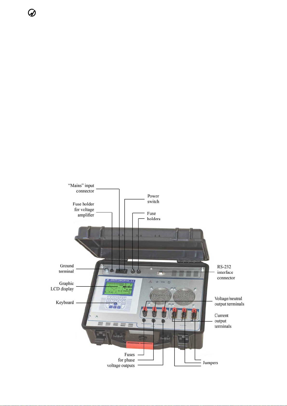
The Generator's voltage circuits have 6 terminals (UA, UB, UC) for connection to phase
voltages (and neutral); six terminals are provided for phase currents (IA, IB, IC). Current circuits
are galvanically isolated from each other and from voltage circuits. The voltage circuits are
symmetrical and have one common point (neutral conductor). All connections to measured
circuits are made via terminals located on Generator's front panel (see Fig. 2.1).
Caution! Inspect the cables. Ensure all joints are made properly to avoid overheating and
excessively high resistance.
Power the Generator from mains in the following order:
1) Connect the Generator to the device under test and reference device;
2) Plug the mains cable of the device under test and reference device to mains socket;
3) Turn on the Generator.
Caution! Before turning the Generator on, make sure that its current outputs are short
circuited (short-circuit straps are placed) or a device with the input impedance below
0.3MOhm has been connected to the Generator.
The Generator performs warm-up and initialization procedures as it is turned on. At the
conclusion of the procedure, the “power up” screen (Fig. 3.1) appears. It shows manufacturer’s
name and logo, Generator’s type and its firmware version.
8

МС2.211.001 UM
Fig. 3.1. “Power up” screen
Pressing any key will bring up the main menu (see Fig. 4.1).
To set the Generator for stable operation, it shall be kept powered for at least 30 minutes.
9

MARS-ENERGO
4. Operation procedure
Energoforma 3.3 three-phase programmable waveform generator operates in two modes:
Controlled from a PC via RS-232 running “Energoform” program;
Controlled from its membrane keyboard.
4.1. PC-controlled mode
To operate the Generator in the on-line mode, “Energoform” software package shall be
installed on a PC. The “Energoform” software works under operation systems MS Windows
98, 2000, XP, Vista and Windows 7 (32- or 64-bit architecture) supporting the Cyrillic alpha-
bet. When working in “Energoform” program, it is recommended to use the Generator to-
gether with Energomonitor 3.3T1 (or Energomonitor 3.1K) reference instrument.
The following PC configuration is recommended for proper functioning of the program:
Processor: Pentium III at 500MHz or more powerful;
At least 64Mb RAM;
At least 3Mb of disc space to install the program;
Video adapter of 1024x768 resolution;
CD drive for software installation;
Mouse or compatible pointing device;
Two free COM-ports (RS-232).
For a more convenient work with large volumes of data a more powerful computer may
be requisite.
To make the program run properly, connect serial ports of the PC to RS-232 ports of the
Generator and Energomonitor 3.3T1 (Energomonitor 3.1K) reference instrument.
On starting “Energoform” program, the Generator automatically goes to the PC-
controlled mode.
For how to work with the Energomonitor 3.3T1 (or Energomonitor 3.1K) instruments,
see the user manual for the corresponding instrument.
For how to work with “Energoform” program, see “Energoform program, User's Manual”
document.
4.2. Off-line mode (control from membrane keyboard)
In the off-line mode, the Generator is operated via its membrane keyboard.
For how to work with the Energomonitor 3.3T1 (or Energomonitor 3.1K), see the user
manual for the corresponding instrument.
Operation of the Generator in the off-line mode is described below.
4.2.1. Operator interface
Operator interface of the Generator includes an 18-button membrane keyboard and
graphic 240x128 dot matrix Liquid Crystal Display (LCD). The interface makes it possible to
select operation modes and configure signal parameters. Table 4.1 describes the keys located
on the front panel.
10

МС2.211.001 UM
Table 4.1
Functions of the keys
Key Name and Function
“0”, ..., “9” Numeric keypad: Press to type in numeric values of the field currently active
- Decimal point: press this key before entering the desired magnitude of a fractional
part;
- Press this key to enter a negative value before specifying its magnitude
i, j - Up and down arrow keys: press to scroll through various menu items;
- Press this key to scroll through the fields within a parameter setting window
g, h - Left and right arrow keys: press to increment/decrement the value of an active field;
- Press to scroll through the active status line and select a field in it
“ENT” - Enter: Press to activate a menu item or status line field;
- Press to save changes
“ESC” - Press to return to an upper-level menu without saving changes;
- Press to leave the status line
“F” - Press to activate the status line
As it is turned on, the Generator displays the screen shown in Figure 3.1. Pressing any
key will bring up the main menu (Fig. 4.1).
Fig. 4.1. Main menu
The main menu has four options:
“Standard signal”;
“Special signals”;
“Settings”;
“Signal Library”.
Whatever menu/window is on the screen, its bottom is always occupied by Generator
status line informing operator on basic modes currently in force.
Note: The operator interface may be modified with respect to the order of displaying in-
formation. The changes do not affect metrological and technical characteristics of the Generator.
Menu navigation (i.e. selection of an item) is supported by i, jkeys (the menu item
currently active is highlighted by color inversion). To enable an item (and skip to its subordi-
nate menu or parameter setting window), press “ENT”. Return to the upper-level menu is made
by pressing “ESC”. On enabling the selected menu item, it is possible either to skip to its sub-
ordinate menu or parameter setting window.
11

MARS-ENERGO
The parameter setting windows (hereinafter referred to as “the windows”) graphically
and/or textually display various parameters of the signal produced by the Generator. Each win-
dow has one or more modifiable fields in it (“the fields”). When there are several fields in the
window, i, jkeys can be used to skip from field to field. The menu item currently active is
highlighted by color inversion.
Observe the following rules when you use keyboard to change values of active modifi-
able fields within the current window:
1) Key hincreases and key gdecreases, respectively, the value of an active field. The
longer the key remains depressed, the faster the active field changes its value. Suppose
the active field can be changed cyclically (like phase shift expressed in angular de-
grees). When its growing value reaches maximum with hkey still hold down, mini-
mum value appears in the field and starts growing again. When you depress and hold
gkey, the value goes the other way round: having dropped to its minimum, it becomes
maximum and starts decreasing again. When a value in the active field is not of cyclic
nature, it can only be changed in both directions within its permissible interval.
2) By pressing number keys 0 to 9 you can immediately type in the desired value within
permissible interval established for the currently active field.
3) Suppose you modify the value of an active field formatted to have integer and frac-
tional parts. By pressing (decimal point) key you terminate integer part of the
number and change “number entry mode” accordingly. Then you specify the frac-
tional part by pressing number keys.
4) To enter a negative value into a currently active field, press (decimal point) key
BEFORE specifying the desired magnitude, provided that permissible values estab-
lished for the parameter may be negative. As soon as the decimal point key is
pressed, the field assumes a negative value with the smallest possible magnitude (i.e.
“−1” for integer fields, “−0.01” for the fields specified in 1/100 increments, etc).
Then modify the field (as described in previous paragraphs) to set a target value in it.
Having pressed “ENT”, you see (“sand glass”) icon in the Generator status line on the
bottom of the screen. This notifies you that modification is in progress, and further operation is
suspended till the end of recalculation process. To return to the upper-level menu, press “ESC”
key.
Status line
Whatever menu/window is on the screen, its bottom is always occupied by the Generator
status line (Fig. 4.2) informing operator on basic modes currently in force.
The leftmost position reflects nominal values of sub-ranges
selected in the current and voltage amplifiers. The adjacent position
marked “PRO” indicates nominal values of sub-ranges that will be
enabled when the Generator starts producing new (modified) signals
The meaning of each icon
is described below
(from right to left)
Fig. 4.2. Status line
You may activate status line by pressing “F” key in any Generator’s mode of operation.
This will give you access to change basic modes of operation. Keys g, hare used to scroll
through the active status line and select a field in it (while selected, the field is highlighted with
inverse video). When active, the active status line can be de-activated with “ESC” key.
12

МС2.211.001 UM
The meaning of each icon is described below (from right to left):
“Generation” mode:
— generation of output signals is turned on at the moment.
— generation of output signals is turned off, and the outputs have zero potentials.
To change the mode, select the corresponding icon and press “ENT”.
“Regenerate” mode (accessible only with icon):
— Pressing the “regenerate” icon brings output signals of the Generator in accor-
dance with their modified parameters. At this time, “Sand glass” icon lets
you know that modification/recalculation of the parameters is in progress, and
further operation is suspended till this comes to the end. Without the icon, the
Generator is ready to respond to your further actions, such as modification of
some other parameter.
— is displayed with .
Mode of synchronization with mains frequency (accessible only with icon):
— mains synchronization mode is enabled, and the Generator monitors mains fre-
quency and produce its output signals accordingly.
— no monitoring of mains frequency is maintained at the moment. The Generator
produces its output signals in accordance to the frequency specified by the “fre-
quency” parameter (Fig. 4.8)).
To enable a mode, select the corresponding icon and press “ENT”.
The position marked ▷reflects nominal values of sub-ranges selected in the current and
voltage amplifiers. The adjacent position marked PRO- indicates nominal values of sub-ranges
that will be enabled when the Generator starts producing new (modified) signals. As soon as
the “generation” or “regeneration” command is executed, the current nominal values
become equal to these “programmed” values.
“Sand glass” icon displayed in the inverse video (Fig. 4.3) informs you that modifica-
tion/recalculation of the parameters is in progress. Further operation is suspended till this
comes to the end. Without the icon, the Generator is ready to respond to your further actions.
Fig. 4.3 Generator status line
(modification/recalculation in progress)
If an additional context-dependent function is included in the current menu/window, the
function name appears on the active status line and gives access to that function (Fig. 4.4).
Press “ENT” to enable the function.
Fig. 4.4. Generator status line with additional function in it.
13

MARS-ENERGO
4.2.2. “Standard signal” mode
The mode makes Generator produce pure sine waveforms on its outputs. Angles between
phase voltages are set to 120°.
You can use the window shown in Fig. 4.5 to specify:
Fundamental (1st harmonic) frequency — from 42.50 to 70.00Hz in 0.01Hz steps;
Phase shifts between currents and voltages for each phase — from –179.99° to
+180.00° in 0.01° steps);
Values of voltage — from 0 to 268V in 0.001V steps);
Values of current— from 0 to 8A in 0.00001A steps).
Checkboxes below IA, IB, ICfields allow you to toggle switches that are used to set off
(zero) phase currents as desired. A switch is selected by g, hkeys, then toggled by “ENT” key.
Fig. 4.5. Parameter setting window for Standard signal
New wave shapes are recalculated by pressing “ENT”. It may take long time to recalcu-
late the parameters (up to 5s). The time of recalculation is determined by the selected wave
shapes and the number of channels for which the parameters are recalculated. When recalcula-
tion is in progress, the status line displays icon.
Note: All changes made in the “Standard signal” mode are automatically extended to the
“Subharmonics” (section 4.2.3.2) and “Phase Control” (section 4.2.3.3) modes and vice versa.
4.2.3. “Special signals” menu
“Specific signals” menu (Fig. 4.6) has six options:
Programmed waveform;
Subharmonics;
Phase control;
Dips and swells;
Flicker;
Library.
Fig. 4.6. “Specific signals” menu
14

МС2.211.001 UM
4.2.3.1. “Programmed waveform” menu
This option (Fig. 4.7) makes it possible to set signals on Generator outputs to any desired
parameter values (within permissible limits established for each parameter):
Frequency;
Phase angles;
Wave shape;
RMS values.
Additionally, the “Interharmonics” mode is turned on/off here.
Fig. 4.7. “Programmed waveform” menu
Setting frequency
The “Frequency” item, when enabled, opens the window (Fig. 4.8) where you can set
fundamental frequency (i.e. frequency of the first harmonic) of the desired three-phase volt-
age/current system ( ). When the mains synchronization mode is enabled ( ), output fre-
quency is determined by mains frequency. Otherwise (with “eye” icon), the Generator ignores
frequency specification entered in this window.
Fig. 4.8. Parameter setting window for signal frequency
“Frequency” is the only modifiable field within this window. It can accept values of
42.50 to 70.00Hz specified in 0.01Hz increments. As you adjust frequency, the window dis-
plays the value just entered, and sample oscillogram immediately below.
Setting phase angles
By enabling “Phase shifts” item you open the window (Fig 4.9) where you can set phase
shifts between voltages of different phases as well as between currents and voltages within
each phase (by definition, phase angles between channels are considered to be these between
respective first harmonics).
15

MARS-ENERGO
Fig. 4.9. Parameter setting window for phase angles
Six modifiable fields of the above window correspond to various angles, as applied to the
first harmonics of signals to be generated. The fields are modified within the range of –179.99°
to +180.00°in 0.01°increments. The values can be set by cycling through the range.
All settings currently selected are pictured on a vector diagram in the left part of the
screen. Vectors on the diagram reflect each modification. Arrows (pointed heads) only appear
on the vectors that form the angle selected at the moment, while other vectors remain headless.
Setting signal shapes
Screens representing wave shapes of desired signals may be of 4 types:
Oscilloscope;
Spectrum (linear);
Spectrum (logarithmic);
Harmonics phases.
To skip to an alternative representation, use additional function of this window named
“Change view”. The function is enabled via its highlighted name in the status line.
By enabling “Waveshape” item you can set the desired shape of a signal in each of six
Generator’s channels.
The “Oscilloscope” option (Fig. 4.10) displays the signal under review in the form of tra-
ditional oscillogram. The view of the oscillogram depends on whether the “Interharmonics”
mode is turned on or off.
Fig. 4.10. “Waveshape” window in the form of oscillogram
(left part — “Interharmonics” mode is off; right part — “Interharmonics” mode is on)
The window has 4 editable fields:
Number of the harmonic selected (“n” field):
“Interharmonics” mode is off. Possible values are selected from the sequence: 1, 2, …,
49, 50.
“Interharmonics” mode is on. Possible values are selected from the sequence: 0.5;
1; 1.5; 2; …, 50; 50.5.
The required value is selected with g, hkeys;
16

МС2.211.001 UM
amplitude ratio of the harmonic (“Un” or “In” field, the value is set as a percentage of
the 1st harmonic):
“Interharmonics” mode is off. Values are set within the range of 0 to 100.00 % in
0.01 % increments.
“Interharmonics” mode is on. Values are set within the range of 0 to 15.00 % in
0.01 % increments.
relative phase of the harmonic (“ϕ1–n”, the value is set as a percentage of the 1st har-
monic within the range of –179.99°to 180.00°in 0.01°increments);
symbolic name of the channel (to switch over 6 channels).
The “Spectrum (linear)” option (Fig. 4.11) represents spectrogram of the signal in the
channel under review drawn in linear scale.
Fig. 4.11. “Waveshape” window
with linear spectrum of amplitudes
The “Spectrum (logarithmic)” option (Fig. 4.12) displays the spectrogram of the signal in
the channel under review drawn in logarithmic scale (in decibels, dB), this only affects graphi-
cal part of the window. The value in its modifiable field named “amplitude ratio of the har-
monic” (Un or In) are still displayed and edited in linear scale (as a percentage of the 1st har-
monic).
Fig. 4.12. “Waveshape” window
with logarithmic spectrum of amplitudes
The “Harmonics Phase Shift” option (Fig. 4.13) displays the spectrum of phase shift an-
gles, each determined relative to the first (fundamental) harmonic of the signal in the active
channel.
17

MARS-ENERGO
Fig. 4.13. “Harmonics Phase Shift” window
with spectrum of phase shift angles
“Linear spectrum”, “Logarithmic spectrum” and “Harmonics phase shift” windows con-
tain 2 editable fields:
number of the harmonic selected (“n”, setting is made with i, jkeys, which makes
the cursor move to the spectral line corresponding to the harmonic selected;
“amplitude ratio of the harmonic” (“Un” or “In” fields in the “Spectrum (linear)” and
“Spectrum (logarithmic)” windows; “relative phase of the harmonic” (“ϕ1–n” in the
“Harmonics phase shift” window.
The channel under review can only be selected in the “Oscilloscope” window.
Setting RMS values
The “RMS values” item, when enabled within “Special signals” submenu, opens the
window (Fig. 4.14) where you can set the desired RMS value for the first harmonic of each
output signal.
The window header is self-explanatory: “RMS values of 1st harmonics”. Six modifiable
fields at the centre of the window correspond to six channels of the Generator. The fields dedi-
cated to voltage channels can accept values 0 to 268V; these standing for current channels
have 0 to 8A for permissible range. When being modified, all fields are incremented with step
equal to one unit of least significant decimal place (0.001V for voltage channels and 0.00001A
for current channels).
Fig. 4.14. “RMS values” window
Turning “Interharmonics” on/off
To toggle between the “Interharmonics” mode on and off, select the corresponding option
in the “Programmed waveform” menu and press “ENT”: “ON” or “OFF” status will appear to
the right of the field.
Note: When the mode is “ON”, recalculation time will be extended.
18

МС2.211.001 UM
4.2.3.2. “Subharmonics” mode
In the “Subharmonics” mode, it is possible to set parameters for signals on Generator’s
current outputs IA, IB, IC. One period of such a signal is outlined on the diagram (Fig 4.15).
Fig. 4.15. Shape of a signal generated in “Subharmonics” mode
(with period T)
You can use the window pictured on Fig. 4.16 to specify:
fundamental frequency (i.e. the frequency of the first harmonic);
phase shift between current and voltage, one and the same for each phase;
current and voltage values.
Checkboxes below IA, IB, ICallow you to toggle switches that you can use to set off
(zero) phase currents as desired. A switch is selected by g, hkeys, then toggled by pressing
“ENT” key.
Angles between phase voltages are set to 120°.
Fig. 4.16. Parameter setting window for “Subharmonics” mode
4.2.3.3. Phase control mode
In the “Phase Control” mode, it is possible to set parameters for specially-shaped signals
on current outputs IA, IB, IC. One period of such a signal is outlined on the diagram (Fig 4.17).
Fig. 4.17. Shape of a signal generated in “Phase Control” mode
(with period T)
19

MARS-ENERGO
You can use the window pictured on Fig. 4.18 to specify:
fundamental frequency (i.e. the frequency of the first harmonic);
phase shift between current and voltage, one and the same for each phase;
current and voltage values.
Checkboxes below IA, IB, ICallow you to toggle switches that you can use to set off
(zero) phase currents as desired. A switch is selected by g, hkeys, then toggled by pressing
“ENT” key.
Angles between phase voltages are set to 120°.
Fig. 4.18. Parameter setting window for “Phase control” mode
4.2.3.4. “Dips and swells” mode
You can use the window pictured on Fig. 4.19) to set a number of parameters that define
dips and/or swells (referred to as “the events”) to be introduced in output signal generated by
voltage channels:
total number of events n = 0 to 100 000;
duration of one event t = 0 to 600s;
event repetition period T = 0 to 600s (0.001s increment); T cannot be less than t);
first event shift in time, relative to the moment of triggering (time delay between issu-
ing the command to generate the output signal, and the occurrence of first event)
tn= 0 to 600s, 0.001s increment);
phase shift of the event (ϕn= –179.99°to 180.00°in 0.01° increments; this parameter
is only valid when half-cycle referencing (1/2T base) option is enabled;
half-cycle referencing (1/2T base). This characteristic of the event means that each
event is triggered in step with nearest half-cycle of fundamental frequency. This kind
of synchronization is recommended in conjunction with aforesaid “phase shift of the
event” (φnother than zero);
dip depth value (Un < 100%) or swell height value (Un > 100% ) for each phase (UA,
UB, UC) within the range of 0 to 200% in 0.01% increments).
Fig. 4.19. Parameter setting window for “Dips and swells” mode
In the “Dips and swells” mode, voltage range is always set to 220V.
20
Table of contents
Popular Measuring Instrument manuals by other brands

CARLO GAVAZZI
CARLO GAVAZZI EM24 IS-R2-O2 Series user manual

KROHNE
KROHNE OPTISONIC 6300 quick start

PCB Piezotronics
PCB Piezotronics 357B33 Installation and operating manual

Burkert
Burkert 8203 operating instructions

EUTECH INSTRUMENTS
EUTECH INSTRUMENTS WATERPROOF PHTESTR 2 PH TESTER instruction sheet

Siko
Siko DE10P manual