Marshall Amplification AUTOBROIL 2424 User manual

OWNER’S MANUAL
2424, 121224 AUTOBROIL™
145861 Rv101105
Copyright© 2005 Marshall Air Systems, Inc.
All Rights Reserved.
1
THIS MANUAL APPLIES TO BROILERS WITH S/N 3284 FORWARD
MODEL: 2424 121224 AUTOBROIL™
TABLE OF CONTENTS
I. BROILER SETTINGS ..................................................................................................... .......................1
II. EQUIPMENT INSTALLATION ........................................................................................ .......................2
Pre-Installation.......................................................................................................... .......................2
Equipment Location .................................................................................................. .......................2
Electrical Information ................................................................................................ .......................2
III. OPERATING INSTRUCTIONS ....................................................................................... .......................3
Pre-Operation Check ................................................................................................ .......................3
Broiler Adjustment .................................................................................................... .......................3
Toaster Operating Instructions ................................................................................. ................... 3-4
Toaster Shut-Off Instructions.................................................................................... .......................4
Toaster Conveyor Speed.......................................................................................... .......................4
Operation of 6-Button Controller............................................................................... ................. 5-11
IV. SCHEDULED MAINTENANCE....................................................................................... .....................12
Daily Cleaning Procedures ....................................................................................... ............... 12-13
Monthly Cleaning Procedures................................................................................... .....................13
Quarterly Cleaning Procedures and Preventive Maintenance.................................. ............... 13-14
V. TROUBLE SHOOTING ................................................................................................... ............... 14-18
VI. ASSEMBLY & DISASSEMBLY INSTRUCTIONS........................................................... ............... 18-19
VII. REPLACEMENT PARTS ................................................................................................ ............... 19-21
ILLUSTRATIONS
Overall Dimensions...................................................................................................……….. .......... Figure 1
Exploded View - Removable Parts ........................................................................... ....................... Figure 2
Exploded View - Internal Parts ................................................................................. ....................... Figure 3
Exploded View - Drive System ................................................................................. ....................... Figure 4
Drive System Detail .................................................................................................. ..................... Figure 4A
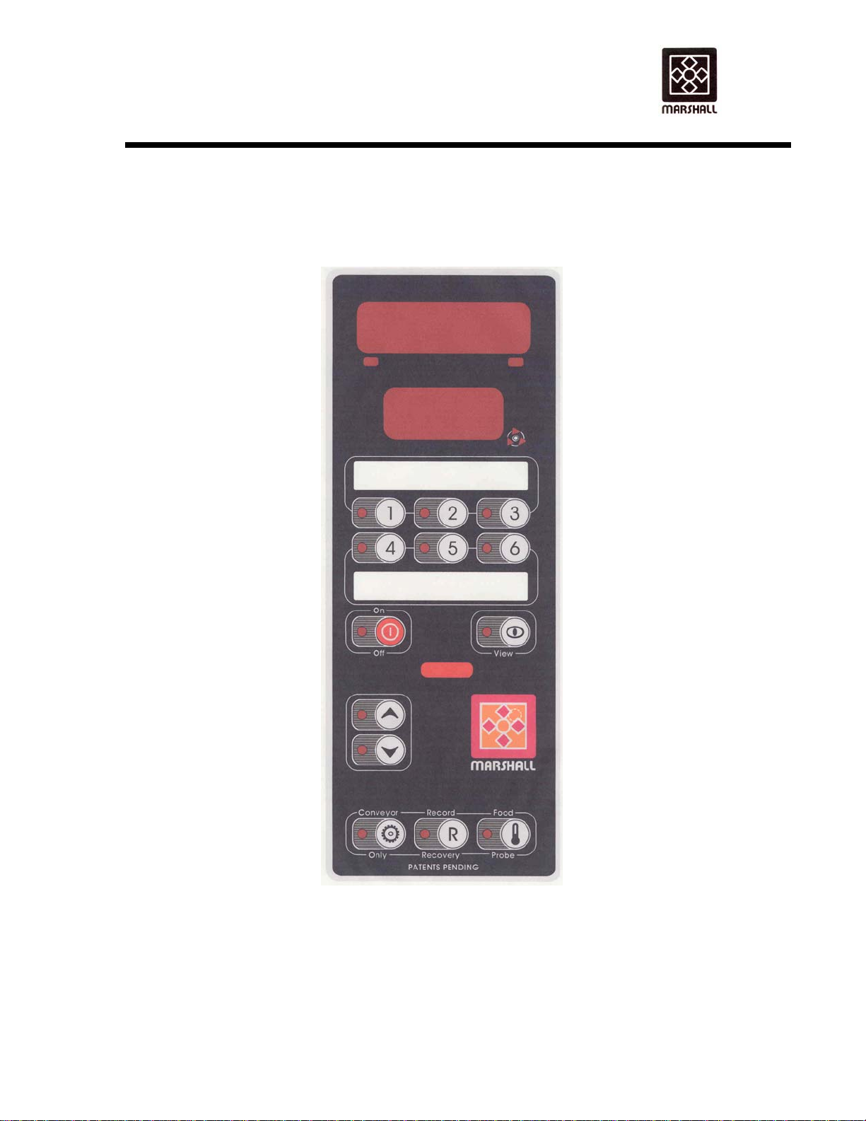
Control Panel With 6-Button Control......................................................................... ....................... Figure 5
Conveyor Axle Scraper............................................................................................. ....................... Figure 6
Spark Guard Installation…………………………………………………………………. ........................ Figure 7
Broiler Arm Extension 2424 ...................................................................................... ........................ Figure 8
Broiler Arm Extension 121224 .................................................................................. ........................ Figure 9
Broiler Idler Shaft Asby ............................................................................................. ...................... Figure 10
Toaster Platen Asby LH............................................................................................ ...................... Figure 11
Toaster Platen Asby RH ........................................................................................... ...................... Figure 12
Speed Control Circuit Board ..................................................................................... ...................... Figure 13
Fuse Location ........................................................................................................... ..................... Figure 14
Toaster Platen Heat Control ..................................................................................... ..................... Figure 15
Element Locations .................................................................................................... ..................... Figure 16
Wiring Schematic 121224……………………...(208V, 3PH, 60 AMP w/6-Button Control) Drawing #145703
Control Panel Quick Guide……………………………………………………...........................Drawing #145747

OWNER’S MANUAL
2424, 121224 AUTOBROIL™
145861 Rv101105
Copyright© 2005 Marshall Air Systems, Inc.
All Rights Reserved.
2

OWNER’S MANUAL
2424, 121224 AUTOBROIL™
145861 Issued111104
Copyright© 2004 Marshall Air Systems, Inc.
All Rights Reserved.
1
I. BROILER SETTINGS
AUTOBROIL™
MODEL: 2424 121224
MODEL NUMBER:____________________________________________________________
SERIAL NUMBER: ____________________________________________________________
ELECTRICAL SUPPLY: _________________________________________________________
SCHEMATIC NUMBER___________________ REV. _________
TOASTER PLATEN TEMPERATURE SETTING (425°F IS FACTORY SETTING)_______________
MENU SETTINGS: TEMPERATURE
RECIPE KEY SPEED TOP BOTTOM
1 ______________ _______ _______
2 ______________ _______ _______
3 ______________ _______ _______
4 ______________ _______ _______
5 ______________ _______ _______
6 ______________ _______ _______
START-UP TECHNICIAN: __________________________________________________________
START-UP DATE: ________________________________________________________________
COMMENTS: ____________________________________________________________________
_____________________________________________________________________________
_____________________________________________________________________________
_____________________________________________________________________________
_____________________________________________________________________________
_____________________________________________________________________________

OWNER’S MANUAL
2424, 121224 AUTOBROIL™
145861 Issued111104
Copyright© 2004 Marshall Air Systems, Inc.
All Rights Reserved.
2
II. EQUIPMENT INSTALLATION
PRE-INSTALLATION
1. After uncrating the Autobroil™unit, inspect for shipping damage. Check that the controller, switches, and
components are intact on the electrical cabinet front. Set the Autobroil™in place and use the plastic bag
to protect it from the debris and trash of building construction. Check that sideskins have not been dented
or damaged by the carrier. If damaged, notify your freight carrier immediately to file a concealed damage
claim, following the instructions attached to the outside of the shipping crate. Your warranty will not cover
freight damage.
2. Because this unit is required to be power fan exhausted, it is necessary to provide adequate make up air
equal to the amount of air removed. In addition to this, any other exhausts, flues, or air removal systems
must be taken into consideration. Examples of this are heat removal fans or hot water heater flues.
EQUIPMENT LOCATION
1. Position Autobroil™to properly align with exhaust hood. Check name plate for clearance requirements.
2. The hood/ventilator for the catering equipment should be located in accordance with the National Fire
Protection Association Standard #96, "Removal of Smoke and Grease-Laden Vapors from Commercial
Cooking Equipment" and any local applicable requirements.
3. For proper installation, the minimum clearance from combustible construction is 6" (152mm) from sides
and 6" (152mm) from back.
4. Adequate clearance should be maintained to allow easy access to loading and unloading areas of the
machine.
5. For servicing, unit must be moved 2' (610mm) clear from all construction.
ELECTRICAL INFORMATION
1. The Electrical Schematic is inside the electrical cabinet, and a copy is also included at the back of this
manual. Make certain the supply voltage and number of supply conductors agrees with the Electrical
Schematic. The load-carrying conductors should be sized according to the loads shown on the Electrical
Schematic per local codes and the National Electrical Code, ANSI/NFPA 70 -Latest Edition. If the broiler
is supplied with a cord, it will be type 4/4 or 6/4 SO 90 DEG C or higher, L1, L2, L3 and ground (See
electrical schematic for proper cord size). The cord will be approximately 9 feet long.
2. On a new electrical service - MAKE CERTAIN THAT VOLTAGE IS WITHIN 10% OF THE UNIT'S
RATED VOLTAGE. Appliance should be protected by a properly-sized circuit breaker furnished from the
main building circuit panel.
3. There is an Electrical Schematic located in the back of this Owner's Manual and also inside the
electrical cabinet of the machine.

OWNER’S MANUAL
2424, 121224 AUTOBROIL™
145861 Issued111104
Copyright© 2004 Marshall Air Systems, Inc.
All Rights Reserved.
3
III. OPERATING INSTRUCTIONS
PRE-OPERATION CHECK (START-UP)
Before operating your Autobroil™, make a quick check of critical items as follows:
1. Check that no "binding" and resultant conveyor overloading is present. With the electrical
connections complete and with the electrical cabinet door secured shut, turn the broiler "ON" and run
the conveyors. Adjust the speed control for mid-point speed. The conveyor should move forward in
smooth unaltered motion. Shut down immediately if there is any evidence of "binding" or other
mechanical blockage.
2. Proper conveyor operation is when the amperage draw in the white or black motor lead from the
circuit board (Figure 4) to the motor cord measures .15 DC amps or less. To check amperage the
cabinet door will need to be open. THIS PROCEDURE SHOULD ONLY BE PERFORMED BY A
QUALIFIED ELECTRICIAN.
3. The Autobroil™was tested at the factory before shipping so excessive amperage will indicate
conveyor binding caused by shipping damage. Remove the roller chain (Figure 4) driving the
conveyor in question and move the conveyor by hand. Loosen the sprockets (Figure 4) that drive the
various axles and reposition them by 1/32" (1mm) until the conveyor tightness is eliminated. Twenty-
five inch pounds of torque is required to drive a properly set up conveyor.
4. After the conveyor checkout is complete, turn on the heat switch. All heater elements should glow
red. After the unit is up to temperature, these two elements will cycle. For trouble shooting problems,
see Section V. CAUTION: NEVER RUN HEAT WITHOUT CONVEYOR ON AS THIS CAN WARP
THE CHAIN.
5. Before first use, and after any special cleaning, it is necessary to "season" the BROILER chain. This
is done by bringing the broiler chain to operating temperature and applying liquid shortening from a
saturated cloth over the full width of the broiler chain while the chain makes five or six complete
revolutions.
6. Check to see that the three heat reflectors (Figure 3) are in place.
BROILER ADJUSTMENT
The Autobroil™requires 30 minutes to reach stable temperature. After this time lapse, the conveyor speed
can be set to properly cook the product. The control will display “READY” when the broiler reaches cooking
temperature.
TOASTER OPERATING INSTRUCTIONS
1. The temperature control is located behind the right side lift-off cover. The control is factory-preset for
425ºF (218ºC).
2. Adjust the bun platen height over the conveyor so the platen touches the bun as it is moved under the
platen. To lower platen, turn the knob counter clockwise. To raise platen, turn the knob clockwise. This
produces a caramelized surface. If the platen is adjusted too low, the bun will be crushed.

OWNER’S MANUAL
2424, 121224 AUTOBROIL™
145861 Issued111104
Copyright© 2004 Marshall Air Systems, Inc.
All Rights Reserved.
4
TOASTER SHUT-OFF INSTRUCTIONS
1. The toaster section will continue to operate when the main heating (cooking) section of the broiler is on.
DURING A PROLONGED POWER FAILURE, NO ATTEMPT SHOULD BE MADE TO OPERATE THE
CATERING EQUIPMENT.
TOASTER CONVEYOR SPEED
1. The toaster conveyor is the lower conveyor on the broiler. This conveyor is linked to the main cooking
chamber broiler and does not have a separate speed control for the toasting section. For broilers without
computer controls, he toasting section is controlled by adjusting the toasting section temperature, using
the control located behind the right side lift-off cover.

OWNER’S MANUAL
2424, 121224 AUTOBROIL™
145861 Issued111104
Copyright© 2004 Marshall Air Systems, Inc.
All Rights Reserved.
5
OPERATION OF 6-BUTTON CONTROLLER
1. USER INTERFACE
The following is the user interface layout. This control is located on the front of the broiler on the
right side.
The Control Panel illustration above shows a typical control interface layout. Also See Figure 5 for
Description of the Buttons. A Control Panel Quick Guide is located at the end of this manual.

OWNER’S MANUAL
2424, 121224 AUTOBROIL™
145861 RV050405
Copyright© 2005 Marshall Air Systems, Inc.
All Rights Reserved.
6
TIME AND DATE SETUP (USED ONLY ON BROILERS WITH FOOD PROBE OPTION)
When the controller is in Off mode, the system Time and Date can be adjusted by pressing the Off
Key for 10 seconds. The time is displayed on the 1st line, and the HH is blinking. Using the Up and
Down Keys, the hours are changed. Pressing the View Key moves the “focus” to the MM. Use the
Up/Down Keys to adjust. By pressing View Key again, HH:MM are replaced by DD/MM (or
MM/DD, depending on setting of temperature units) (1st line) and YY (2nd line). Use the View Key
to travel from one setting to another, and use the Up/Down Keys to modify. The View Key will
return to HH:MM. Pressing the Off Key again stores the new Time and Date, and returns to Off
mode.
ON/OFF KEYS
A normal press of this key turns on the controller. This causes the unit to start heating the
elements and running the motors at the slowest recipe speed found (overcooked food is safer
than undercooked food). This recipe is automatically selected (its corresponding LED lights up)
and the temperature set point is the one defined by this same recipe. At any time in On mode, the
user can change the selected recipe. When initially turned On, the unit will scroll PREHEAT on
the 1st line until the broiler comes up to temperature. After this time, unit will display either
READY, LOW, OR HIGH, depending on the current temperature readings.
A 3-second long press of the On/Off key turns off the unit. When the unit is turned Off, the Heater
Kill output is deactivated to disable power to heating elements. The 1st line will then blink HOT for
the Cool Down period (heating elements are off, but the conveyor motor is still running at the
fastest speed allowed by the unit). At that point, the unit will then simply display OFF, and all
outputs will be disabled.
RECIPE KEYS
Recipes are defined by a time and a temperature. The time basically sets the conveyor speed.
The top three (3) recipe buttons are for the left conveyor belt and the bottom three (3) buttons are
for the right conveyor belt.
When the unit is READY, a simple press of the recipe key will activate the selected recipe speed
and temperature (LOW and HIGH conditions may or may not be triggered).
When a specific recipe must be changed, keep its button pressed for 3 seconds, until the 1st
parameter name SET COOK TIME scrolls on the 1st line. The recipe as well as the Up/Down
LED’s will also blink indicating that they can be used. Pressing either Up or Down the 1st time
simply makes the display switch to the parameter’s value (preceded by an arrow, as in ►4.25 , to
indicate a changeable value). Subsequent presses will then modify the parameter. If Up or Down
is not pressed in 5 seconds, the display resumes scrolling the parameter name.
Each recipe has 3 programmable parameters. To switch from one to the next, press the recipe
key. After the last parameter is programmed, the unit resumes normal operation.
-SET COOK TIME,
-SET TOP TERMPERATURE,
-SET BOTTOM TEMPERATURE.
By default, all recipes are set as follows:
Cook time: 5.00

OWNER’S MANUAL
2424, 121224 AUTOBROIL™
145861 Issued111104
Copyright© 2004 Marshall Air Systems, Inc.
All Rights Reserved.
7
Top temperature: 1325 ºF
Bottom temperature: 1250 ºF
VIEW KEY
The View key allows a user to view actual or programmed system parameters. Changes cannot
be made just by using this key.
In normal operation (On mode), pressing the View key will start scrolling the message BOTTOM
TEMPERATURE; also, the View and Up keys blink, indicating they can be used. If the broiler has
two conveyors, the down key also blinks. The 2nd line shows the current conveyor speed of the
illuminated recipe key. Pressing the Up key causes the 1st line to toggle between the message
and the actual temperature value. The down key will cycle to the recipe for the second conveyor.
A final press of the View key resumes normal operation.
When simply pressing the view key (not holding for 3 seconds), the 2nd line always shows the
current conveyor speed. If the unit is Off, or Hot, the conveyor speed is not shown.
A 3-second long press of the View key allows users to see the current recipe programs without
actually being able to change them. After this delay all 6 recipe LED’s blink, allowing the user to
select the wanted recipe. Once a recipe is selected, the procedure is the same for all recipes. The
1st parameter shows COOK TIME. By pressing the Up key, the user can view the value that is
currently programmed (but cannot change it). In 5 seconds the unit returns to the parameter
name. Pressing the Recipe key a 2nd time will bring up BOTTOM TEMPERATURE. Again, using
the Up key, the value can be seen. In 5 seconds, the unit returns to the parameter name.
Pressing the recipe key one last time returns the unit to normal operation.
CONVEYOR ONLY KEY
The Conveyor Only key is only accessible from the Off state. This key allows the conveyor to be
used without any heating. Press the Conveyor Only Key, then press the View Key. Press the Up
arrow to start the left conveyor moving. Do not run the conveyor faster than 230 on the display.
Press the Conveyor Only key to return to Off state. To start the other conveyor moving, press the
View button 2 times, then press the Up Arrow to the desired speed. This does not change the
programmed speed.
The parameter name SPEED is displayed on the 1st line. The current speed is displayed on the
2nd line (expressed as a time). The flashing triangle indicates the speed can be changed using
the Up and Down keys. Exit this mode by pressing Conveyor Only a 2nd time; however, the speed
selection is lost (i.e. the 1st speed used in READY mode is always the slowest recipe speed).
The display shows the theoretical motor shaft speed (divided by 100) on the top display, and the
real tachometer input (divided by 100) on the 2nd line. The theoretical value is simply derived
from the requested speed (in terms of time) and the programmed K value. The real value is
exactly that, the value coming in from the external tachometer. In an ideal world, the top and
bottom lines should read very close to the same value.
The next screen of data in the Conveyor Only mode is the real RPM coming in from the
tachometer input. By pressing the View key a 2nd time, this is displayed on the 1st line (which has
enough characters to display the information, as in the previous screen). A third and final press of
the View key returns to the standard Conveyor Only screen with SPEED on the 1st line.

OWNER’S MANUAL
2424, 121224 AUTOBROIL™
145861 Issued111104
Copyright© 2004 Marshall Air Systems, Inc.
All Rights Reserved.
8
RECORD/RECOVERY KEY
A recovery time is the time required for the temperature to go from 200°F to 800°F. A log exists
for each heater (top and bottom). This is useful for service and HACCP purposes.
Do not press the Recovery Key while in the conveyor only mode. This key is available anytime
the broiler is in normal operation. When pressed, the controller will list a log of the last 3 recovery
times.
When the Recovery Key is pressed, the controller will successively display TOP 1, TOP2, TOP 3,
BOT 1, BOT 2, AND BOT 3 recovery times, “1” being the most recent ramp logged. To actually
see the logged time, press the Up key. After the last set is seen (BOT 3), the unit resumes
normal operation.
FOOD PROBE KEY – THE FOOD PROBE IS OPTIONAL AND MAY NOT BE INSTALLED ON
ALL BROILERS
This key is useable only when the unit is On (and the Food probe is enabled in the Low-level
programming). It is accessible in 2 modes: automatic or manual. In manual mode, it is up to the
user to press the Food Probe key to initiate a log, whereas, the automatic mode will remind the
user (up to 6 times a day) to take a sample. Even in automatic mode, the user still has the
capability to log extra samples manually as he/she wishes.
To do a manual log, the user must first make sure the temperature probe is correctly connected,
and then press the Food Probe Key.
Step #1
This step prepares the controller for logging.
Display: SELECT RECIPE TO LOG is scrolled and recipe LED blink.
Sound: None.
User Action: Select the Recipe corresponding to the sample that will be probed.
Step #2
This step starts the logging as such, and gives the user time to set up for the sampling.
Display: Shows INSERT PROBE. Actual temperature can be seen when Up key is
pressed. The Up key and Record LED blink.
Sound: None.
User Action: Insert the Food Probe into the sample according to local sanitary codes and normal
restaurant procedures.
Step #3
In this step (basically a continuation of Step #2), the temperature continues to be displayed for the
user. Nothing is being logged yet. The user must wait until a certain temperature is reached (that
depends on what is being sampled (chicken, beef, etc.), as well as specific restaurant
procedures).
Display: The 1st line displays the temperature currently measured by the Food Probe. The
Record key LED also blinks.
Sound: No particular sound.
User Action: Keep Food Probe inserted. When temperature reaches a specific point (known to

OWNER’S MANUAL
2424, 121224 AUTOBROIL™
145861 Issued111104
Copyright© 2004 Marshall Air Systems, Inc.
All Rights Reserved.
9
the user), the user presses the Record button.
Step #4
When the Record button was pressed, 2 things happened: the “Start Temperature” was stored, and
the equalization timer was started. The controller now waits for the timer countdown to finish.
Display: The 1st line continues to display the temperature currently measured by the Food Probe.
However, there are no keys that function at this point.
Sound: A beep every 1 second until 5 seconds before end of timer. During last 5 seconds, beeps
accelerate to 2 beeps per second.
User Action: Keep Food Probe inserted.
Step #5
In this last step, the actual log is written to memory. The temperature now displayed is logged as the
“End temperature.”
Display: Last temperature read when timer reached zero is displayed until Food Probe Key is pressed
again. This exits Food Probe.
Sound: None.
User Action: Remove probe, and press any key to resume normal operation.
Data Logged
The following is logged each time a sample is taken (in Step #5):
Date/time stamp (MM/DD/YY if English (degree F), DD/MM/YY if Metric (degree C) as well as HH:MM)
Recipe number (that was selected by user)
Top element temperature
Bottom element temperature
Food “Start temperature” (when user pressed Record)
Food “End temperature” ( at the end of the equalization time)
NOTE: At the end of Step #5, the user can record another sample of same recipe by pressing Record
again instead of Food Probe, which clears display of previous samples. Display then shows probe’s
current temperature and Steps 3, 4, and 5 are repeated.
UP AND DOWN KEYS
These keys are used to adjust the various system parameters when required. Time is
incremented/decremented at 5-second intervals, and temperature at 5°F (2°C) intervals. These keys
have a typematic feature associated with them. Keeping them pressed for more than 2 seconds
causes the rate of change to accelerate to 25°F/10°C (temperature), or 20 seconds (time) every 500
msec.
2. DISPLAY
GENERAL
In general, all messages are scrolled on the 1st line (about 2 characters per second), and
times are displayed on the 2nd.
Some keys have a LED, which is used to indicate various situations.
•On/Off LED: full on when broiler is On, otherwise Off.

OWNER’S MANUAL
2424, 121224 AUTOBROIL™
145861 Issued111104
Copyright© 2004 Marshall Air Systems, Inc.
All Rights Reserved.
10
•Up/Down LED’s: blink when Up/Down keys are expected.
•Recipe LED’s: on when a recipe is active, blinking when programming or viewing
recipes.
•Conveyor Only: blinking when feature is in use.
•Recovery: full on when feature is in use.
•Food Probe: off.
•View: full on when feature is in use.
•Conveyor: this is a group of 3 LED’s that simulate a rotating motion (about 2 changes per
second). This is active whenever the controller is receiving pulses from all installed
tachometers.
•Top and Bottom Heater LED’s: full on when the corresponding heaters are on, otherwise
off.
Also, whenever the arrow symbol (Z) is displayed with the data, this means that this is a
parameter being changed/adjusted.
TIME DISPLAY
All conveyor speeds are displayed on the 2nd line, and are limited to 9.59. All other times are
displayed as MM.SS, or HH:MM (in Low-level programming, this information is on the top line,
which has more characters available). For example, 9.59 is 9 minutes and 59 seconds, and 1:10
is 1 hour and 10 minutes.
3. SYSTEM STATES
There are several states of operation as follows:
POWER-UP STATE
When a power-up occurs, there is a lamp test, where all LED’s come on for 5 seconds (this
includes all LED’s in the two displays). Following the lamp test, the software number and revision
are displayed. These are useful for troubleshooting purposes when several versions exist in the
field. The first line shows the software number and the second line shows the revision in the
format 1.09. Following this, the unit falls automatically into Off mode.
OFF STATE
In this state, the heaters are disabled. Nothing is displayed, except for OFF on the 1st line.
The conveyor motor(s) may be used (and the speed displayed on the 2nd line) if the Conveyor
Only function is used. Also the View and Recovery keys may be used in the Off state.
ON STATE
This is the normal cooking state. Before displaying READY, the unit will go through the
PREHEAT mode. The pre-heat mode lasts until the pre-heat time expires.
In the On mode, 2 extra conditions may exist: LOW and HIGH. Both depend on the current set
point, and the current temperature. If the difference between the set point and the current
temperature exceeds the programmable thresholds, then either the LOW or HIGH messages are
displayed. This warns the user to wait until the READY condition comes back before putting
product onto the conveyor. These conditions are likely to occur when a recipe calls for different
temperatures.

OWNER’S MANUAL
2424, 121224 AUTOBROIL™
145861 Issued111104
Copyright© 2004 Marshall Air Systems, Inc.
All Rights Reserved.
11
HOT STATE
This state is active after the unit is turned Off (or if an error occurs that causes the unit to shut-
down). This state is basically a cool down step between the On and Off states. The conveyor
continues to roll at the fastest speed programmed, but the heaters are off. The display
continuously shows HOT until the Cool Down Time has elapsed, at which point OFF appears.
4. DIAGNOSTICS
This section describes the various diagnostics errors that are available.
HEATER TEMPERATURE PROBES
All probes are type-K probes. All temperature readings normally associated with a type-K probe
are considered valid by the controller. However, if the probes become disconnected or broken,
the controller will sound the buzzer and scroll HOT - PROBE ERROR on the 1st line of the
display. The defective probe number is displayed on the 2nd line: On the toaster (lower)
controller, there are two thermocouples connected:
• 1 is top heater temperature probe
• 2 is bottom heater temperature probe
On the broiler (upper) controller, there is only one thermocouple connected. Pressing any key shuts
the buzzer off, but will not remove the error message. The only way to remove the error message is
to resolve the probe and/or connection problem.
When these heater probe errors occur, there are 2 possible ways to react, depending on the
Probe Error parameter:
•If Probe Error Action is set to 0 (default), the unit goes into shutdown via the HOT state. After
the Cool Down delay, the error message becomes OFF - PROBE ERROR instead of HOT -
PROBE ERROR.
•If Probe Error Action is set to 1, then the unit continues operation, at full temperature. The
operator will most likely have to adjust the recipe times, but at least the unit can still operate.
EXTERNAL DC ERROR
The DC I/O connector has a +5VDC supply. This supply is internally protected against over-
currents. Should this occur, the unit will internally disconnect the supply and report HOT –
EXTERNAL DC ERROR. The unit goes into shutdown (through HOT mode) and the only way to
reset this is to resolve the problem (most likely a short). Since the buzzer is powered through the
same +5VDC supply as the DC I/O connectors, the buzzer does not sound when this error occurs.
After the Cool Down delay, the error message becomes OFF - EXTERNAL DC ERROR instead
of HOT - EXTERNAL DC ERROR.
5. EMERGENCY STOP SWITCH
An emergency stop switch is available on the front of the broiler as shown in Figure 1A. This toggle
switch is for immediately stopping the conveyors in case of a conveyor jam or other problem
requiring the broiler to shut down.
Do not use this switch for normal shut down at the end of the day. Use it if the conveyor jams or
you need to stop the broiler quickly. This switch stops the conveyors and turns off the heating
elements and turns off power to the control panels. When you turn the “Emergency Shut Off
Switch” back on, the control panels will cycle through an initialization, then display “Off.” From here
you can start as normal.

OWNER’S MANUAL
2424, 121224 AUTOBROIL™
145861 Issued111104
Copyright© 2004 Marshall Air Systems, Inc.
All Rights Reserved.
12
IV. SCHEDULED MAINTENANCE
DAILY CLEANING PROCEDURES
CAUTION: Do not touch the broiler section immediately after appliance shut-down. The temperature
inside enclosures is in excess of 500°F (260°C), which eliminates the need to clean any parts
inside the enclosures for sanitary purposes. Any grease that may build up on the exterior of
the enclosures should be cleaned off with a damp cloth and a minimum amount of detergent.
Disconnect the power supply to the appliance before cleaning or servicing.
CAUTION: Under no circumstances should oven cleaner be used on this appliance. IT WILL EAT
HOLES IN THE LOWER PLATEN (HOLDING AREA). CAUSTIC FUMES CAUSE
ELECTRICAL COMPONENT DAMAGE, AND WILL CAUSE MANY OTHER PROBLEMS IF
USED TO CLEAN THIS BROILER.
CAUTION: KEEP THE APPLIANCE AREA FREE AND CLEAR FROM COMBUSTIBLES.
1. Allow broiler burners and chain to operate for 30 minutes after cooking last patty to burn off excess
grease on broiler components. Then turn the unit off and allow to cool. (This applies every time a
meat chain is turned off -- regardless of what time of day meat chain is shut down -- and regardless of
how few patties were broiled in the last 30 minutes, last hour, etc.) This will clean some parts of the
cooking chamber. Failure to perform this procedure daily will result in poor cooking times.
2. Remove all exterior panels except those which are attached with screws. Be careful not to touch any
hot internal broiler components.
*
Grease Drain Channel
Figure 3
*
Grease Pans
Figure 2
*
Crumb Tray (Toaster Section)
Figure 2
Front and Rear Tunnel Guard
Figure 2
Heat Shield Assembly
Figure 2
Tunnel Filler
Figure 2
*
Broiler Arm Cover and Heat Guard
Figure 2
*
Broiler Grease Tray
Figure 2
Tube Bundle Asby (2)
Figure 2
Meat Stripper
Figure 3
*
Grease Catch Pan and Insert
Figure 2
Toaster Bun Tray
Figure 2
*
Toaster Arm Covers
Figure 2
* NOTE: these items may be removed during the 30 minute period.

OWNER’S MANUAL
2424, 121224 AUTOBROIL™
145861 Issued110807
Copyright© 2007Marshall Air Systems, Inc.
All Rights Reserved.
13
3. With the conveyor running and heat OFF, wire brush the broiler conveyor and, as it cools, wipe with
damp cloth.
4. Scrape deposits from the axles with the axle scraping tool, furnished with each machine as shown in
Figure 6. * THIS IS IMPORTANT TO PREVENT GREASE FIRES AT THE REAR OF THE
BROILER.
5. Remove grease and meat residue from any part of remaining broiler structure where visible. Use a
damp cloth with detergent and a putty knife for best results. * DO NOT SCRAPE THE LOWER
PLATEN (HOLDING AREA).
6. The tube bundles (2) (Figure 2) should be removed and wire brushed. Further cleaning is not
necessary; however, make sure carbon deposits are scraped from between the tubes with a tool such
as a screwdriver.
7. Additional cleaning should exhibit good housekeeping and entail a general wiping of all exterior
surfaces. DO NOT GET WATER ON THE ELECTRICAL CABINET OR THE HEATING ELEMENTS.
NEVER HOSE THE MACHINE.
8. After cleaning all removable parts as noted, allow to dry and reassemble.
MONTHLY CLEANING PROCEDURES
1. Remove the broiler conveyor chain from the machine and steam clean or soak in detergent solution.
The conveyor is removed by taking the conveyor apart at the cutlinks. When the conveyor is re-
moved, check all heating elements and replace elements showing extreme corrosion. Check
bearings for excessive wear and order replacements where needed. (See Figure 5 for cutlink
illustration.) Make certain conveyors are reinstalled going in the correct direction. PLACING CHAIN
ON BACKWARDS WILL CAUSE SEVERE BINDING PROBLEMS.
2. Remove spark guard and wipe out. (Figure 2)
QUARTERLY CLEANING PROCEDURES & PREVENTIVE MAINTENANCE
1. If required, remove conveyor and soak in hot soapy water overnight. The chain is removed by lifting
axle up to produce slack and separating as described in Figure 5. When replacing chain, make
certain the conveyor is installed properly. PLACING CHAIN ON BACKWARD WILL CAUSE
SEVERE BINDING PROBLEMS. CLOSE open links to match other links. (Figure 5)
2. If required, spread conveyor links open with screwdriver or chain pliers (part#500033). Lift front axle
up to make slack in the conveyor belt, unhook conveyor chain and remove to gain access to lower
cooking chamber for cleaning side walls. Make reference to the orientation of the conveyor links and
the conveyor direction for reassembly. (Figure 5)
3. Lubricate the roller (drive) chain with a few drops of any grade motor or machine oil.
4. Remove and inspect all motor brushes and replace if less than 1/4" (6mm) is left.
5. CAUTION: DISCONNECT POWER BEFORE OPENING PANEL. Retighten the screw lugs on the
main power wires at the main terminal block or contactor inside the control box. Check that other
electrical connections are still tight. Check that fuse block wire connection screws are tight.

OWNER’S MANUAL
2424, 121224 AUTOBROIL™
145861 Issued110807
Copyright© 2007Marshall Air Systems, Inc.
All Rights Reserved.
14
INVENTORY THE SPARE PARTS KIT (IF APPLICABLE) AND ORDER MISSING PARTS AS NEEDED.
KEEP A COMPLETE SET OF PARTS ON HAND AT ALL TIMES.
TROUBLE SHOOTING
This section contains a list of possible problems with your Autobroil. By locating the problem in this section,
you may be able to make a quick repair. ALL ELECTRICAL TROUBLE SHOOTING INVOLVING ACCESS
INTO THE MOTORS OR ELECTRICAL ENCLOSURES MUST BE PERFORMED BY A QUALIFIED
ELECTRICIAN.
* INSTRUCTIONS MARKED WITH ASTERISKS SHOULD BE PERFORMED BY
AUTHORIZED SERVICE PERSONNEL.
1. MACHINE HAS POWER BUT ELEMENTS ARE OUT.
POSSIBLE CAUSE
A) Check to make sure broiler on-off switch is in "ON" position and that the correct voltage is
coming out of switch (see Electrical Schematic).
B) Check that heat switch is in ON position.
C) Check that power is passing to and through the mercury relays.
D) Check wiring to individual elements.
E) Check fuses to each element.
F) Check elements.
2. CONVEYOR CHAIN WILL NOT MOVE.
POSSIBLE CAUSE
A) Check for object caught in conveyor, causing a jam. SOLUTION: Remove object.
* B) Check 1.5 amp fuse on side of the control cabinet. SOLUTION: Replace if blown and
turn broiler off, and turn broiler on.
* C) Check 10 amp fuse. SOLUTION: Replace if blown.
D) Check to see if motor shaft is moving. SOLUTION: Sprocket needs to be tightened.
* E) Check switch to make sure power is flowing through it. SOLUTION: Replace switch.
* F) Connect motor control leads to an operating motor speed control board. SOLUTION: If motor
runs, replace motor control board. If motor still does not run, replace motor.

OWNER’S MANUAL
2424, 121224 AUTOBROIL™
145861 Issued110807
Copyright© 2007Marshall Air Systems, Inc.
All Rights Reserved.
15
3. CONVEYOR RUNS BUT SPEED IS CONSTANT
POSSIBLE CAUSE
* A) There are four parts to the motor system. They are the motor, the circuit board, the rotary speed
control and the fuse mounted on the side of the control cabinet. The most likely problem would
be a blown fuse. SOLUTION: Using spare parts, replace one part at a time until the trouble
spot is identified.
4. REPEATED MECHANICAL BINDING.
POSSIBLE CAUSE
A) Check to see that chain is not on backward. SOLUTION: See proper chain installation on
Figure 5.
B) Inspect chain closely for bent or warped links that may be snagging and causing a binding
condition. Also check that the chain links are not climbing out of the sprockets as the conveyor
rotates. SOLUTION: Straighten or replace bad links. Season new links with cloth saturated with
shortening before broiler reaches full operating temperature.
C) Make sure the axle assembly is clean and free of grease and food residue to allow smooth
movement of the conveyor. SOLUTION: Clean axle. See Figure 5.
D) Check the axle assembly to make certain all set collars, bearings, etc. are properly positioned
and secure.
E) Disassemble conveyor axle assembly and check condition of bushings and bearings for
excessive wear. SOLUTION: Replace if worn or damaged.
F) Visually inspect the motor drive chain assembly for smooth rotation of chain. SOLUTION:
Make certain there are no binding or worn components.
G) Make sure conveyor is not catching on meat stripper. See Figure 3 SOLUTION: Straighten
bent stripper.
5. HEAT PLATEN TEMPERATURE CONTROL DOES NOT WORK (LOCATED BEHIND RIGHT
SIDE LIFT-OFF PANEL).
POSSIBLE CAUSE
* If control flashes "EEE" or "999", then inspect thermocouple for continuity. SOLUTION: Check to
be sure thermocouple leads are securely fastened to temperature controller. If so, then
replace thermocouple.
6. MEAT DOES NOT COOK COMPLETELY.
POSSIBLE CAUSE
A) Check to make sure tube bundle is clean.
B) Check to make sure the heat shield is installed (Figure 2).

OWNER’S MANUAL
2424, 121224 AUTOBROIL™
145861 Rv081205
Copyright© 2005 Marshall Air Systems, Inc.
All Rights Reserved.
16
C) Check to make sure all elements are working. If not, check fuses in the control cabinet that
protect the elements. Replace fuses and/or heating elements.
D) Check the speed of the conveyor.
E) Check refrigeration of meat. Holding temperature of meat may be lower than 0°F (-18°C).
F) Check for excessive exhaust by momentarily turning exhaust fan off.
G) Check setting on temperature controller.
7. CANNOT MAINTAIN CONSISTENT TEMPERATURE DURING COOKING.
POSSIBLE CAUSE
A) Check that tube bundles are being cleaned in accordance with Item 6 in Section IV.
B) Check store power supply for large voltage variation. A 5% swing in voltage will require more
than a 5% change in speed to counteract.
C) Meat of different temperatures is being used. (Frozen vs. partially thawed.)
D) Check for excessive exhaust by momentarily turning off exhaust fan.
E) Check to make sure the heat shield is installed (Figure 2).
F) Check to make sure all elements are working. If not, check fuses in the control cabinet that
protect the elements. Replace fuses and/or heating elements.
8. MEAT OVERCOOKED ON OUTSIDE AND UNDERCOOKED ON INSIDE.
POSSIBLE CAUSE
A) Check refrigeration of meat. Holding temperature of meat may be lower than 0°F (-18°C).
B) Check that tube bundles are being cleaned in accordance with Item 6 in Section IV.
9. MEAT NOT SLIDING INTO HAMBURGER CATCH AREA.
POSSIBLE CAUSE
A) Meat stripper (Figure 3) needs cleaning.
B) Meat stripper needs adjustment.
10. BUNS WILL NOT GET HOT ENOUGH.
POSSIBLE CAUSE
A) Check that toaster platens touch bun. SOLUTION: Lower platens by turning the knob
counterclockwise to correct height to compress buns properly for toasting.

OWNER’S MANUAL
2424, 121224 AUTOBROIL™
145861 Rv081205
Copyright© 2005 Marshall Air Systems, Inc.
All Rights Reserved.
17
* B) Check toaster platen electrical power. SOLUTION: Check temperature control power output.
C) Check speed to make sure conveyor is not running too fast. SOLUTION: Speed should be
about 50 to 60 seconds.
* D) Check element connections to top of toaster platens. SOLUTION: Tighten
* E) Check the sensor to make sure it is inserted into side of platen. SOLUTION: Remove control
cabinet lid and push sensor into position.
11. BUNS WILL NOT FEED CORRECTLY.
POSSIBLE CAUSE
A) Check for buildup of black residue on teflon sheet caused by improper cleaning. SOLUTION:
See cleaning instructions under Daily Cleaning Procedure.
B) Teflon sheet is worn or damaged. SOLUTION: SHEET MUST BE REPLACED.
12. TROUBLE SHOOTING GUIDE FOR 6-RECIPE BUTTON
CONTROLS
The following Error Messages are associated with the 6-Recipe Button controls:
ERROR MESSAGE PROBLEM SOLUTION
TACH ERROR or HOT – TACH ERROR or OFF – TACH ERROR
Note: On the lower display window, the number 1 or 2or 12 will be shown 1indicates a single conveyor
problem, or a left conveyor problem on a dual conveyor broiler. 2indicates a right conveyor problem.
When a problem occurs, the first message displayed is TACH ERROR, which almost immediately will
cause the broiler to shut down and display HOT – TACH ERROR. After the cool down period, the broiler
will turn off and display OFF – TACH ERROR
Jammed Conveyor Remove Items Preventing Conveyor From
Moving
Failed Fuse Replace Fuse
Loose Wire or Connector Check wire connections
Loose Pick-up Tighten Pick-Up
Failed Pick-up Replace Pick-Up
Failed Speed Control Circuit Board Replace Circuit Board
Failed Motor Replace Motor
Failed Speed Module Replace Speed Module
HOT – PROBE ERROR or OFF – PROBE ERROR
Note: The number on the second line of the control display indicates the thermocouple number.
For electric broilers, 1indicates the top heater thermocouple, and 2 indicates the bottom heater
thermocouple.

OWNER’S MANUAL
2424, 121224 AUTOBROIL™
145861 Rv080105
Copyright© 2005 Marshall Air Systems, Inc.
All Rights Reserved.
18
For gas broilers, which have only one thermocouple, the display will indicate 2
When a problem occurs, the first message displayed is HOT - PROBE ERROR. After the cool down
period, the broiler will turn off and display OFF – PROBE ERROR.
Loose Thermocouple Fix wiring connection
Failed Thermocouple Replace Thermocouple
Depending on the 6-Recipe Button Control factory setting, some electric broilers will default to 100 percent
heater output to allow the broiler to continue to operate until the problem is fixed. In this case, the recipe
cook time should be temporarily adjusted to achieve the desired cooked product using the 100 percent
heat. A PROBE ERROR message will be displayed until the problem is fixed.
HOT – EXTERNAL DC ERROR or OFF – EXTERNAL DC ERROR
Check Wiring and Connectors For ShortRepair Wiring
Failed Pick-up Replace Pick-up
Failed Speed Control Circuit Board Replace Circuit Board
Failed Speed Module Replace Module
Failed Gas Module Replace Module
Failed 6-Recipe Button Control Replace 6-Recipe Button Control
FOOD PROBE ERROR
Food Probe Not Connected Plug in Food Probe
Failed Food Probe Replace Food Probe
CLEAR LOG Log File almost full Clear Food Probe Log File
LOG FULL Log File is full Clear Food Probe Log File
VI. ASSEMBLY & DISASSEMBLY INSTRUCTIONS
1. To Replace the Heating Elements:
A. Disconnect power to the broiler.
B. Remove the access cover on the element box on the top right side of the broiler.
C. Disconnect the wires to the element to be replaced.
D. Remove the screws attaching the access cover on the left side of the broiler.
E. Pull the element out of the broiler through the slot in the side of the broiler.
F. Insert a new element, being careful to position the element rods through the central support.
G. Reconnect wiring and install covers.
H. Connect power and test operation.
This manual suits for next models
1
Table of contents
Other Marshall Amplification Broiler manuals
Popular Broiler manuals by other brands

U.S. Range
U.S. Range UIRCM60 Installation and operation manual

Nieco
Nieco N2500 owner's manual

Omcan
Omcan CE-CN-KB-3 instruction manual

Magikitch'n
Magikitch'n 600 CE SERIES Installation and operation

Lang
Lang CLB-1R-S Installation, operation, maintenance, & troubleshooting

Duke
Duke FBBT-NO-120 Installation and operation manual