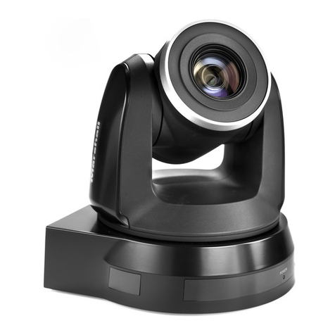
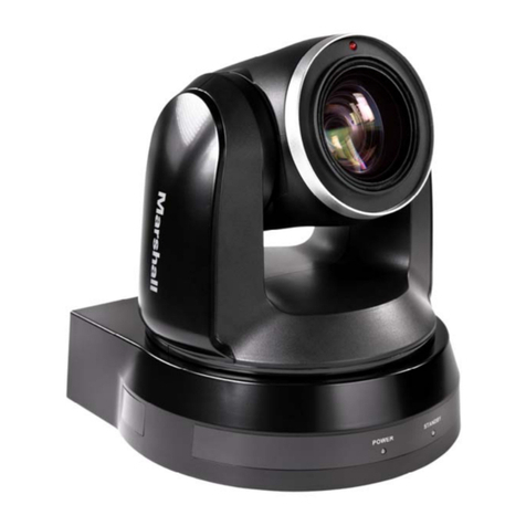
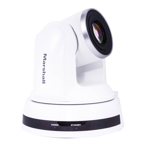
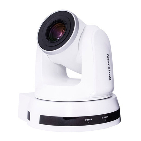
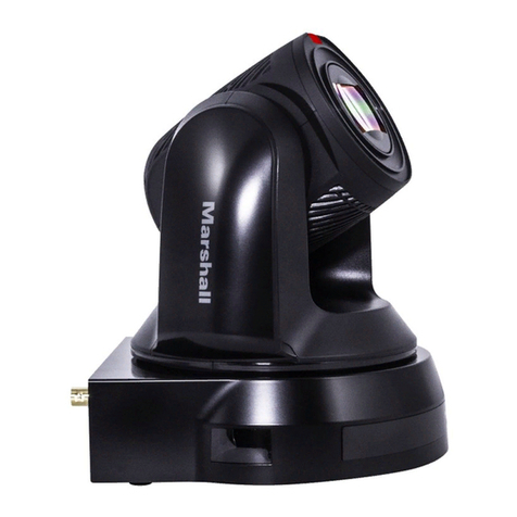
Marshall Electronics CV610-U3-V2 User manual

Broadcast A/V Division
CV610-U3-V2
HD PTZ USB Camera
User Manual

1
Table of Contents
2. What’s In The Box
3. Features
4. Camera Diagrams
5. System Configuration
6. Bottom Dip Switch Settings
7. Adjusting And Setting with Menus
8. Operation Using The Infrared Remote Controller
9. Menu Confirguration
10. Troubleshooting
11. Dimensions
1. Important Information
4.1 C a m e r a
5.1 Connection
7.1 Exposure Menu
8.1 Pan / Tilt / Zoom Operation
4.2 Remote Controller
5.2 Obtain Video Signal
7.2 White Balance Menu
8.2 Operating Multiple Cameras With The Infrared Remote Controller
4.3 Extension Module
5.3 Obtain Audio Signal
7.3 Picture Menu
8.3 Adjusting The Camera
5.4 Camera Control Methods and System Configurations
7.4 Pan / Tilt / Zoom Menu
8.4 Storing The Camera Settings In Memory - The Presetting Feature
7.5 System Menu
04
05
06
09
20
22
29
34
35
36
02
06
09
24
29
07
10
25
31
08
13
26
31
13
27
32
28

CV610-U3-V2 Manual
www.marshall-usa.com 2
Legal notice
The contents of this document are subject to change without prior notice. Updates will be added
to the new version of this manual. We will readily improve or update the products or procedures
described in the manual.
Best effort has been made to verify the integrity and correctness of the contents in this document,
but no statement, information, or recommendation in this manual shall constitute formal guarantee
of any kind, expressed or implied. We shall not be held responsible for any technical or typographical
errors in this manual.
The product appearance shown in this manual is for reference only and may be different from the
actual appearance of your device.
This manual is a guide for multiple product models and so it is not intended for any specific product.
Due to uncertainties such as physical environment, discrepancy may exist between the actual
values and reference values provided in this manual.
Use of this document and the subsequent results shall be entirely on the user’s own responsibility.
WARNING!
Installation and removal of the unit and its accessories must be carried out by qualified personnel.
You must read all of the Safety Instructions supplied with your equipment before installation and
operation.
Safety Information
1. Important Information
Warnings
• If the product does not work properly, please contact your dealer. Never attempt to disassemble
the camera yourself. (We will not assume any responsibility for problems caused by unauthorized
repair or maintenance.)
• This installation should be made by a qualified service person and should conform to all the
local codes.
• When shipping, the camera should be packed in its original packaging.
• Make sure the power supply voltage is correct before using the camera.
• Do not drop the camera or subject it to physical shock.
• Do not touch sensor modules with fingers. If cleaning is necessary, use a clean cloth with a bit
of ethanol and wipe it gently. If the camera will not be used for an extended period of time, put
on the lens cap to protect the sensor from dirt.
• Do not aim the camera lens at the strong light such as sun or incandescent lamp. The strong
light can cause fatal damage to the camera.
WARNING!

3
Maintenance Precautions
• If there is dust on the front glass surface, remove the dust gently using an oil-free brush or a
rubber dust blowing ball.
• If there is grease or a dust stain on the front glass surface, clean the glass surface gently from
the center outward using anti-static gloves or an oil-free cloth. If the grease or the stain still
cannot be removed, use anti-static gloves or an oil-free cloth dipped with detergent and clean
the glass surface gently until it is removed.
• Do not use organic solvents, such as benzene or ethanol when cleaning the front glass surface.
Regulatory Compliance
FCC Part 15
This equipment has been tested and found to comply with the limits for digital device, pursuant
to part 15 of the FCC Rules. These limits are designed to provide reasonable protection against
harmful interference when the equipment is operated in a commercial environment. This equipment
generates, uses, and can radiate radio frequency energy and, if not installed and used in accordance
with the instruction manual, may cause harmful interference to radio communications. Operation of
this equipment in a residential area is likely to cause harmful interference in which case the user will
be required to correct the interference at his own expense.
This product complies with Part 15 of the FCC Rules. Operation is subject to the following two
conditions:
This device may not cause harmful interference.
This device must accept any interference received, including interference that may cause undesired
operation.
LVD/EMC Directive
This product complies with the European Low Voltage Directive 2006/95/EC and
EMC Directive 2004/108/EC.
WEEE Directive–2002/96/EC
The product this manual refers to is covered by the Waste Electrical & Electronic
Equipment (WEEE) Directive and must be disposed of in a responsible manner.

CV610-U3-V2 Manual
www.marshall-usa.com 4
2. What’s In The Box

5
3. Features
• HD resolution allows for high- definition resolution with superior picture quality.
• 10X optical zoom combined with 12X digital zoom, allows to zoom up to 120X totally.
• 62.5 - degrees horizontal angle zoom lens.
• USB2.0 and USB3.0 compatibility.
• Microphone is built in the camera.
• By adopting its wide and dynamic range functions (WDR availability varies with different models),
camera optimizes shooting image that captures bright and dark subjects at the same time.
• It supports protocols: UVC1.5 (Video & Control), UAC2.0, VISCA, PELCO P/D.
• You can use extension module to have the following functions: RS-232 control, RS-422/485
control, HDMI video output, CVBS video output(Inactive), external audio input.
• Adopts the industry standard RS-232 interface of VISCA camera protocol.
• High-speed and low-noise pan/tilt functions support a variety of purposes.
• You can use the infrared remote controller to set the camera and also to select panning, tilting
and zooming from the setting menu.
• You can store up to 6 presets of camera direction and camera parameters into the camera. (Up
to 6 presets on remote controller or 128 presets via protocol programming.)
• The camera supports various HD video formats and has a USB3.0 or USB2.0 video output
terminal.

CV610-U3-V2 Manual
www.marshall-usa.com 6
4. Camera Diagrams
1. 12V DC Power Port
Connect the supplied AC power adaptor and cord.
2. Extension Module Port
Composite port for extra features to provide RS-232, RS-422/RS-485, CVBS, HDMI, Audio Line
functionalities
3. USB 3.0 and USB2.0 Port
Outputs the images from this unit as a USB3.0 and USB2.0 video signal.
Do not apply the voltage higher than the rated value to the USB terminal.
This unit does not have the Battery Charging function. This unit supports USB2.0 and USB3.1.
This unit does not support the USB suspend.
4. IR Remote Controller Sensors
These are sensors to receive commands from infrared remote controller.
5. Power LED Indicator
Turns green when the camera is connected to power outlet. When the power is turned on, it
takes about 15 to 30 seconds to display the image after LED turns on.
6. Lens
This is a 10X magnification optical zoom lens.
7. Communication LED Indicator
Flashes orange when the camera receives commands from the infrared remote controller.
8. MIC
Built-in microphone. Range of sensitivity is within 15 feet.
9. Bottom DIP Switch
Used for setting the camera configuration.
For details, refer to the Bottom DIP Switch Se¬ttings (page 18).
10.Fix mounting holes
11.Tripod mounting holes
4.1 Camera

7
1. Power
• Power ON/OFF the camera.
• When the camera is powered OFF, the camera
turns to the back and would be on standby mode.
• When the camera is powered ON, the camera
turns to the front.
• Powering the camera ON/OFF would not restart
the camera.
2. Camera ID (Total 3) Selector
3. Preset Position (Total 6) Calling and Setting
4. PAN-TILT
• Pan and Tilt direction control
• HOME: Home position, Resolution reset
5. L/R Direction Set
• Left and right orientation setting
6. ZOOM/FOCUS
• Far
• Near
7. Auto/Manual Focus
8. Back Light
9. Video Format Switching
• You can change the video format by keep pressing
the button. (When video format is changed, the
camera would restart and the screen turns black
for few seconds.)
10. MENU
• On screen menu display ON/OFF
11. Audio Switch
• You can turn the Mic built in the camera Off/ON by pressing the button once.
12. Fast/Slow Zooming Speed Switching
13. White Balance
• Change the White Balance setting by pressing the button.
14. De-Flicker
• When you find the video flicking, press the button once to eliminate the flickers.
4.2 Remote Controller

CV610-U3-V2 Manual
www.marshall-usa.com 8
1. Extension Port (Connect to the camera body)
2. Audio line in (3.5mm jack)
3. RS232 Port
4. CVBS (Inactive)
5. RS422/485 Port
6. HDMI Video Output Port
4.3 Extension Module
1
3
2
5
4
6
1. Extension Port (Connect to the camera body)
2. Audio line in (3.5mm jack)
3. RS232 Port
4. CVBS (Inactive)
5. RS422/485 Port
6. HDMI Video Output Port

9
5. System Configuration
5.1 Connection
When the camera is connected to a computer and joystick keyboard via Extension Module with a
VISCA cable (cross type, RS-232), you can operate the camera with the computer and the joystick
keyboard.
When the camera is connected to a joystick keyboard via Extension Module with a control cable
(cross type, RS-422/485), you can operate the camera’s pan, tilt, zoom with the joystick keyboard.
In this connection configuration, Extension Module, DVI-HDMI converter, DVI cable, HDMI cable,
Analog video cable, data cable is required. To obtain these third-party components or accessories,
consult the dealer where you bought your camera.
Notes
• Use only the AC power adaptor (JEITA type4) supplied with the unit. Do not use any other AC
power adaptor.
• Polarity of the plug
• You have to set the video format of the signal to output from the camera. For detailed information
on how to set the video format, see “SYSTEM SELECT switch” on page 19, 23.

CV610-U3-V2 Manual
www.marshall-usa.com 10
5.2 Obtain Video Signal
System Requirements for your PC
1. Operating System: Microsoft Windows 10/Windows 8/Windows 7, Linux Ubuntu 16.04LTS,
macOS Sierra, Microsoft Windows 7 (32-bit) or above is recommended.
2. CPU: 2.0 GHz or higher, dual-core. Intel i3 CPU or higher are recommended.
3. Memory: At least 1 GB. 2 GB (or higher) is recommended.
4. Graphic Card: At least 128 MB display memory. Mainstream discrete graphics with more
than 1 GB display memory are recommended. Make sure that the latest driver is installed on
graphic card.
5. Sound Card: The intercom and voice broadcast require the latest driver on sound card.
6. Network Card: Gigabit Ethernet network cards (or higher) are recommended.
USB3.0 and USB2.0 Video Signal
1. Install video client software on the computer that you want to use the camera on.
2. Use the USB3.0 cable to connect the camera to the computer. Connect the power adapter
to the camera and the power outlet.
3. Power on the camera, wait for a while, the camera will be recognized and installed automatically
by the computer. USB3.0 and USB2.0 drivers are not required for the camera.
4. Open the video client software (Here, we use VLC Media Player for example), under “Media”,
select “Capture Device”. Under Video device name, “MEI CV610-U3-V2” will be listed. Under
the Audio device name, “Digital Audio Interface (MEI CV610-U3-V2)” will be listed. Select
both devices to use.
5. Check the box “show more options”, Select Caching to 500ms.
6. Interface of the setting page and terminology of the setting items may vary according to the
video client software you are using.
7. Click “Play” or “Apply” the selections and the video will be displayed on the screen.

11
The camera is compatible with PC USB2.0 and USB3.0 ports. The camera USB port will output at
the lower resolution while connecting PC USB2.0 port. The following tables are lists of all available
output formats for USB2.0 and USB3.0.
When the camera setting HDMI video format at 1080P60/1080P30/720P60, USB2.0 and USB3.0
resolution with frame rate are available as following list.
HDMI FORMAT USB2.0
Resolution
1920x1080 10P
25P/15P
60P/30P/15P
60P/30P/15P1080P60/1080P30/720P60 30P/15P
1920x1080
1280x720 1280x720
1024x768 1024x768
960x540 960x540
850x480 850x480
800x600 800x600
768x448 768x448
720x576 720x576
720x540 720x540
720x480 720x480
720x404 720x404
640x480 640x480
640x360 640x360
352x288 352x288
USB3.0
Resolution
Frame Rate Frame Rate

CV610-U3-V2 Manual
www.marshall-usa.com 12
When the camera setting HDMI video format at 1080P50/1080P25/750P50, USB2.0 and USB3.0
resolution with frame rate are available as following list.
HDMI / DVI Video Signal
The camera can simultaneously stream HDMI video output with USB3.0 video output. The DVI port
on the rear panel is not for DVI video output but it is a composite port for multiple use. In order to
use HDMI video output, you need to use the Extension Module.
1. Connect the Extension Module to the camera composite port when the power is off. Turn on the
camera power, after the camera initializes, HDMI video signal can be activated automatically.
2. Connect HDMI cable in between the Extension Module and your HDMI display.
3. You now have HDMI video output.
4. You can use HDMI to DVI converter to obtain DVI video signal.
HDMI FORMAT USB2.0
Resolution
1920x1080 10P
50P/25P/10P
50P/25P/10P1080P50/1080P25/720P50 25P/10P
1920x1080
1280x720 1280x720
1024x768 1024x768
960x540 960x540
850x480 850x480
800x600 800x600
768x448 768x448
720x576 720x576
720x540 720x540
720x480 720x480
720x404 720x404
640x480 640x480
640x360 640x360
352x288 352x288
USB3.0
Resolution
Frame Rate Frame Rate

13
5.3 Obtain Audio Signal
1. The camera has built in Mic. It generates audio signal to
the video client software. In the software Audio section
find Microphone setting. “Digital Audio Interface (MEI
CV610-U3-V2)” will be listed. Once you select it as
software audio device, you can use the built-in Mic for
communicating.
2. You can have external audio input by using Extension
Module (optional). The built-in Mic will be deactivated
after the external audio input is used.
5.4 Camera Control Methods and System Configurations
This unit has multiple ways of controlling the USB3.0 camera and various system configuration
capabilities using optional products. This section describes ways of controlling and typical system
examples with the required components and usage of each system.
1. Use the Infrared Remote Controller
2. Use Third party video conference software (UVC1.5 compliant).
3. Use RS-232 (VISCA), via Extension Module (optional).
4. Use RS-422(VISCA)/485 (PELCO P/D) via Extension Module (optional).
Use the Infrared Remote Controller
To operate the camera from a short distance.
System Configuration A
For IR remote control details, refer to Operation Using the Infrared Remote Controller, see page 24.

CV610-U3-V2 Manual
www.marshall-usa.com 14
Use Third party video conference software (UVC1.5 compliant).
The camera can be controlled by any third party UVC1.5 compatible video software. Use USB3.0
cable to connect the camera to the PC/device equipped with UVC1.5 compatible software, the
camera will be recognized automatically. Follow the instruction of the video software you are using.
You can control the camera via PC, Pad, Smartphone.
1. Install video client software on the computer that you want to use the camera on.
2. Use the USB3.0 cable to connect the camera to the computer. Connect the power adapter to
the camera and the power outlet.
3. Power on the camera, wait for a while, the camera will be recognized and installed automatically
by the computer. USB3.0 driver is not required for the camera.
4. Open the video client software (Here, we use ZOOM ROOM for example), on left bottom
under “Stop Video” setting, select video device from Camera list “MEI CV610-U3-V2”.
5. On left bottom under “Mute” Audio setting, select video device from Microphone list “Digital
Audio Interface (MEI CV610-U3-V2)”.
6. Interface of the setting page and terminology
of the setting items may vary according to
the video client software you are using.
7. You can have the video displayed after you
made above selection. Right Click mouse to
pull out action selection, to Request Camera
Control from the meeting group.
8. After you get approve from the meeting
group, the control intereface will pop up. You
can control the camera.
9. For camera control detail, please refer to
video software user guide.

15
Use RS-232 (VISCA), RS-422(VISCA)/485 (PELCO P/D) Control via Extension Module.
The Extension Module is required when using RS-232 / RS-422/485 signals with external control
devices.
You can use RS-232 port or RS-422/485 port on Extension Module to connect to optional controllers,
such as joystick control keyboard, control PC station, to operate the camera.
To perform pan/tilt and zoom operations using the joystick of the control keyboard, and to perform
the Preset operation using the control buttons.
An application software that supports this unit is needed if you use PC station.
System Configuration B

CV610-U3-V2 Manual
www.marshall-usa.com 16
RS232 Connection
1. Set Bottom Dip Switch SW1-B6 to OFF. (See page 18).
2. Set Baud Rate on Bottom Dip Switch to the same as Baud Rate setting on the keyboard you
are using.
(See page 18).
3. Reboot the camera by turning it Off/On after the Bottom Dip Switch has been set up correctly.
4. Camera ID address setting (see page 18).
5. The controller must be VISCA compatible.
6. Camera does not support Daisy Chain in RS232 control mode.
7. You can make RS232 connection cable if you have the following applications:

17
Use RS-422(VISCA) / RS485 (PELCO P/D)
You can use RS-422/485 port connect to optional controllers, such as joystick control keyboard,
control PC station, to operate the camera.
To perform pan/tilt and zoom operations using the joystick of the control keyboard, and to perform
the Preset operation using the control buttons.
An application software that supports this unit is needed if you use PC station.
RS422/482 Connection
RS422 (VISCA) connection
1. Set Bottom DIP Switch SW1-B6 to OFF. (See page 18).
2. Set Baud Rate on Bottom Dip Switch to the same as Baud Rate setting on the keyboard you
are using.
(See page 18).
3. Reboot the camera by turning it Off/On after the Bottom Dip Switch has been set up correctly.
4. Does not need setting camera address in way of RS422(VISCA) controlling.
5. The controller must be VISCA compatible.
6. Camera supports Daisy Chain connection up to 7 cameras.
7. The connection of SONY keyboard is different than other VISCA (None-Sony) keyboard.
SONY Keyboard RS422 Connection

CV610-U3-V2 Manual
www.marshall-usa.com 18
PELCO P/D Keyboard RS485 Connection
1. Use PELCO P/D compatible keyboard.
2. Use preset 95# on the keyboard to bring up/exit camera OSD menu.
3. Use joystick and Button “OPEN” or “CLOSE” to navigate OSD menu.
4. To operate keyboard, please refer to the user manual of the keyboard you are using.
For RS-232 VISCA control, this unit does not support daisy chain connection for using multiple
cameras.
For control details, please refer to Operating Instructions of control keyboard/station software.
• You need to match the communication speed between the camera and the joystick controller.
• You can use the RS-232 connections when using the RS422/485 connection.
• The specified frame rate may change when communicating via a USB3.0 hub.
Marshall Keyboard RS422 Connection
Note

19
Operating Multiple Cameras Using RS-422/485
• Using RS-422 (VISCA), you can connect up to 7 cameras.
• Using RS-485 (PELCO), you can connect up to 255 cameras.
• Using RS-485 (PELCO), all camera addresses must be set up before the connection. You can
set the camera address by operating OSD menu.
• In this case, you can use multiple control keyboards. Only one keyboard that the camera can
response to at one time.
• The joystick of the remote keyboard controller allows comfortable pan/tilt and zoom operations.
System Configuration C (Operating Multiple Cameras)
• You can use the RS-232 connections when using the RS-422/485 connection.
• Only one camera at a time can be displayed on the computer.
• The specified frame rate may change when communicating via a USB3.0 hub
Notes
This manual suits for next models
2
Table of contents
Other Marshall Electronics Security Camera manuals

Marshall Electronics
Marshall Electronics CV630-IP User manual

Marshall Electronics
Marshall Electronics VS-WM202-HDSDI User manual

Marshall Electronics
Marshall Electronics VS-570-HDSDI User manual

Marshall Electronics
Marshall Electronics CV610-U2 User manual

Marshall Electronics
Marshall Electronics CV612HT-4K User manual

Marshall Electronics
Marshall Electronics V-C210-HDSDI User manual

Marshall Electronics
Marshall Electronics CV502-WPM User manual

Marshall Electronics
Marshall Electronics CV620-WH User manual

Marshall Electronics
Marshall Electronics CV620-BK User manual

Marshall Electronics
Marshall Electronics VS-5326-3GSDI User manual