Marshall Electronics CV620-BK User manual

Marshall Electronics
CV620-WH & CV620-BK
Full HD Broadcast PTZ Camera
Installation Guide
Ver.3

Marshall Electronics 1
Table of Contents
Safety Instructions ............................................................................................ 3
Precautions .................................................................................................. 4
FCC Warning................................................................................................ 4
EN55032 (CE Radiation) Warning ............................................................... 4
Package Contents ............................................................................................. 5
Product Overview.............................................................................................. 6
3.1 Overview............................................................................................. 6
3.2 Description of LED indicator............................................................... 6
Instruction for installation ................................................................................ 7
4.1 Preparation before installation............................................................ 7
4.2 Instruction for installation.................................................................... 7
4.3 Connecting the device...................................................................... 16
Remote Control and Setting Menu ................................................................ 19
5.1 Functions of remote control.............................................................. 19
5.2 Setting menu .................................................................................... 20
Descriptions of Major Functions ................................................................... 28
6.1 I would like to switch to CV620......................................................... 28
6.2 I would like to save the current lens position data............................ 28
6.3 I would like to clear the saved position data..................................... 28
6.4 I would like to turn on the back light compensation function............ 28
6.5 I would like to adjust the shooting angle of the lens......................... 28
6.6 I would like to zoom in/out images ................................................... 28
6.7 I would like to adjust the focal length ............................................... 29
6.8 I would like to adjust the focus speed .............................................. 29

Marshall Electronics 2
6.9 I would like to set the image mode................................................... 30
6.10 I would like to freeze images ............................................................ 30
6.11 I would like to rotate the image......................................................... 30
6.12 I would like to change the camera direction ..................................... 30
6.13 I would like to display the current status .......................................... 30
DIP Switch Setting........................................................................................... 31
7.1 DIP SWITCH .................................................................................... 31
7.2 RS-422 Connection .......................................................................... 33
Troubleshooting .............................................................................................. 35

Marshall Electronics 3
Safety Instructions
Always follow these safety instructions when setting up and using the Camera:
1. Use attachments only as recommended.
2. Use the type of power source indicated on the Camera. If you are not sure of
the type of power available, consult your distributor or local electricity
company for advice.
3. Always take the following precautions when handling the plug. Failure to do
so may result in sparks or fire.
Ensure the plug is free of dust before inserting it into a socket.
Ensure that the plug is inserted into the socket securely.
4. Do not overload wall sockets, extensions leads or multi-way plug boards as
this may cause fire or electric shock.
5. Do not place the Camera where the cord can be stepped on as this may
result in fraying or damage to the lead or the plug.
6. Do not block the slots and openings in the case of Camera. They provide
ventilation and prevent the Camera from overheating.Do not place the
Camera on the soft surface of sofas, carpets or others.
7. Never push objects of any kind through cabinet slots. Never allow liquid of
any kind to spill into the Camera.
8. Except as specifically instructed in this User Manual, do not attempt to
operate this product by yourself. Opening or removing covers may expose
you to dangerous voltages and other hazards. Refer all servicing to licensed
service personnel.
9. Unplug the Camera during thunderstorms or if it is not going to be used for
an extended period. Do not place the Camera or remote control on top of
vibrating equipment or heated objects such as a car, etc.
10. Unplug the Camera from the wall outlet and refer servicing to licensed
service personnel when the following situations happen:
If the power cable or plug becomes damaged or frayed.
If the camera is wet with liquid, rain or water.
* Note
Using an incorrect battery type in the remote control may result in breakdown.
Follow local instructions on how to dispose of used batteries.

Marshall Electronics 4
Precautions
Warning: To reduce the risk of fire or electric shock, do not expose this
appliance to rain or moisture.
If Camera will not be used for an extended time, unplug it from the power socket.
Caution: To reduce the risk of electric shock, do not remove cover (or back). No
user-serviceable parts inside. Refer servicing to licensed service personnel.
This symbol indicates that
this equipment may contain
dangerous voltage which
could cause electric shock.
This symbol indicates that
there are important operating
and maintenance
instructions in this User
Manual with this unit.
FCC Warning
This Camera has been tested and found to comply with the limits for a Class A
digital device, pursuant to Article 15-J of FCC Rules. These limits are designed to
provide reasonable protection against harmful interference in a commercial
installation.
This digital apparatus does not exceed the Class A limits for radio noise emissions
from digital apparatus as set out in the interference-causing equipment standard
entitled "Digital Apparatus," ICES-003 of Industry Canada.
Cet appareil numerique respecte les limites de bruits radioelectriques applicables
aux appareils numeriques de Classe A prescrites dans la norme sur le material
brouilleur: "Appareils Numeriques," NMB-003 edictee par l'Industrie.
EN55032 (CE Radiation) Warning
Operation of this equipment in a residential environment could cause radio
interference.
Note
Risk of Electric Shock
DO NOT OPEN

Marshall Electronics 5
Package Contents
CV620 Instruction for
installation Remote Control
Power Cord Power Adapter RS-422 Connector
Appearance may vary
depending on
country/region
Metal Plate A Metal Plate B M3 Screws

Marshall Electronics 6
Product Overview
3.1 Overview
1. Camera lens 2. Power LED indicator
3. Standby LED indicator 4. DVI output
5. Component output 6. Power input
7. IR SELECT 8. OUTPUT Switch
9. Camera Address Selectors 10. RS-232 output
11. RS-232 input 12. RS-422 connection
13. VIDEO output 14. 3G-SDI output
3.2 Description of LED indicator
3.2.1 Power:
3.2.1.1 No light: Power off
3.2.1.2 Green light: In use
3.2.1.3 Flickering green: Signal from the remote control is received;
the indicator flickers every 0.5 second
3.2.2 Standby:
3.2.2.1 Orange: In standby mode
3.2.2.2 No light: Power on
Front View Rear View

Marshall Electronics 7
Instruction for installation
4.1 Preparation before installation
Installation and connection of CV620 Camera requires special skills. To install by
yourself, please follow necessary steps, ensure steady and tight installation of the
device, and pay attention to your safety to avoid any accident.
4.1.1 Ensure the safety of the installation environment. Please do
not install the device on unstable ceiling or in a place where
the device is in danger of falling to avoid any accident.
4.1.2 Please check whether accessories in the box are complete
or not. Please contact the supplier for any shortage, and
make sure to keep the accessories in the box intact.
4.1.3 Please choose a proper place for installation of CV620 in
advance. Please determine an installation place according
to the following requirements:
4.1.3.1 Confirm the position for the object to be captured.
4.1.3.2 Confirm whether the CV620 is set at a proper distance from other
light sources.
4.2 Instruction for installation
4.2.1 I would like to install CV620 on the desk
4.2.1.1 Precautions for installation
Please install the machine on a flat desk
Do not grab the camera head by hand when handling the device
Do not rotate the camera head by hand. Improper rotation may
result in breakdown of the camera

Marshall Electronics 8
4.2.1.2 Installation steps
1. Please adjust DIP switch at first prior to installation.
* Please refer to Chapter 7 DIP Switch Setting for the relevant
descriptions on DIP switch.
2. Place the camera on a flat desk directly to ensure the normal
vertical and horizontal operation of the machine.
4.2.2 I would like to install CV620 on the ceiling
4.2.2.1 Prepare for the parts and equipment required during the
installation
1. Accessories of CV620 in the box (metal plates A, B and M3
screw x 7)
2. Screw for locking on ceiling mounted hanger x 4
3. Drilling machine, screw driver, ladder
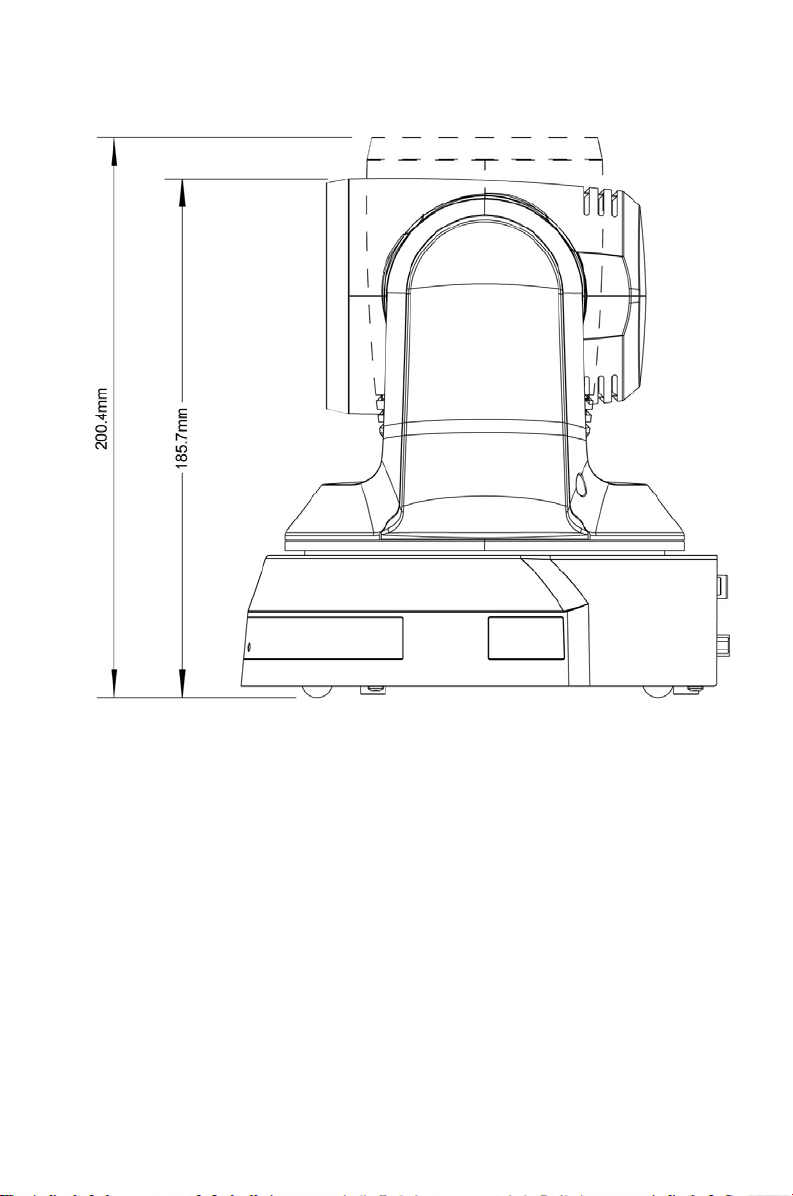
4.2.2.2 Dimension
Length x Width x Height: 174x186.13x185.88. Weight: 2.0Kg
Marshall Electronics 9
4.2.2.3 Max. rotation dimension of camera
This manual suits for next models
3
Table of contents
Other Marshall Electronics Security Camera manuals

Marshall Electronics
Marshall Electronics CV610-U3-V2 User manual

Marshall Electronics
Marshall Electronics CV610-U2 User manual

Marshall Electronics
Marshall Electronics CV-340-CS User manual

Marshall Electronics
Marshall Electronics VS-570-HDSDI User manual

Marshall Electronics
Marshall Electronics VS-5326-3GSDI User manual

Marshall Electronics
Marshall Electronics CV200-MB User manual

Marshall Electronics
Marshall Electronics CV620-BK2 User manual

Marshall Electronics
Marshall Electronics CV502-WPM User manual

Marshall Electronics
Marshall Electronics CV620-WH User manual

Marshall Electronics
Marshall Electronics CV630-IP User manual


