Marshall Electronics VS-101-HDSDI User manual

User Manual Ver. 1.0.2
Marshall Electronics
VS-101-HDSDI
H.264 HD Video Server

This page intentionally left blank.

3IP Server Instruction Manual
Table of Contents ..................................................................................................................... 3
Introduction .............................................................................................................................. 5
About User Manual ......................................................................................................... 5
Feature ............................................................................................................................ 5
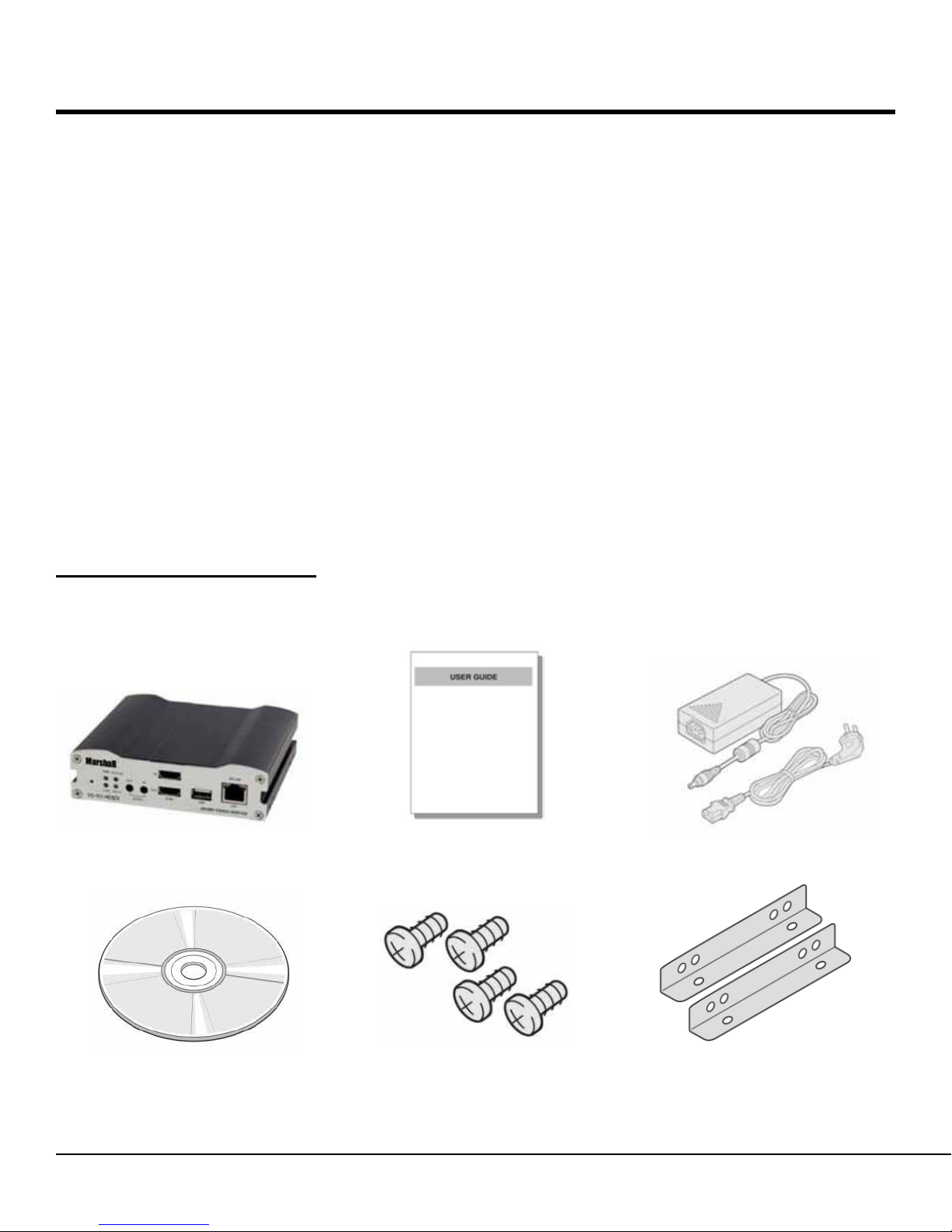
Product and Accessories ................................................................................................. 6
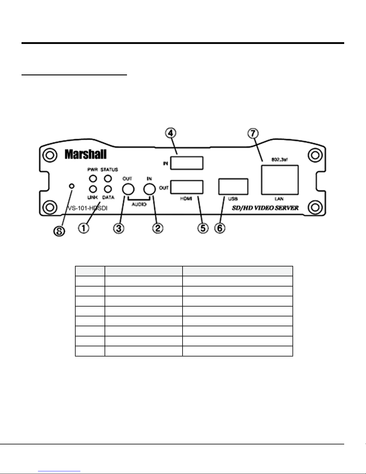
Part Names and Functions .............................................................................................. 7
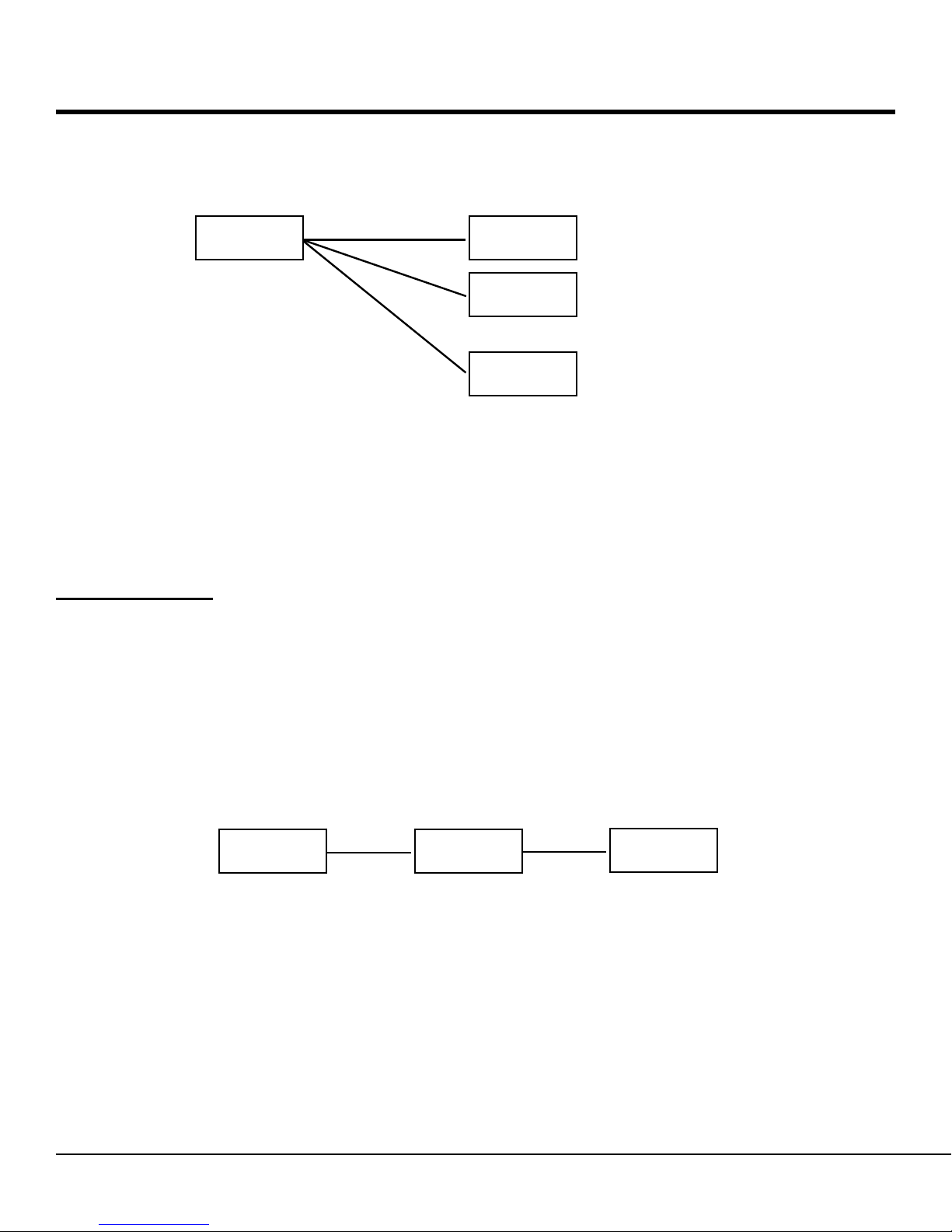
System Modes and Connections .................................................................................... 9
Installation ................................................................................................................................ 12
Connecting Video ............................................................................................................ 12
Connecting Audio ............................................................................................................ 12
Connecting Serial Ports .................................................................................................. 12
Connecting Sensor and Alarm ........................................................................................ 12
Connecting Power ........................................................................................................... 13
Check if It Works ............................................................................................................. 13
System Operation .................................................................................................................... 14
LED Display .................................................................................................................... 14
Remote Video Monitoring ................................................................................................ 15
Initialization of IP Address ............................................................................................... 17
Remote Conguration ............................................................................................................. 18
Encoder Conguration ............................................................................................................ 19
SystemConguration...................................................................................................... 19
VideoConguration......................................................................................................... 22
AudioConguration......................................................................................................... 26
NetworkConguration..................................................................................................... 27
SerialPortConguration................................................................................................. 31
EventConguration......................................................................................................... 33
PresetConguration....................................................................................................... 36
RecordConguration...................................................................................................... 37
UserConguration........................................................................................................... 46
Decoder Conguration ............................................................................................................ 49
SystemConguration...................................................................................................... 49
VideoConguration......................................................................................................... 50
NetworkConguration...................................................................................................... 51
Table of Contents

4IP Server Instruction Manual
True Manager ............................................................................................................................ 53
True Manager Software ................................................................................................... 53
Server Registration and Removal ................................................................................... 53
Server Connection Management...................................................................................... 56
Server Status Monitoring ................................................................................................. 57
Network and System Diagnostics..................................................................................... 58
F/W Upgrade.................................................................................................................... 61
RemoveCongurationandVideoMonitoring................................................................... 61
Trouble Shooting ...................................................................................................................... 62
Appendix ................................................................................................................................... 63
Appendix A: Sensor Port & Alarm Port ............................................................................ 63
Appendix B: Serial Port ................................................................................................... 65
Table of Contents
■Make sure to turn off the power before installing VS-101-HDSDI.
■Do not install in locations with direct sunlight or in dusty areas.
■Make sure to use the product within the temperature and humidity specications.
■Do not operate the product in locations with strong vibrations or magnetic elds.
■Do not insert electrically conductive materials in the ventilation hole.
■Do not open the product. There are no user serviceable parts inside.
■To prevent from overheating, make sure to keep a clearance of at least 4 inches from the
ventilation hole.
■Make sure the voltage is correct (220V/110V) before connecting the power.
WeappreciateyourpurchaseoftheVS-101-HDSDI.
Before installing the product, please read the following with care.
Safety Precaution

5IP Server Instruction Manual
About This Manual
ThisUserManualprovidesinformationonoperatingandmanagingtheVS-101-HDSDI.TheManual
includesinstructionsfortheinstallation,operationandcongurationoftheVS-101-HDSDIaswellas
troubleshooting tips.
Features
VS-101-HDSDIisaVideoandAudiotransmissionsystemthatprovidesHDVideoandAACaudio
along with remote functions using IP protocol through existing LAN, ADSL/VDSL, and Wireless LAN
networks.WhenencodingtheVS-101-HDSDIcompressesvideoandaudiodataandtransmitsit.
WhenDecodingtheVS-101-HDSDIreceivesthedataanddecompressesit.
■Video
State-of- the art H.264 & MJPEG Compression Algorithm.
Compression and Decompression with 18 Resolution formats.
: Full HD (1920x1080) ~ CIF(352x240)
Wide Range of Video Transmission Rate : 32kbps ~ 8Mbps
Various Transmission Mode : CBR, VBR
Motion Detection
HDMI In/Output
HD-SDI In/Output
■Audio
Multi-Transmission Mode : Unidirectional or Bidirectional stereo audio
■Network
Static IP & Dynamic IP (DHCP) Support
One to One Connection & One to Multiple Connection
Multi-Casting
Various Protocols support : TCP/IP, UDP, Multicast, DHCP, SMTP, HTTP, SNMP, RTP,
RTSP
■Serial Data
Two serial ports : RS-232, RS-422/485
Various PTZ camera protocols
Data pass-through mode : Serial data communication between Encoder - Decoder
Introduction

6IP Server Instruction Manual
■Sensor and Alarm
Connections to external sensor and alarm devices
Event Alarm
■USB
Connection to an external USB storage for remote access, recording and playback
■User Interface
Display system status with OSD (On Screen Display)
Conguration and upgrade using dedicated program (True Manager)
System conguration using Internet Explorer
■Reliability
Reliable embedded operating system
Auto reboot and system recovery after power loss
Product and Accessories
Brackets
VS-101-HDSDI User Manual Power adapter and Cable
Software CD Screws
Introduction

7IP Server Instruction Manual
Part Names and Functions
■Front View
Introduction
No. Parts Function
1 LED Display system status
2 Audio Input Audio Input
3 Audio Output Audio Output
4 HDMI Input HDMI Video Input
5 HDMI Output HDMI Video Output
6 USB Port USB2.0
7 LAN 100/10-base-TEthernet
8 Reset Button Initialization of network setting

8IP Server Instruction Manual
■Rear View
Introduction
No. Parts Function
1 Power DC +12V power input
2 Sensor Sensor Input
3 Alarm Alarm or Relay Output
4 RS-422/485 Serial port for PTZ control and etc
5 RS-232 Serial port for PTZ control and etc
6 Video Output Composite or HD-SDI Output
7 Switch Composite or HD-SDI Switch
- Switch Down: Composite Video
- Switch Up : HD-SDI Video
8 Video Input Composite or HD-SDI Input

9IP Server Instruction Manual
System Modes and Connections
TheVS-101-HDSDIoperatesasanEncoderorDecoder.TheVS-101-HDSDIcanbeconnectedin
either 1-to-1 fashion where one encoder is connected one decoder or 1-to-many fashion where one
encoder is connected to many decoders.
Following chart shows data status of video, audio and serial data on each mode.
The System Mode is determined by the video communication status, while Audio and Serial Data
modes are always capable of Unidirectional or bidirectional transmission.
■Topology
Generally,theencoderanddecoderareconnectedin1-to-1mode.Tosupportspecicsituations,
1-to-1 multiple connections are also supported.
1:1 Connection (Unidirectional Transmission)
Mostlyusedcongurationis1to1connection.Anencoderisinstalledatasitewherevideoimages
can be transmitted and a decoder is installed at a center location to receive and view the video
images on monitors. Audio and serial data are transferred in either direction.
A decoder and encoder can be connected by setting the encoder’s address at the decoder’s remote
IP.
Introduction
System Mode Video Audio Serial Data
Encoder Transmit Transmit/Receive Transmit/Receive
Decoder Receive Transmit/Receive Transmit/Receive
Remote Center
Encoder Decoder
→
Site

10 IP Server Instruction Manual
■1:N Connection (Unidirectional Transmission)
Inthisconguration,asitecanbemonitoredfrommanyremotecenterlocations.Althoughupto‘n’
decoders can be connected to an encoder, in the real network environment, Maximum connections
would be limited by network bandwidth connection
Functionally, the CMS (Central Monitoring System) software can replace the decoder.
Multicast Mode
In the network supporting multicast mode, if Multicast is setup as a system protocol, you can use
bandwidthefcientlyregardlessofthenumberofdecoders.In1:Nconnection,alargenumber
of decoders can receive audio and video data from an encoder by using a single streaming
transmission.
■Relaying
In this arrangement, video and audio can be retransmitted from a center to another center. The
arrangement is useful when the network bandwidth at the site is limited while there is more than one
center wanting to monitor the site.
Introduction
Encoder Decoder
→
Decoder
Decoder
1
2
n
→
→
IP Server Decoder
→Decoder
→
Remote Center #1Site Remote Center #2

11IP Server Instruction Manual
■CMS(Central Monitoring System)
CMS (Central Monitoring System) is a Windows based remote monitoring program to access multiple
encoders for real-time monitoring or control of the encoders and connected cameras. Please refer to
CMS User Manual for more information on CMS.
Introduction
Encoder Decoder
→CMS
→
Remote CenterSite
Encoder CMS
→
Remote CenterSite

12 IP Server Instruction Manual
Connecting Video
■Encoder System
Connecting the HD Camera
Connect the HDMI or HD-SDI output of the HD camera to the Appropriate HDMI or HD-
SDIInputportofVS-101-HDSDI.ForHD-SDItheinputdipswitchshouldbesettotheUP
position
Connecting a standard resolution NTSC/PAL Camera
ConnectthecameratotheVideoInputportoftheVS-101-HDSDI.ForstandardNTSC/PAL
the video input dip switch should be set to the Down position.
■Decoder System
ConnectamonitortotheHDMIorCOMPOSITE(HD-SDI)OutputoftheVS-101-HDSDI.
Connecting Audio
Audio is bidirectional regardless of the system mode (Encoder or Decoder).
Ifnecessary,itcanbeconguredtobetransmit-only,receive-onlyorbidirectionalmode
■Connect the audio input and output ports to the appropriate audio devices as required.
■The Audio I/O is -10dBu unbalanced line level stereo, appropriate microphone or speaker
amplication is required.
Connecting Serial Ports
Two serial ports are provided for remote camera control and PTZ controller receiver. These are
connected in connected in 1-to-1 fashion and work in a pass-through mode. This means that
commands at a local system’s COM1 port will be transparently passed to the remote system’s COM1
port. Also, a command at a local system COM2 port will pass to the remote system’s COM2 port.
Connecting Sensor and Alarm
Connect sensor and alarm devices to corresponding terminals as required.
Installation

13IP Server Instruction Manual
Connecting Power
Afterconrmingthepowersource,connectpoweradaptorandconnectthe12VDCconnectortothe
VS-101-HDSDI.Thesystemwillbegintobootuptotheoperatingmode.
Check if it Works
Once the power is supplied to the server, it will start booting. The system will boot up to an operating
modeafterapproximately40-60seconds.ThegreenLEDontheEthernetportwillashindicatingthe
system is ready.
Software provided on the disc called True Manager allows you to check the IP address and other
networkdetailsoftheserver.PleaserefertotheTrueManagermanualforinstructionsonhowtond
the IP address of the server and if required changing it.
■Encoder LED Display
Above LED status shows that the server is connected but a decoder is not connected. Once the
encoder is connected to a decoder, color of “LINK” LED will turn into green color and “ DATA” LED will
blink as video and / or audio transmissions occur.
■Decoder LED Display
Above LED status shows that the Decoder has started without connecting to an encoder. Once an
encoder is connected, the color of “LINK” LED will be turned to green and the “DATA” LED will blink
as video and / or audio data transmissions occur.
Installation
PWR STATUS LINK DATA
OFF OFFRed Green
Blinking
PWR STATUS LINK DATA
OFFRed Green
Blinking

14 IP Server Instruction Manual
■Description of LED
System Operation
LED State Description
PWR Off Power off
Red Power on
STATUS Green blinking Normal operation
Red System failure: Needs
diagnostics
Constant change of colors
between Red and Green
NTSC/PAL setting does not
match with input video signal
Red blinking Failed to obtain IP address in
DHCP mode
Constant change of colors
between Green blinking 2
times and Red blinking once
Failed to register on DDNS
server
Green blinking, Red blinks
once every 5 seconds
Video loss in Encoder system
Constant change of colors :
Green, Orange, Red color in
turn
Formatting USB storage
device
LINK Off No connection to remote
system
Green Connected to a remote system
Red blinking Decoder only: trying to
connect to an Encoder
Orange Illegal connection
(unsupported combination of
system modes)
DATA Green Data transmission in progress
Red Data loss
Off No data transmission

15IP Server Instruction Manual
Remote Video Monitoring
There are two ways to view video when the connections are completed between a site and center
system. In order for a proper operation, an IP address must be set accordingly. Please refer to True
Manager in Chapter 3 or Remote Setting in Chapter 4 for further details.
■Video Monitoring with Decoder System
Once the IP address is set in the remote IP address section of the decoder, the decoder system will
connect to the encoder systems and start receiving the video images. A monitor must be connected to
the decoder in order view the video images.
■Video Monitoring using Internet Explorer
OpenInternetExplorerandentertheencoder’sIPaddress.Thesystemwillaskforconrmationto
install Active-X control. Once authorized, the Internet Explorer will start to display video images from
the encoder in the Live View window as shown.
System Operation
Default ID : admin Default Password : 1234
DefaultIPAddress:http://192.168.10.100

16 IP Server Instruction Manual
■Video Selection
TheVS-101-HDSDIiscapableofdualstreaming.VideoSelectionallowsyoutochoose
Primary Video image or Secondary Video image. Video Image is displayed according to the
resolutionsetinvideoconguration.Whendualstreamingisnotactivatedandsecondary
mode is selected, video will not be displayed.
■Screen Size : Adjust screen size
■Digital Zoom
Max 5x Digital Zoom is available
System Operation

17IP Server Instruction Manual
■Focus Near, Focus Far, Auto Focus
Adjust the focus
■Sensor Input
WhenthesensoronVS-101-HDSDIistriggered,thelightturnsred.
■Alarm Output
IndicatesthealarmdeviceconnectedtoVS-101-HDSDIisactive.
■Screen Capture (Snapshot)
CapturepicturesandstoreasBMPorJPEGles.
■Audio Transfer (Talk)
Transfer audio
Initialization of IP Address
IfaVS-101-HDSDIIPaddressislost,theunitcanberesettothefactorydefaultIPaddressusingthe
reset button in the back side of the system.
1. WhiletheVS-101-HDSDIispowered,presstheresetbuttonandholdfor5seconds.
2. The system will reboot automatically
3. OncetheVS-101-HDSDIrebootstheIPaddresswillresettothesystemdefaultas
below.
System Operation
IP mode Fixed IP IP address 192.168.10.100
Subnet mask 255.255.255.0 Gateway 192.168.10.1
Base port 2222 HTTP port 80

18 IP Server Instruction Manual
Remote Conguration
Remotecongurationoftheserverisavailablebywebbrowser.EnterIPaddressoftheVS-101-
HDSDI when the live view screen appears as below, Press the Setup button in the screen to set the
server.
For Remote Setting, the user must be authorized higher than manager level.
Theremotecongurationwindowmaybeslightlydifferentdependingonthesystemmodes(Encoder,
Decoder).ThegeneralexplanationofthecongurationinthismanualisbasedonEncodersystem
anddifferencesaccordingtothemodeswillbeclariedwhenneeded.
Thecongurationsaregroupedinto9categories:System,Video,Audio,Network,Serial,Event,
Preset,RecordandUser.AnycongurationchangesarenotapplieduntilApplybuttonispressed.
Leaving the page without pressing Apply button, any changes in the page will be discarded.
Remote Conguration
Enter IP address
Press setup button

19IP Server Instruction Manual
Encoder Conguration
WhilemostcongurationitemsarecommonforEncoderandDecodermode,thereareitemswhich
arerelevanttospecicsystemmode.AllthecongurationitemsforEncodermodeareexplainedrst.
Then,itemsspeciconlytoDecodermodearedescribed.ThesectionsforDecoderwillnotinclude
items are common to Encoder mode .
System Conguration
Encoder Conguration

20 IP Server Instruction Manual
■General
System Mode
SelectsystemMode:SetstheVS-101-HDSDItobeanEncoderorDecoder.
System ID
SetstheVS-101-HDSDIID(Name).Thenamesetisdisplayedwiththevideoimageinthe
web browser and remote decoder. This is useful to quickly identify feeds from Studio One or
another camera in the facility.
Language
Selectthelanguagetobeusedforweb-basedconguration
■Firmware
Firmware version
Currentrmwareversion
Upgrade
Afterselectingarmwareleinyourcomputer,upgradetheVS-101-HDSDIwiththeselected
rmwarele.
■Time
Start Time
Latest system boot date and time
Current Time
Current date & time: Enter a new date and time and press Set Current Time button to update
date & time
Time Zone
Select time zone of where the system is installed. Depending on the time zone, Daylight
Saving Time is adjusted automatically
Thecurrenttimewillbedisplayedonremotesoftwareandrecordinglesaccordingtothe
selected time zone, not the time set on the remote computer.
.
A time zone is a region of the earth that has uniform standard time, usually referred
to as the local time. By convention, time zones compute their local time as an offset
from UTC (Coordinated Universal Time). In casual use, GMT (Greenwich Mean
Time) can be considered equivalent to UTC. Local time is UTC plus the current time
zone offset for the considered location.
Encoder Conguration
Table of contents
Other Marshall Electronics Server manuals