Marshall Electronics AR-DM1-B User manual

2
Contents
Product Overview..................................................................................................................................................................3
Features .................................................................................................................................................................................3
Installation and Initial Setup ................................................................................................................................................4
Unpacking............................................................................................................................................................................................4
Input / Output Module Installation....................................................................................................................................................4
Audio Monitor Installation..................................................................................................................................................................4
Quick Start Guide..................................................................................................................................................................5
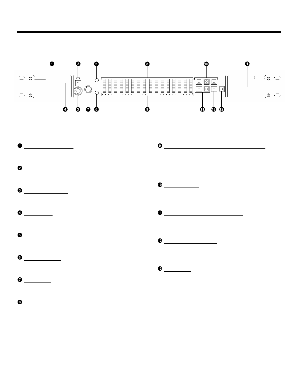
Front Panel Features ............................................................................................................................................................6
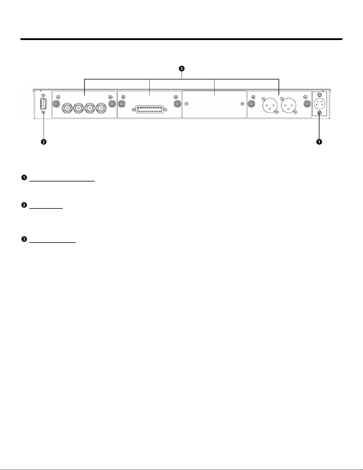
Rear Panel Features..............................................................................................................................................................7
Basic Operation.....................................................................................................................................................................8
Overview..............................................................................................................................................................................................8
Selecting an Input Module.................................................................................................................................................................8
LED Bar Graphs .................................................................................................................................................................................8
Audio Monitoring.................................................................................................................................................................................9
Monitor Modes..................................................................................................................................................................................9
Channel-Assign Indicator LEDs........................................................................................................................................................9
Headphone Output and Audio Adjustments.................................................................................................................................10
Headphone Output..........................................................................................................................................................................10
Volume Control...............................................................................................................................................................................10
Balance Control..............................................................................................................................................................................10
Mute Functions...............................................................................................................................................................................10
Reset Functions..............................................................................................................................................................................10
DOLBY Encoded Signals....................................................................................................................................................11
DOLBY Signal Indication.................................................................................................................................................................11
Decoding and Monitoring DOLBY Signals....................................................................................................................................11
Introduction.....................................................................................................................................................................................11
Entering DOLBY Decoding Mode ...................................................................................................................................................11
Downmixing DOLBY Decoded Audio..............................................................................................................................................11
DOLBY Downmix Configurations...................................................................................................................................................12
Optional Modules................................................................................................................................................................13
Input Modules....................................................................................................................................................................................13
ARDM-AES-BNC............................................................................................................................................................................13
ARDM-AES-XLR.............................................................................................................................................................................13
ARDM-HDSDI.................................................................................................................................................................................13
ARDM-AA-8XLR.............................................................................................................................................................................13
Output Modules ................................................................................................................................................................................14
ARDM-AES-4OUT..........................................................................................................................................................................14
ARDM-AA-2OUT.............................................................................................................................................................................14
DOLBY Module.................................................................................................................................................................................14
ARDM-D552 ...................................................................................................................................................................................14
Module Installation..............................................................................................................................................................15
Input / Output Module Installation..................................................................................................................................................15
DOLBY Module Installation.............................................................................................................................................................16
Specifications......................................................................................................................................................................18
AR-DM1-B Audio Monitor................................................................................................................................................................18
Input / Output Modules ....................................................................................................................................................................19
Warranty...............................................................................................................................................................................20

Product Overview
The AR-DM1-B is a 16-channel digital audio monitoring system featuring 10-segment tri-color LED bar graphs. Designed
for ultra-near field audio monitoring in space critical environments, the AR-DM1-B is ideal for TV facilities, studios, post-
production facilities, VTR bays, mobile production vehicles, satellite links, and wherever multi-channel audio monitoring is
required.
The AR-DM1-B features stereo loudspeakers in a compact 1RU form factor, with Class D Amplification and 100% digital
processing providing pristine audio quality. Interchangeable input and output modules provide unrivaled flexibility – up to
four I/O modules can be installed in a single AR-DM1-B audio monitor, each module with up to 16 channel inputs,
providing a possible 64 channels per audio monitor. Input choices include balanced/unbalanced AES/EBU, SDI video with
embedded audio, and balanced analog audio. With an optional DOLBY®module, the AR-DM1-B supports decoding and
monitoring of DOLBY®Eand DOLBY®DIGITAL (AC-3) signals, with the option to output discrete decoded channels or
pass through encoded bit streams. Flexible monitoring modes include mono, stereo, and various stereo downmix
configurations for multi-channel audio. 10-segment tri-color LED bar graphs allow simultaneous VU/PPM metering of 16
audio channels. Additional features include volume and balance controls, a headphone jack, and an RS-485 port for on-
site firmware upgrades.
Features
■Superior Audio Quality
Stereo Loud Speakers provide superior audio quality in a compact 1RU form factor.
■Sixteen LED Bar Graphs
10-Segment Tri-Color LED Bar Graphs allow simultaneous monitoring of VU/PPM levels for 16 audio channels. Bar
graphs also indicate AES/EBU signal presence.
■Flexible I/O
Modular design allows the AR-DM1-B to be customized with a variety of inputs and outputs, including balanced and
unbalanced AES/EBU, SDI with embedded audio, and balanced analog audio.
■Digital Processing
100% digital signal processing and Class D amplification provide pristine audio signal quality.
■Selectable Stereo Downmix Configurations
Multi-channel audio can be downmixed in a variety of stereo configurations including 5.1, 7.1 and more.
■DOLBY DIGITAL / DOLBY E Decoding
Optional ARDM-D552 module allows decoding of DOLBY E and DOLBY DIGITAL multi-channel audio signals.
Decoded channels can be output via output modules. A variety of downmix presets based on DOLBY metadata are
available, including Lt/Rt, Lo/Ro, etc.
■Firmware Upgradeable
An RS-485 port enables on-site firmware downloads for future upgrades and new features.
®
DOLBY
is a registered trademark of Dolby Laboratories

4
Installation and Initial Setup
Unpacking
Carefully unpack the AR-DM1-B audio monitor and verify that the following items are included:
• AR-DM1-B Audio Monitor*
• Power Supply with 4-Pin XLR Connector
• AC Power Cable
• Operating Instructions
*AR-DM1-B may be pre-configured with input/output modules or DOLBY module if ordered as such. DOLBY module
installation is indicated by a label on the exterior of the unit.
Inspect the unit for any physical damage that may have occurred during shipping. Should there be any damage,
immediately contact Marshall Electronics at (800) 800-6608. If you are not located within the continental United States,
call +1 (310) 333-0606.
Input / Output Module Installation
If your audio monitor has not been pre-configured with input and output modules at the factory, you must install at least
one input module to use the audio monitor. Additional modules can also be purchased and installed when needed. The
modules are designed for simple installation and removal without tools. For detailed instructions, see Module Installation
(page 15).
Note: Modules cannot be installed or “hot swapped” while the audio monitor is powered on. Ensure that the audio monitor
is powered off before installing or removing modules.
Audio Monitor Installation
The AR-DM1-B audio monitor can be installed in an EIA-standard 19-inch rack. At only 7.8” inches deep, the AR-DM1-B
can also be installed in many shallow racks cases. Alternately, the AR-DM1-B audio monitor can be placed on any level
surface. For optimum sound quality, the audio monitor should be installed at ear level.

5
Quick Start Guide
1. Install an Input Module
Ensure at least one input module is installed in the AR-DM1-B audio monitor. If no modules are installed, see
Module Installation (page 15) for detailed instructions.
2. Connect an Audio Source
Connect an audio source to the audio monitor. Depending on the chosen input module, the signal could be SDI
video with embedded audio, AES/EBU digital audio, analog audio, etc. Some modules may require a breakout
cable for the appropriate connections. See module specifications for details.
3. Power On the Audio Monitor
Supply power to the audio monitor by connecting the included power supply to an AC power source (100-240 V @
50/60 Hz) and connecting the power supply’s 4-pin XLR connector to the back of the audio monitor. The Power LED
on the front panel will illuminate green.
4. Select an Input Module
Using the SRC switch on the front panel, choose the module location (1-4) to which the input is connected (Modules
are identified as numbers 1-4, with location no.1 on the far left if facing the rear of the audio monitor). The LED bar
graphs will then immediately show which channels have an audio signal present. You may not hear audio as yet.
5. Choose a Monitor Mode
To hear one audio channel at a time, press the Single button. To hear a stereo pair of channels, press the Pair
button. Use the Left and Right buttons to switch channels or channel pairs. The LEDs under each bar graph will
indicate which channels are selected. To hear channels 9-16, press the 9-16 button.
6. Adjust the Volume and Balance
Use the Volume and Balance controls to adjust the sound level and stereo balance.

6
Front Panel Features
Stereo Loudspeakers
The stereo loudspeakers are active unless
headphones are connected.
Power Indication LED
The power LED will illuminate green when power is
supplied to the audio monitor.
Headphone Output
The headphone output accepts stereo headphones
with a 1/4" TRS connecter. See page 10.
Mute Button
The mute button disables the speakers and
headphone output. See page 10.
Volume Control
The volume control affects both the stereo speakers
and headphone output. See page 10.
Balance Control
The balance control adjusts the relative level of each
channel in the current stereo mix. See page 10.
SRC Switch
The source switch is used to select the module
source from which to monitor audio. See page 8.
LED Bar Graphs
The LED bar graphs display signal presence and
VU/PPM information for 16 channels of audio. See
page 8.
Channel-Assign and DOLBY Indicator LEDs
The channel assign LED below each bar graph
indicates how that channel is being reproduced
through the stereo speakers (see page 9). The
DOLBY LED below each channel pair indicates the
presence of a DOLBY encoded signal (see page 11.)
Monitor Modes
The single, pair, and mix buttons are used to select
the mode in which to monitor audio channels. See
page 9.
Left and Right Navigation Buttons
The left and right buttons are used to select single
channels, channel pairs, or downmix configurations.
See page 9.
DOLBY Decode Button
The DOLBY decode button is used to decode the
DOLBY signal on the selected channel pair (ARDM-
D552 Module required). See page 11.
9-16 Button
The 9-16 button is used to monitor and downmix
channels 9-16 from the selected input module. The
LED on the 9-16 button will illuminate when channels
9-16 are selected. See page 9.

7
Rear Panel Features
Note: AR-DM1-B audio monitor shown with 3 modules: ARDM-AES-BNC, ARDM-AES-XLR, ARDM-AA-8XLR
Power Input Connector
Use only the included power supply to power the AR-DM1-B audio monitor.
RS-485 Port
The RS-485 port is used to download firmware to the AR-DM1-B audio monitor. Contact Marshall Electronics regarding
available firmware upgrades and instructions.
I/O Module Slots
Four slots are available for a variety of I/O modules. See page 13 for available modules.

8
Basic Operation
Overview
Basic operation of the AR-DM1-B Audio Monitor involves selecting an input module as the audio source, using the LED
bar graphs to visually monitor signal levels, and choosing a mode in which to monitor audio through the stereo speakers.
The user can switch between up to four installed I/O modules, each providing up to 16 channels of audio. The LED bar
graphs will then display VU/PPM levels for each audio channel from the selected input module. Finally, audio channels
from the selected module can then be monitored through the stereo speakers in a variety of ways: Any single channel can
be monitored in mono, any channel pair can be monitored in stereo, and any group of eight channels can be down-mixed
to stereo using a variety of configurations.
Selecting an Input Module
The SRC switch is used to select the source module from which to monitor audio.
• Module slots are identified with numbers 1-4, from left to right when facing the rear panel of the audio monitor.
• Only the selected module’s channel inputs can be monitored simultaneously. Audio channels from different input
modules cannot be monitored at the same time. Loop-through outputs and dedicated output modules however will
function at all times regardless of the selected module. See module specifications for details.
• If the SRC switch is set to a module slot where an output module or no module is present, no audio will be visible on
the meters or audible from the speakers.
• Each module location retains exclusive settings – Channel selections and mix configurations are saved separately
for each module (1-4) when switching modules. Settings are only reset once the module is removed from the audio
monitor. Volume,Balance, and Mute settings are common to all modules.
LED Bar Graphs
The LED bar graphs display signal level information for each audio channel.
Once an input module is selected using the SRC switch, the LED bar graphs immediately begin displaying signal level
information for up to 16 channels of audio, depending on the number of channels available from the module. The bar
graph for each channel will function even if that channel is not selected for monitoring through the stereo speakers as
described in the Audio Monitoring section.
The LED bar graphs have the following functions:
VU/PPM Signal Level
Each 10-segment LED bar graph represents the full scale of dynamic range of the audio monitor (-66dBFS to 0dBFS).
Signal level is simultaneously displayed in two ways. Signal level is shown in Volume Units – the average volume of
the signal – reflecting the perceive loudness of the signal. The bar graphs also function as Peak Program Meters,
indicating signal peaks by displaying a single red bar at the peak level with a slow decay time.
Digital Audio Signal Presence
Unlike analog audio signals, digital audio signals contain a constant bit stream even when the audio content is silent.
Such bit stream presence during silence is indicated by red illumination of the first LED segment of the corresponding
channel’s bar graph. This feature is useful in differentiating between an accidentally disconnected cable from silence in
the audio programming. This feature is not available for analog audio inputs.
Note: If a channel pair contains a DOLBY encoded signal, the corresponding LED bar graphs will not show a signal level.
DOLBY signal presence is indicated by the illumination of the blue LED below each channel pair. See the DOLBY
Encoded Signals section on page 13 for more information.

9
Basic Operation (continued)
Audio Monitoring
■Monitor Modes
Audio channels from the selected input module can be monitored through the stereo speakers in three ways: one
channel at a time (mono), two channels at a time (stereo), or as a stereo mix of multiple channels (5.1, 7.1, etc.).
Single Mode
Press the SINGLE button to monitor one channel at a time. The selected channel will be reproduced through both
speakers equally. Use the LEFT and RIGHT buttons to select amongst channels 1-8. Pressing the 9-16 button
will enable the LEFT and RIGHT buttons to select amongst channels 9-16.
Pair Mode
Press the PAIR button to monitor two channels as a stereo pair. The first channel of the pair will be reproduced
through the left speaker, and the second through the right speaker. Use the LEFT and RIGHT buttons to select
amongst channel pairs 1/2, 3/4, 5/6, and 7/8. Pressing the 9-16 button will enable the LEFT and RIGHT buttons to
select amongst channel pairs 9/10, 11/12, 13/14, and 15/16.
Downmix Mode
Press the Mix button to monitor a stereo downmix of multiple audio channels. Press the 9-16 button to downmix
channels 9-16.
Three downmix configurations are available: 5.1,7.1, and 4L+4R. The channel assignments in each downmix
configuration are based on the DOLBY recommended track layout for Left, Right, Center, LFE (Low Frequency
Effect), Left Surround, and Right Surround channels. Press the LEFT and RIGHT buttons to select amongst these
configurations.
The following table shows how each audio channel is monitored through the speakers for each of the available
downmix configurations:
Preset Ch. 1 Ch. 2 Ch. 3 Ch. 4 Ch. 5 Ch. 6 Ch. 7 Ch. 8
5.1 L R C C L R - -
7.1 L R C C L R L R
4L+4R L R L R L R L R
C: Center (Left Speaker + Right Speaker)
L: Left Speaker
R: Right Speaker
■Channel-Assign Indicator LEDs
In all monitor modes and downmix configurations, the Channel-Assign Indicator LED directly below each channel’s
bar graph indicates how that channel is currently being monitored through speakers.
The following table shows the LED color indicates channel assignment:
LED Color Channel Assigment
Orange Left Speaker + Right Speaker
Green Left Speaker
Red Right Speaker
(No Illumination) (Muted)

10
Basic Operation (continued)
Headphone Output and Audio Adjustments
■Headphone Output
The headphone output accepts standard stereo headphones with a 1/4" TRS connector. Headphones with an 1/8”
(3.5mm) mini-plug connector may be used with an adapter. The stereo speakers are muted when a connector is
plugged into the headphone output.
■Volume Control
The VOLUME control affects both the stereo speakers and the headphone output.
■Balance Control
The BALANCE control adjusts the relative levels of the two channels of the current stereo mix, affecting both the
stereo speakers and headphone output.
■Mute Functions
The MUTE button affects both the stereo speakers and headphone output:
• Press the MUTE button once to mute both the speakers and headphone output. Press again to un-mute.
• Pressing the MUTE button multiple times in succession has the following additional functions:
- Press the MUTE button twice within 2 seconds to solo the left speaker / disable the right speaker.
- Press the MUTE button a third time to solo the right speaker / disable the left speaker.
- Press the MUTE button a fourth time to un-mute both speakers and return to normal operation.
The LED on the MUTE button illuminates when either or both speakers are muted.
■Reset Functions
The MUTE button can also be used to reset the audio monitor:
• Press and hold the MUTE button for 4 seconds to reset the audio monitor software.
• Power cycle the audio monitor while holding down the MUTE button to reset all presets and reset the monitor to
its factory default configuration.

11
DOLBY Encoded Signals
DOLBY Signal Indication
Illumination of the blue DOLBY LED underneath a channel pair indicates that a DOLBY encoded signal has been
detected on that channel pair.
What is a DOLBY Encoded Signal?
A DOLBY encoded signal is a bitstream that contains multi-channel audio data compressed to fit in a single AES/EBU
bitstream (one channel pair). A DOLBY bitstream can also be present in a pair of embedded audio channels in SDI
video. Unlike with regular uncompressed digital audio (PCM), this bitstream must be decoded into its discrete channels
before it can be monitored as audio. Up to 8 discrete channels may be decoded from a DOLBY signal.
The ARDM-552 DOLBY Module must be installed in the AR-DM1-B audio monitor in order to decode DOLBY signals
from any input module. If this module is not present, the AR-DM1-B will indicate DOLBY signal presence with the
aforementioned blue LED, but will not be able to decode the bitstream into discrete channels.
Decoding and Monitoring DOLBY Signals
■Introduction
If your AR-DM1-B has been configured with the optional ARDM-552 DOLBY Module, you will be able to decode and
monitor a DOLBY signal on any channel pair. Two varieties of DOLBY signals can be decoded: DOLBY DIGITAL (AC-
3), and DOLBY E.
What is DOLBY DIGITAL?
DOLBY DIGITAL, also known as AC-3, is an encoded bitstream that carries up to 6 discrete channels of audio.
DOLBY DIGITAL is typically used to transmit a multi-channel audio program to consumers on a DVD or through
DTV.
What is DOLBY E?
DOLBY E is an encoded bitstream that carries up to 8 discrete channels of audio. DOLBY E has several technical
advantages over DOLBY DIGITAL, which make it ideal for distributing multi-channel audio within a production
environment using an existing AES/EBU pair of audio channels.
■Entering DOLBY Decoding Mode
Once a DOLBY signal is detected, use the following steps to enter DOLBY decoding mode:
1. Press the PAIR button to enter the Pair monitor mode.
2. Use the LEFT,RIGHT, and 9-16 buttons to select the channel pair containing the DOLBY bitstream.
3. Press the DOLBY button to enter DOLBY decoding mode. Once this mode is entered, 8 channels of decoded
audio from the selected bitstream will appear on bar graphs 1-8 or 16-9, depending upon the source channel
of the bitstream.
4. DOLBY decoding mode can be exited by pressing the DOLBY button again.
5. Pressing the DOLBY button will have no effect without the ARDM-552 DOLBY Module installed, or if no
DOLBY bitstream is present.
■Downmixing DOLBY Decoded Audio
As with non-encoded multi-channel audio, DOLBY decoded audio channels can be monitored in Single, Pair, or
Downmix modes. In Downmix mode, however, several additional downmix configurations are available, depending on
the program format as described in the metadata of the DOLBY bitstream. See the DOLBY Downmix Configurations
table on page 12 for a table of available downmix configurations

12
DOLBY Decoding (continued)
DOLBY Downmix Configurations
The following table shows the available downmix configurations and corresponding channel assignments for common
DOLBY E program configurations (PGM) and DOLBY DIGITAL audio coding modes (ACM).
Channel Assignments
DOLBY Type PGM / ACM Available Presets Ch. 1 Ch. 2 Ch. 3 Ch. 4 Ch. 5 Ch. 6 Ch. 7 Ch. 8
1/1 5.1 L R C C L R - -
1/1 Lo+Ro/Lo+Ro C C C C C C - -
1/1 L/R L R - - - - -
1/1 C/C - - C - - - - -
1/1 Ls/Rs - - - - L R - -
1/1 LFE/LFE - - - C - -
1/1 Lt/Rt L R C C L R - -
5.1
1/1 L+C/R+C L R C - - - - -
1/2 5.1 L R C C L R - -
1/2 Lo+Ro/Lo+Ro C C C C C C - -
1/2 L/R L R - - - - - -
1/2 C/C - - C - - - - -
1/2 Ls/Rs - - - - L R - -
1/2 LFE/LFE - - - C - - - -
1/2 Lt/Rt L R C C L R - -
1/2 L+C/R+C L R C - - - - -
2/2 Stereo Ch. - - - - - - L R
5.1+2
2/2 L+R/L+R - - - - - - C C
1/2 Stereo Ch. L R - - - - - -
1/2 L+R/L+R C C - - - - - -
2/2 Stereo Ch. - - - - - - L R
2+2
2/2 L+R/L+R - - - - - - C C
1/3 Stereo Ch. L R - - - - - -
1/3 L+R/L+R C C - - - - - -
2/3 Stereo Ch. - - - - - - R L
2/3 L+R/L+R - - - - - - C C
3/3 Stereo Ch. - - R L - - - -
3x2
3/3 L+R/L+R - - C C - - - -
1/8 Mono Ch. C - - - - - - -
2/8 Mono Ch. - C - - - - - -
3/8 Mono Ch. - - C - - - - -
4/8 Mono Ch. - - - C - - - -
5/8 Mono Ch. - - - - C - - -
6/8 Mono Ch. - - - - - C - -
7/8 Mono Ch. - - - - - - C -
DOLBY E
8x1
8/8 Mono Ch. - - - - - - - C
Default L R C C L R - -
Lo+Ro/Lo+Ro C C C C C C - -
L/R L R - - - - - -
C/C - - C - - - - -
Ls/Rs - - - - L R - -
LFE/LFE - - - C - - - -
Lt/Rt L R C C L R - -
3/2L
L+C/R+C L R C - - - - -
Default L R C - L R - -
Lo+Ro/Lo+Ro C C C - C C - -
L/R L R - - - - - -
C/C - - C - - - - -
Ls/Rs - - - - L R - -
Lt/Rt L R C - L R - -
3/2
L+C/R+C L R C - - - - -
L/R L R - - - - - -
2/0 C/C C C - - - - - -
DOLBY DIGITAL
1/0 C/C C - - - - - - -
C: Center (Left Speaker + Right Speaker) L: Left Speaker R: Right Speaker

13
Optional Modules
Input Modules
■ARDM-AES-BNC
Features:
• 4 Unbalanced AES/EBU Inputs (8 Audio Channel Inputs)
• 4 Passive Loop-Through Outputs (8 Audio Channel Outputs)
• Accepts Professional (AES/EBU) and Consumer (SPDIF)
• Supports DOLBY Multi-Channel Decoding with Optional Module
• Embedded Metadata Display with AR-DM2-L Audio Monitor
Operation:
When using passive the loop-through outputs, unterminate the
corresponding inputs using the DIP switch (switches in DOWN
position). If the loop-through outputs are not used, terminate the
corresponding inputs (switches in UP position).
■ARDM-AES-XLR
Features:
• 4 Balanced AES/EBU Inputs (8 Audio Channel Inputs)
• 4 Passive Loop-Through Outputs (8 Audio Channel Outputs)
• XLR Inputs and Outputs via included DB25-XLR Breakout Cable
• Supports DOLBY Multi-Channel Decoding with Optional Module
• Embedded Metadata Display with AR-DM2-L Audio Monitor
Operation:
1. Securely connect included DB-25 cable to module, tightening
screws on the connector.
2. When using passive the loop-through outputs, unterminate the
corresponding inputs using the DIP switch (switches in DOWN
position). If the loop-through outputs are not used, terminate the
corresponding inputs (switches in UP position).
■ARDM-HDSDI
Features:
• HD-SDI Input (16 Audio Channel Inputs)
• Re-Clocked HD-SDI Loop-Through Output
• HD-SDI Supports SMPTE 259-C, 292M
• Supports DOLBY Multi-Channel Decoding with Optional Module
• Embedded Metadata Display with AR-DM2-L Audio Monitor
Operation:
SD and HD rates are automatically detected. Audio monitor must
be powered for loop-through output to function.
■ARDM-AA-8XLR
Features:
• 8 Balanced Analog Audio Inputs
• 24 Bit A/D Conversion
• XLR Inputs via included DB25-XLR Breakout Cable
• Nominal Level: 0, +4, +6, or +8dBu = -20dBFS (Selectable)
Operation:
Securely connect included DB-25 cable to module, tightening
screws on the connector.

14
Optional Modules (continued)
Output Modules
■ARDM-AES-4OUT
Features:
• 4 Unbalanced AES/EBU Outputs (8 Audio Channels Outputs)
• Outputs the 8 channels currently selected on the audio monitor
• Supports DOLBY Bitstream Pass-Through or Decoded Output
• Analog Signals converted to 48kHz 24-bit AES/EBU Output
• Embedded Metadata Output
Operation:
The currently selected group of 8 channels from any input module
will be output from the ARDM-AES-4OUT module. Monitoring
individual channels does not affect the output.
■ARDM-AA-2OUT
Features:
• 2 Balanced Analog Audio Outputs
• Built-In XLR Connectors
• Outputs the Stereo Mix currently selected on the audio monitor
• Excellent for external monitoring
• Nominal level: -20dBFS = +8 dBu
Operation:
The current stereo mix being sent to the loudspeakers will be
output from the ARDM-AA-2OUT module.
DOLBY Module
■ARDM-D552
• Supports DOLBY E and DOLBY DIGITAL Multi-Channel Decoding from all Digital Audio Input Modules
• Decoded Channel Outputs via Output Modules
• DOLBY Metadata Display with AR-DM2-L Audio Monitor
• Installed in dedicated internal slot

Module Installation
Input / Output Module Installation
The ARDM-series input and output modules are designed for simple installation and removal without tools. Use the
following instructions to install a module:
1. Ensure that the audio monitor is powered off. Modules cannot be installed or “hot swapped” while the audio monitor
is powered on.
2. Remove the blank cover if present over the empty slot using a Philips screwdriver with appropriate head size.
3. Carefully slide the module into the open slot, aligning the side edges of the module with the guides inside the
monitor. Push the module all the way in until it locks into place.
4. Tighten the two thumbscrews on the face of the module.
Note: Avoid touching components inside the module to prevent static discharge
THUMB SCREWS
EMPTY SLOT
COVER

16
Module Installation (continued)
DOLBY Module Installation
IMPORTANT: The following procedure involves exposing and handling bare electronic components. Proper anti-static
precaution must be taken before opening the AR-DM1-B Audio Monitor to avoid damage during installation. This includes
working on a static-free surface and wearing a grounded wrist-strap or another type of grounding device. Opening the
AR-DM1-B Audio Monitor without proper anti-static precaution may void the warranty. For further information,
contact Marshall Electronics.
Use the following instructions to install the ARDM-D552 module in the AR-DM1-B Audio Monitor.
1. Ensure that power is disconnected from the audio monitor.
2. Disconnect all inputs and outputs.
3. Remove the top panel of the audio monitor by removing the 14 Phillips-head screws shown in the following diagram:
Remove 14 screws (circled) to open the top panel.

17
Module Installation (continued)
DOLBY Module Installation (continued)
4. After removing the top panel of the audio monitor, locate the DOLBY module slot labeled J12 on the main board.
5. Insert the ARDM-D552 module into slot J12 at a 45° angle to the main board. Ensure that the board is correctly
oriented (The largest components on the module should be facing up).
6. Slowly push the module down so that it is parallel to the main board. Two metal brackets on either side of the slot will
snap into place over the edges of the module, holding it place. If the module does not move downwards, check the
orientation of the board to make sure it is not upside down. Do not force the module into place if it does not move
easily.
7. To remove the module, push aside the metal brackets on each side of the slot so that the module is release upward.
8. Close the AR-DM1-B Audio Monitor by re-fastening the 14 screws on the top panel.

18
Specifications
AR-DM1-B Audio Monitor
■METERS
Meter Type: 16 x 10 Segment LED Bar Graph
Meter Dynamics: Simultaneous VU & PPM (True Peak)
Meter Scale: 0 to -66dB
■ACOUSTIC
Speaker Power Output: Left/Right RMS @ 4Ω: 10W, 14W Peak
Peak Acoustic Output: 100dB SPL
Headphone Power Output: 150 mW
■ELECTRICAL
Power Consumption: Less than 45W
Voltage Requirement: 24 VDC
Included Power Supply
AC Input: 100V-240V, 2.5A, 50-60Hz
DC Output: 18-24V, 7.5A, 150W Max
■MECHANICAL
Dimensions (w x h x d): 18.94” x 1.75” x 7.80”
Rack Height: 1 RU
Weight (w/o modules): 3.7 lbs.
With (w/ 4 modules): 4.9 lbs. (depending on modules installed)

19
Specifications (continued)
Input / Output Modules
■ARDM-HDSDI Input Module
Inputs: 1 x SDI (75ΩBNC) – 16 channels embedded audio
Outputs: 1 x SDI Equalized Loop-Through (75ΩBNC)
SDI Formats: 525i, 625i, 720p, 1080i, 1080p
SDI Standards: SMPTE 259M, 292M, 274M, 296M, 260M
Audio Coding: PCM, DOLBY E, DOLBY DIGITAL (AC-3)
Sample Rates: 44.1kHz, 48kHz
■ARDM-AES-BNC Input Module
Inputs: 4 x AES/EBU (Unbalanced 75ΩBNC)
Outputs: 4 x AES/EBU (Unbalanced 75ΩBNC) Passive Loop-Through
Formats: Professional and Consumer (SPDIF)
Audio Coding: PCM, DOLBY E, DOLBY DIGITAL (AC-3)
Sample Rates: 44.1kHz, 48kHz
■ARDM-AES-XLR Input Module
Inputs: 4 x AES/EBU (Balanced 110ΩXLR-F, via DB-25 Connector)
Outputs: 4 x AES/EBU (Balanced 110ΩXLR-M via DB-25 Connector) Passive Loop-Through
Formats: Professional and Consumer (SPDIF)
Audio Coding: PCM, DOLBY E, DOLBY DIGITAL (AC-3)
Sample Rates: 44.1kHz, 48kHz
DB-25 Pinout: “Tascam” Standard Pinout (Mogami GOLD-AES-TD-DB25-XLR-05 Break-Out Cable Included)
■ARDM-AA-8XLR Input Module
Inputs: 8 x Analog (Balanced XLR-F via DB-25 Connector)
Reference: 0, 4, 6, or 8dBu = -20dBFS (Selectable)
DB-25 Pinout: Mogami GOLD-DB25-XLR-05 Break-Out Cable Included
■ARDM-AES-4OUT Output Module
Outputs: 4 x AES/EBU (Unbalanced 75ΩBNC)
Formats: Professional and Consumer (SPDIF)
Audio Coding: PCM, DOLBY E, DOLBY DIGITAL (AC-3)
Sample Rates: 44.1kHz, 48kHz
■ARDM-AA-2OUT Output Module
Outputs: 2 x Analog (Balanced XLR)
Reference: -20dBFS = 8dBu

20
Warranty
Marshall Electronics warranties to the first consumer that this AR-DM1-B Audio Monitor will, under normal use, be free
from defects in workmanship and materials, when received in its original container, for a period of one year from the
purchase date. This warranty is extended to the first consumer only, and proof of purchase is necessary to honor the
warranty. If there is no proof of purchase provided with a warranty claim, Marshall Electronics reserves the right not to
honor the warranty set forth above. Therefore, labor and parts may be charged to the consumer. This warranty does not
apply to the product exterior or cosmetics. Misuse, abnormal handling, alterations or modifications in design or
construction void this warranty. No sales personnel of the seller or any other person is authorized to make any warranties
other than those described above, or to extend the duration of any warranties on behalf of Marshall Electronics, beyond
the time period described above. Due to constant effort to improve products and product features, specifications may
change without notice.
Marshall Electronics
, Inc.
1910 East Maple Ave.
El Segundo, CA 90245
Tel: (800) 800-6608 / (310) 333-0606 • Fax: 310-333-0688
www.LCDRacks.com •sales@lcdracks.com
v1.0
Table of contents
Other Marshall Electronics Speakers System manuals