MARSS Solar Defender ALM-6814 Assembly instructions

ALM-6814/6815
INSTALLATION AND
PROGRAMMING
MANUAL
Installation and Programming Manual V1.2 1

MARSS Solar Defender ® Sy tem
This essential guide provides specific installation and configuration of devices ALM-6 14/6 15
in stand alone mode. For operation with RS-4 5 bus, see the manual installation and
configuration of the ALM-6 00.
Important: The MARSS Srl re erve the right to change the manual without prior
notice, or any part thereof, in order to improve the quality and performance of the
product and the in tallation of the y tem it elf.
Vi it the ite www.mar .eu regularly for update of MARSS product
Installation and Programming Manual V1.2 2

Table of Content
SAFETY PRECAUTIONS....................................................................................................3
FEATURES OF DEVICES...................................................................................................4
EXPLODED VIEW............................................................................................................5
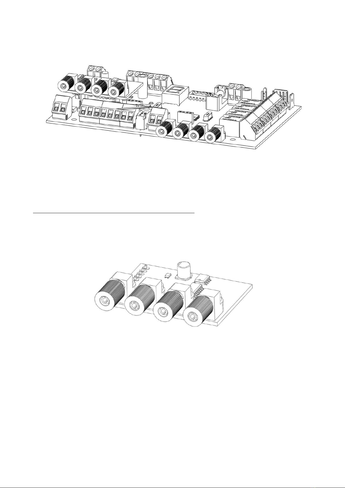
Concentrator module for fiber-optic Solar Defender (model ALM-6 14/6 15).........................6
Description of the concentrator module.............................................................................7
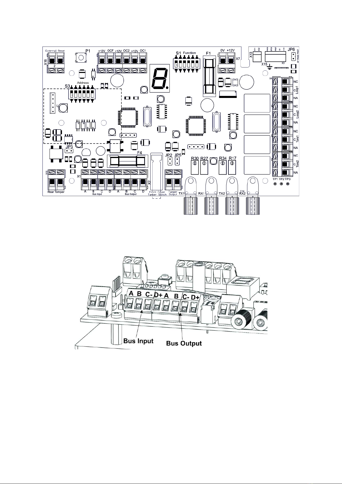
Bus Input A B C D terminal block.................................................................................
Bus Output A B C D terminal block...............................................................................
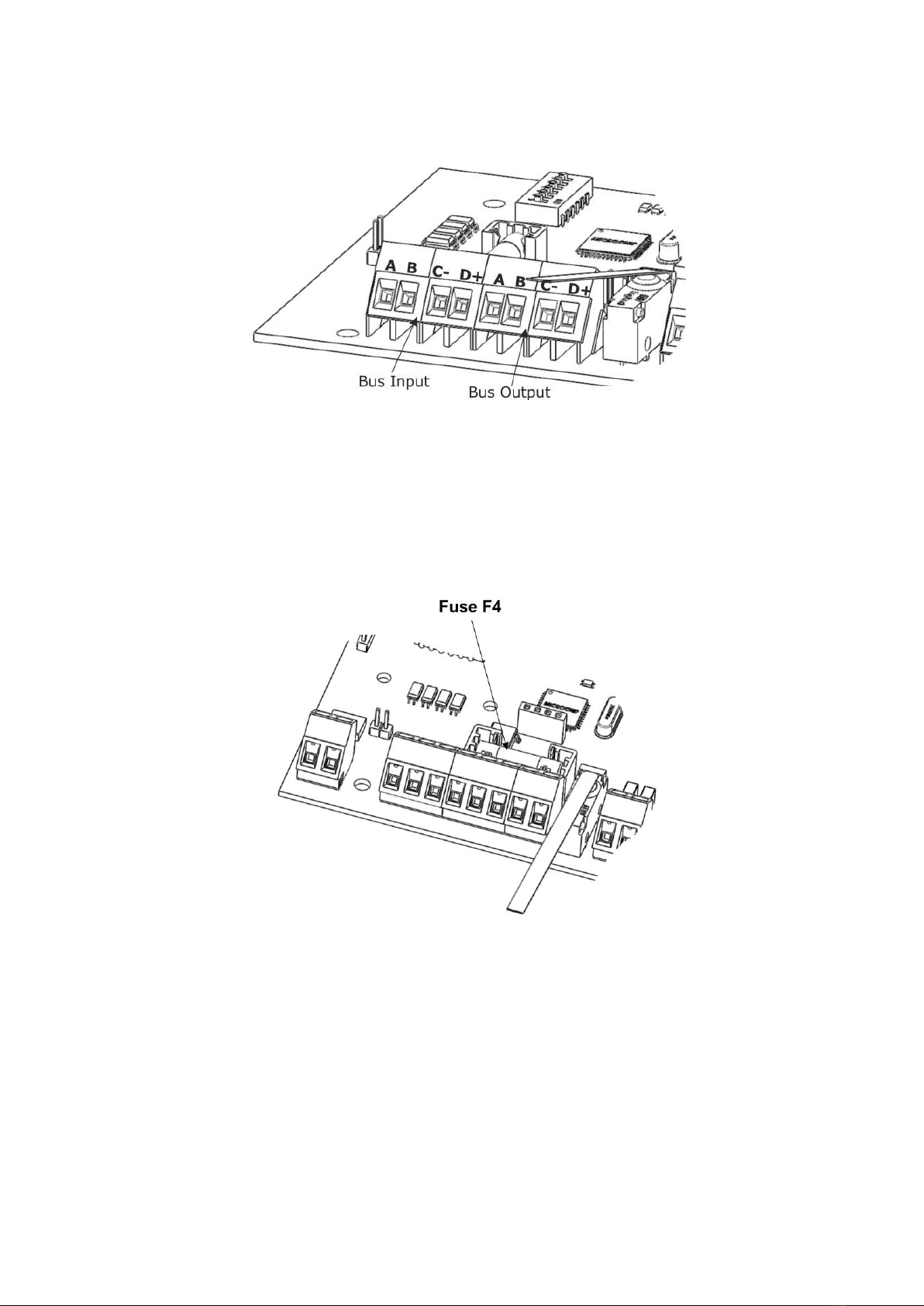
Fuse F4.....................................................................................................................9
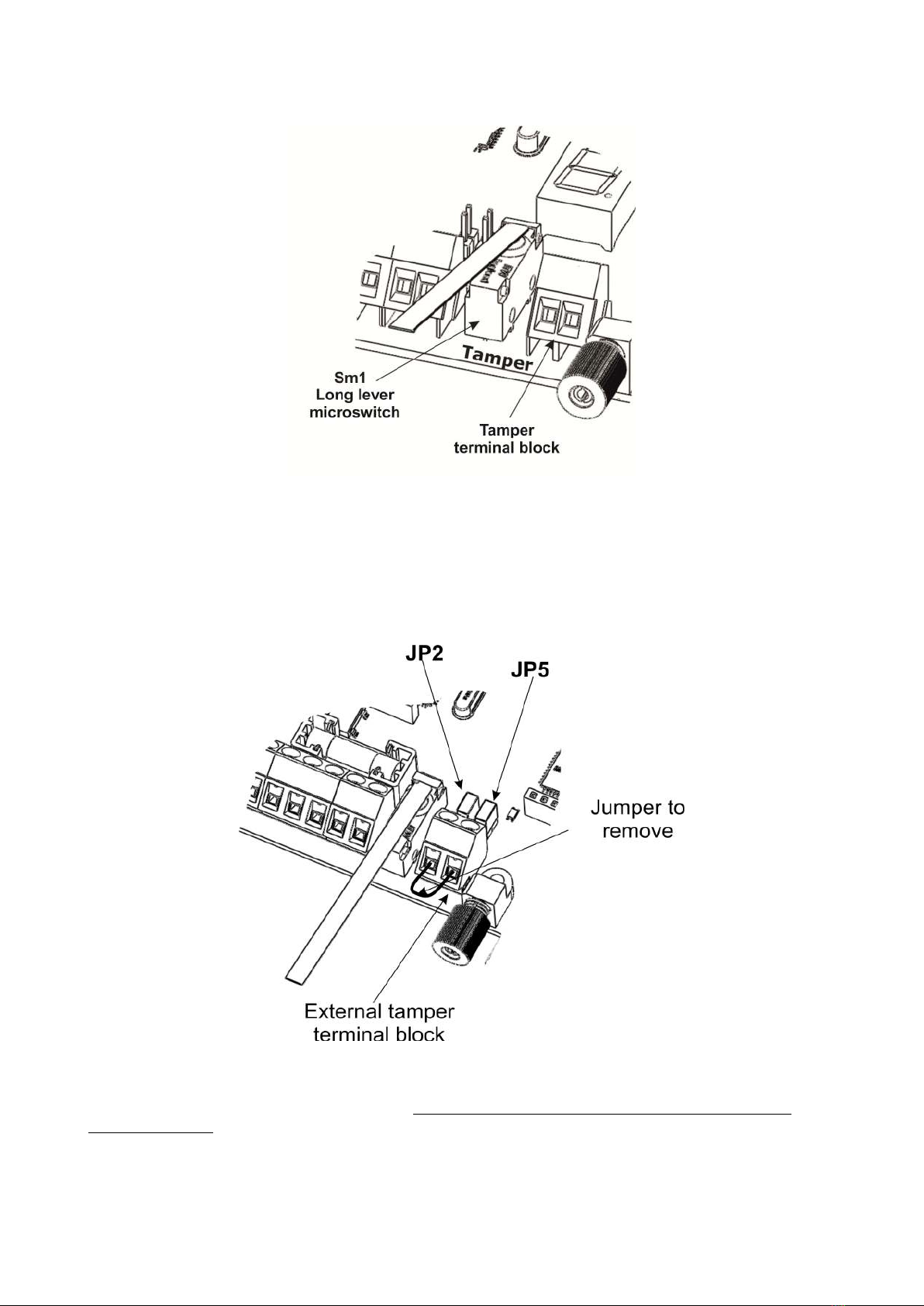
Tamper terminal block.................................................................................................9
Fiber Optic TX and RX...............................................................................................10
Cutting and torsion fiber signalling relay......................................................................11
Reset button and External Reset terminal block............................................................12
Open Collector OC1, OC2 and OCF outputs..................................................................12
Using the OCF Open Collector output......................................................................13
Use first mode..................................................................................................13
Use second mode.............................................................................................14
Use third mode.................................................................................................15
Auxiliary power supply X7 terminal block.....................................................................16
Fuse F1...................................................................................................................16
JP6 e JP3 Jumpers....................................................................................................16
Dip-switch SW2 Function...........................................................................................17
Loop fiber adjustment ALM-6 15 and ALM-6 14...............................................................1
Fiber loop calibration.................................................................................................19
Primary calibration................................................................................................19
Fine calibration.....................................................................................................19
Dip-switch S3 Address...............................................................................................22
Addressing operation................................................................................................23
Jumper JP3..............................................................................................................24
Seven Segments Display...........................................................................................24
Wiring inside the container ...........................................................................................24
Cable gland on the container .....................................................................................25
Connection and passing of the optical fiber .................................................................26
Minimum curvature of the fiber..............................................................................2
Power Supply features...................................................................................................2
Terminal blocks on power supply module.....................................................................29
Autonomy of operation with battery backup.....................................................................30
TECHNICAL SPECIFICATIONS.........................................................................................31
Note:..........................................................................................................................32
Declaration of Confirmity...............................................................................................35
Installation and Programming Manual V1.2 3

SAFETY PRECAUTIONS
The installation of the product must be performed by qualified personnel in accordance with
local laws and regulations on safety.
In agreement with the European Directive 2004/10 /EC (EMC), the product must be installed
using equipment, cables and accessories that allow it to meet the requirements of the Directive
for fixed installations.
The product must be connected to the mains supply by following the instructions in this
manual.
Keep physically separated extra low voltage wires, including the battery, the wire low voltage
(230Vac).
IMPORTANT
Only trained and authorized personnel can service the product, with the aim of making the
connections described in this manual. In case of failure do not attempt to repair the product or
the warranty will no longer be valid.
The opening of this unit may provide dangerous parts under tension. Remember to disconnect
the power before you get your hands on the power supply section.
It is recommended to periodically verify the proper functioning of the alarm system, however,
a reliable electronic alarm system will not prevent theft, tampering, fire, etc., but merely
reduce the risk that such situations occur.
ACCORDANCE WITH THE EUROPEAN DIRECTIVES
The product meets the essential requirements of European Directive 2004/10 /EC
(Electromagnetic Compatibility Directive - EMC) and is therefore consistent with the
harmonized standards EN 50130-4, EN 61000-6-3.
To connect to the 230V, use cables with greater than 0.5 mm and with an extra
jacket to ensure greater protection.
Installation and Programming Manual V1.2 4

FEATURES OF DEVICES
In this part of the manual lists the major hardware features and functions of the plastic optical
fiber devices ALM-6 15, ALM6 14 and fiber optic connection module to the RS-4 5 bus.
ALM6 15 is an antitheft device, fiber optic plastic double loop. It functions is based on cut and
torsion control of the optical fiber. It can work both in stand-alone (autonomous), using the
relay and open collector outputs for the onboard alarm cut or torsion fibers, in either RS-4 5
bus to send these reports directly to the central management unit ALM-6 00. Its housed in a
200x300x132 container, equipped with a supervised power supply with main supply and status
battery control. In BUS RS-4 5 mode the control unit ALM-6 00 receives alarms both cut and
torsion fiber, both the main supply 230Vac presence and status of internal battery of each
device connected to the system bus.
ALM6 14 has within the same circuit board with features identical to those of the ALM6 15,
but without the power module 230Vac. For this model, the device operates at 12V and is
housed in a 175x175x75 container.
ALM-6 15 and ALM-6 14 have the following characteristics:
1. Double-loop fiber, with 200 meters per loop, with cut and torsion management;
2. Torsion adjustment system for each loopmanagement;
3. Four relay outputs for reporting cut and torsion for each loopmanagement;
4. Open Collector output signal blocking operation of the concentratormanagement;
5. Dual mode, stand-alone, and RS-4 5 bus selectable via dip switches;
6. Seven-segment LED display for viewing of alarms and calibration of the device.
Installation and Programming Manual V1.2 5

EXPLODED VIEW
Installation and Programming Manual V1.2 6

Concentrator module for fiber-optic Solar Defender (model ALM-6814/6815)
The concentrator module ALM-6 14/6 15 manages 2 lines plastic optical fiber (POF - Plastic
Optical Fiber) from 200 meters by 2 loops. It can work in stand-alone or centralized mode on
RS-4 5 bus.
ALM-6 15: Fiber optic concentrator, with supervised power supply module.
ALM-6 14: Fiber optic concentrator without supervised power module.
This manual only refers to the stand-alone operation. For the operation on BUS refer to the
installation and programming manual of the ALM-6 00.
Modulo convertitore BUS-Fibra (optional)
The concentrator modules are designed to interface the RS-4 5 bus using a plastic optical fiber
converter module.
Note: The drive-BUS fiber will soon be available.
Installation and Programming Manual V1.2 7

De cription of the concentrator module
Bu Input A B C D terminal block
Terminal block for connecting the RS-4 5 bus from the central unit (For use on bus mode. In
stand-alone is not used)
A Data Bus "A" (green if you use the cable MARSS ALM-6021)
B Data Bus "B" (yellow if you use the cable MARSS ALM-6021)
C Negative power supply from central unit ALM-6 00 (black if you use the cable MARSS ALM-
6022 and any other cables)
D +24V Positive power supply from central unit ALM-6 00 (red if you use the cable MARSS
ALM-6022)
Installation and Programming Manual V1.2

Bu Output A B C D terminal block
Terminal block for connecting the RS-4 5 bus to the next concentrator module.
A Data Bus "A" (green if you use the cable MARSS ALM-6021)
B Data Bus "B" (yellow if you use the cable MARSS ALM-6021)
C Negative power supply to the next concentrator module (black if you use the cable MARSS
ALM-6022 and any other cables)
D +24V Positive power supply to the next concentrator module (red if you use the cable
MARSS ALM-6022)
Fu e F4
Fast Fuse 1A power protection from the bus RS-4 5.
Installation and Programming Manual V1.2 9

Tamper terminal block
The concentrator module has an internal long lever microswitch for tamper protection of the
container. If you use mode of operation on bus, the device will indicate tampering with the
control unit via BUS.
In standalone mode, you can use the terminal block for connection to any burglar alarm or
signaling device (telephone dialer, radio, etc. ..). In this case we must remove the jumpers JP2
and JP5.
Note: Both in the operation on bu , both in tand-alone, after the in tallation and
te ting of the concentrator, we mu t remove the jumper on the external tamper
terminal block. Leaving the jumper connected to the terminal, the tamper will remain
inactive.
Installation and Programming Manual V1.2 10

Fiber Optic TX and RX
The concentrator is equipped with 4 connectors fiber. 2 for TX and 2 for RX (no need to do fine
lapping prior to connection of the fiber).
TX and RX fiber are calibrated to the use of plastic optical fiber to a maximum length of 200
meters. When there is an interruption or a torsion of the fiber, the optical receiver detects the
change of transmitted light and communicates it to the concentrator module. In the bus
mode , the communication is directly with the central ALM-6 00.
Alarms cutting or torsion are identified by two different relays for loop for a total of four alarm
relays on board the concentrator.
Installation and Programming Manual V1.2 11

Cutting and tor ion fiber ignalling relay (Loop1-Tor 1 and Loop2-Tor 2)
The concentrator is equipped with four relays alarm signal.
Loop1: Alarm cut loop1
Loop2: Alarm cut Loop2
Tors1: Alarm torsion fiber loop1
Tors2: Alarm torsion fiber Loop2
The four relays are activated in case of breakage, cutting or torsion of the fiber. The cut and
torsion signaling activates the relay for alarm only if the two events occur at different times.
If cutting the fiber, will activate the corresponding alarm relay cut (Loop1 or Loop2).
If torsion occurs before and subsequently the cut, both relays will be activated.
The relay contacts can support a maximum load of 1A 250 AC or 24 DC 1A.
Re et button and External Re et terminal block
The S1 is used to reset the concentrator, after an alarm signal. You can also reset the device
(GSM dialer, etc ...) using the terminal block "External Reset." The command reset is
performed by applying a 12Vdc terminal block for a few seconds.
Note: The maximum voltage applied to the reset terminal block is 24Vdc.
Installation and Programming Manual V1.2 12

Open Collector OC1, OC2 and OCF output
Open collector output with a negative closing. It 'always on. Shuts down in case of blocking the
operation of the device or lack of power. The working scheme of this output is as follows:
When the transistor is in standby, on the collector there is no tension. When activated through
the resistance base, the transistor enters in conduction, giving a negative voltage output. To
test the output, just connect a multimeter between the positive and the collector (on the divice
is present a positive voltage of +12 V). When the open collector output is active between the
collector and the positive supply voltage of 12V will be measured.
Note : On the concentrator module is only active output OCF. The outputs OC1 and OC2 are
not currently used.
U ing the OCF Open Collector output
The output OCF (Open Collector Fault) is a security check of operation of the concentrator
module. Its always active until the concentrator is in operation. In case of lack of both power
supplies, battery and 230VAC (or fault of the fuse F1 to the concentrator without power
supervised ALM-6 14), or blocking the operation of one of the two microprocessors on board,
there OCF output will be no voltage. Its very important to use this output when using the
concentrator ALM6 15 and ALM6 14 in stand-alone mode. In bus mode these reports are
controlled by the central unit ALM-6 00.
Important Note: The u e OCF output i nece ary for the reporting of the failure of
the concentrator.
Will be illustrated three ways to use this output. These rules also apply for any open collector
output of any system, with close to negative.
Installation and Programming Manual V1.2 13

se first mode
12 cc relay connection to open collector output
This is the simplest way to connect an open collector output that closes to negative. On ALM-
6 15/6 14 the transistor is always on. The open collector output is turned off by the total lack
of power supply or locking the device. This affects the absorption of the device of about 20mA
(the absorption varies depending on the type of relay used).
Note: In the operation of the concentrator on BUS, all these reports are made automatically
by the central management ALM-6 00. This connection is used only for stand-alone mode.
se second mode
Direct connection of the open collector output on a generic alarm system input
You can connect the open collector output OCF directly to an alarm input of any burglar alarm
or telephone dialer that has the functional zones to negative. To test this, just check on the
Central, the dialer, or expansion of inputs, the continuity between the common alarm inputs
and the negative supply. If there is continuity, then you can connect the OCF as the diagram
above. 0V is any negative power of the concentrator ALM-6 15 / 6 14 (for convenience use
the negative power supply terminal X7 described on next page). Otherwise avoid this mode of
connection.
Note : In the operation of the concentrator on BUS, all these reports are made a utomatically
by the central management ALM-6 00. This connection is used only for stand-alone mode.
Installation and Programming Manual V1.2 14

se third mode
Open collector output connection to a separate relay from the concentrator module
The main problem of the first connection mode described above, is that the relay is always
active, increasing the absorption, per device, of about 20mA (depending on the type of relay
connected). To resolve this problem just use, in addition to the relay, some components easy
to find and use.
R1: Resistor 470ohm 1/4W 5%
R2: Resistor 15Kohm 1/4W 5%
T1: Transistor NPN as BC337B
D1: Diode as 1N4007
Relè: Relay with 12V DC coil
With this mode of connection, the relay will be activated only in case of power off or locking of
device operation.
Note : In the operation of the concentrator on BUS, all these reports are made a utomatically
by the central management ALM-6 00. This connection is used only for stand-alone mode.
Installation and Programming Manual V1.2 15

Auxiliary power upply X7 terminal block
The power supply on board, has a charging circuit with a battery charge test and functionality
test. In bus mode, the concentrators (only ALM-6 145) have power supply test and status
batteries alway active. In case of failure, is reported directly to the central ALM-6 00 through
the bus, the number of the concentrator with the bad power supply.
You can, however, use any other power supply 12V 1.5 A minimum of any brand by purchasing
the only fiber concentrator power module and supervised ALM-6 14. In this case it is not
possible to check the presence of 230Vac and efficiency of the battery.
Fu e F1
Fuse 1A fast type, for auxiliary power supply protection. Replace with same value only.
JP6 e JP3 Jumper
JP3: Activate the line termination. It should be activated only if requested by the Technical
Service MARSS
JP6: Enable the power on of the concentrator in stand-alone mode. In BUS mode the jumper
must be removed.
Installation and Programming Manual V1.2 16

Dip- witch SW2 Function
The dip-switch SW2 has 6 microswitches. Microswitch 2 is not used
The microswitch 1 is used to disable the loop fiber 2. This function is used when we use fiber
loop 1 only.
Micro witch 1 ON => Loop2 Disabled (Segment on Display on)
Micro witch 1 OFF => Loop2 Enabled (Segment on Display off)
The microswitches 3, 4, 5 and 6 are used to activate the control and calibration of the reading
of the fiber. This way you can be sure of the best read / signal transmission through the fiber.
Installation and Programming Manual V1.2 17

Loop fiber adju tment ALM-6815 and ALM-6814
After installation of the fiber (see page 26 for connecting and passing fiber) and the
concentrator module, both loop fiber must be calibrated. To do this, we use the microswitches
3, 4, 5, 6 on dip-switch function and trimmer R30, R27, R34 and R17.
Dip-switches and trimmers needed for calibration
S1 Dip-switch
•witch3 enabling calibration loop1
•witch4 enabling calibration loop2
•witch5 enabling fine calibration loop1
•witch6 enabling fine calibration loop2
Adjustment trimmers
•R30 Primary calibration loop1
•R27 Fine calibration loop1
•R34 Primary calibration loop2
•R17 Fine calibration loop2
Note: If you use only the loop1 is not necessary to calibrate the Loop2
Installation and Programming Manual V1.2 1

Fiber loop calibration
For the primary calibration of the loop fiber proceed as follows. On dip-switch “Function”:
1. Ensure that the microswitch 3, 4, 5 and 6 are OFF;
2. Turn ON the microswitch 3 to enable adjustment of loop1;
Adjust the trimmer R30 until you see on the display, the value close to 5. To do this
bring the value of reading on the display 5 and then adjust back around a quarter of the
trimmer. The display will have to remains displayed the number 5 and not 4.
3. Return to OFF the microswitch 3;
4. Turn ON the microswitch 4 to enable adjustment of Loop2;
Adjust the trimmer R34 until you see on the display, the value close to 5. To do this
bring the value of reading on the display 5 and then adjust back around a quarter of
the trimmer. The display will have to remains displayed the number 5 and not 4.
5. Return to OFF the microswitch 4.
Once you have the value close to 5 with the primary regulation loop of fiber is possible to
switch to fine calibration. Proceed as follows:
1. Ensure that the microswitch 3, 4, 5 and 6 are OFF;
2. Turn ON the microswitch 5 to enable the fine calibration of loop1;
•Adjust the trimmer R27 until you see on the display
The segments “g” e “p” indicate the optimal adjustment of the fiber loop.
Installation and Programming Manual V1.2 19

When adjusting the trimmer, the segment "a" and the segment "d" indicate whether
it is increasing or decreasing the value of reading. In detail:
The segment "a" blinks during adjustment if the value of reading
increases.
The segment "d" blinks during adjustment if the value of reading
decreases.
Too high or too low value in reading are identified with the segments "f" and "e"
turned on
3. Turn OFF the microswitch 5;
Installation and Programming Manual V1.2 20
This manual suits for next models
1
Table of contents