RDCI Series – All DC Inverter Outdoor Units 6 720 862 438 (2016/04)
OPERATION AND PERFORMANCE | 3
Table 2-1
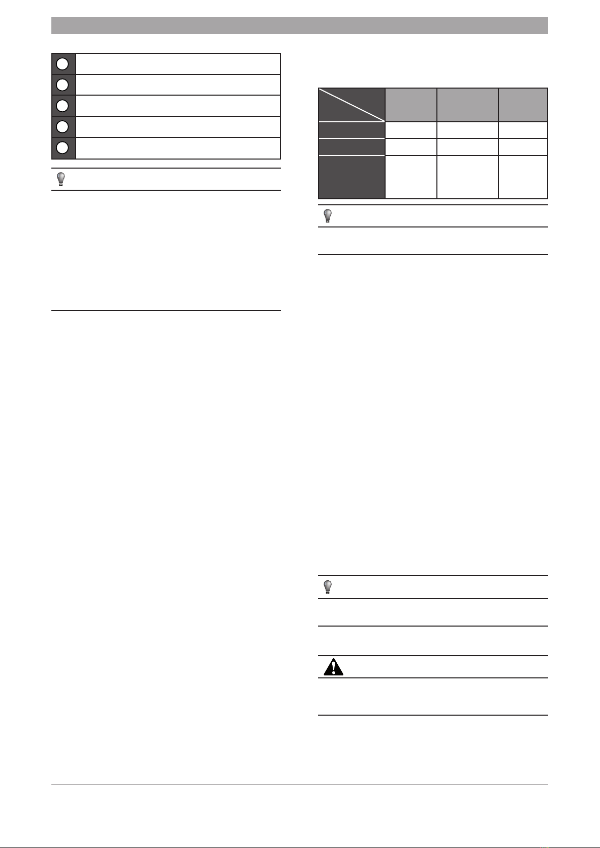
1Air inlet (Located on the Left, right and rear sides.)
2Refrigerant pipe connective opening or outlet for wires
3Refrigerant pipe connective opening or outlet for wires
4Floor mount
5Air outlet (Located on the top of the unit, which will expel hot or cold air
depending on the demand.)
NOTE
■All the pictures in this manual are for explanation purposes only.
Your appliance will differ according to installation and application.
■On completion of installing the air conditioning unit, ensure
the electrical power supply is on to the unit for the minimum of
12hrs prior to operation. Failure to do so, may result in product
failure. Should the units electrical power supply be interrupted for
a period of more than 24hrs, then the above process will have to
be repeated.
■Ensure the air inlets and outlets are not blocked. This will decrease
the operational performance of the unit and could lead to product
failure.
3. OPERATION AND PERFORMANCE
■Cooling and heating operation
•This unit can perform simultaneous cooling and heating of the
indoor units pending on the demand. However the units installed
downstream of the S Box modules on the same refrigeration circuit
cannot perform heating and cooling simultaneously. A fault will be
will be displayed.
1. When set as the Heating Priority Mode, the indoor unit on Cooling
Mode will stop and there will be Standby or in Priority displayed on
the control panel. Those indoor units which are running on Heating
Mode will run continuously.
2. When the Cooling Priority Mode has been set, the indoor unit
on Heating Mode will stop and there will be Standby or No Priority
displayed on the control panel. Those indoor units which are
running on Cooling Mode will run continuously.
3. When priority mode is selected, the first indoor unit turned
on will be master and will override all the indoor units. If the first
unit turned on (master) is in heating mode, then all other indoor
units will be in heating mode or in standby mode. This process is
the same for cooling should the first unit (master) select a cooling
demand. Should a demand be selected on an indoor unit which is
different to the ‚master‘ indoor units demand, an error code will
appear on the controller.
■Features of heating operation
•When heating mode is selected, the unit will not blow warm air out
immediately. It can take 5-10 minutes to warm up depending on the
ambient temperature.
•During operation, the fan motor in the outdoor unit may stop
running under high temperatures.
•When a indoor unit is in standby, the fan will stop running to avoid
draft.
■Defrost in the heating operation
•During heating operation, frost can accumulate on the outdoor unit.
To increase efficiency, the unit will start defrosting automatcally
for approximately 2 - 10minutes depending on the amount of
accumulated frost. The frost will then thaw and drip away from the
unit.
•During defrosting, both the outdoor unit and indoor unit fans will
periodically stop.
■Operation conditions
•For optimum performance operate the system under the following
temperatures:
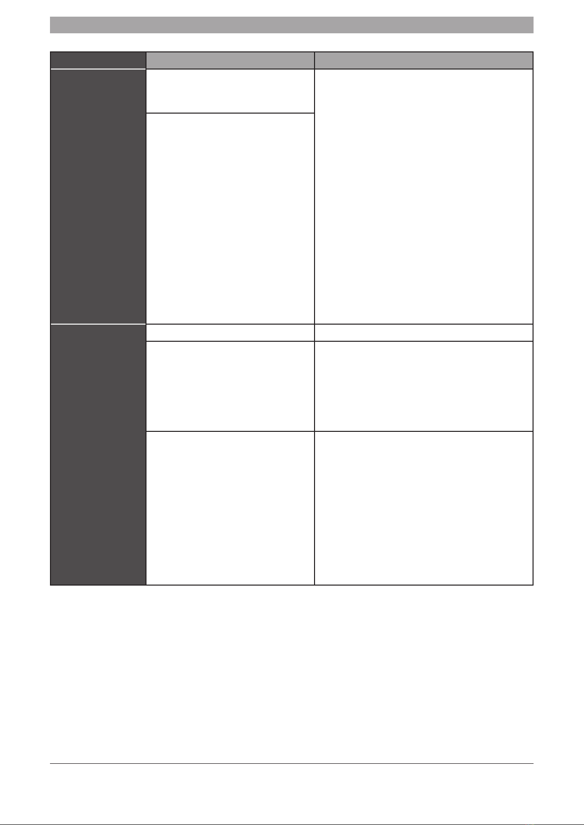
Table 3-1
Temperature
Mode
Outdoor
temperature
Indoor
temperature
Room
relative
humidity
Cooling mode -5°C ~ 48°C 17°C ~ 32°C below 80%
Heating mode -20°C ~ 24°C ≤27°C
Mixed mode -5°C ~ 24°C
Cooling mode
17°C ~ 32°C
Heating mode
≤27°C
NOTE
When the unit is running outside it‘s normal parameters, the unit
will shut down as a protection device is fitted inside the unit.
■Protection Device
This protection device will stop the unit automatically. When
protection device is activated, the running indicator flashes.
The protection device may have been activated as a result of the
following circumstances.
■Cooling operation:
•The air inlet or air outlet on the outdoor unit is blocked.
•Strong winds are continuously blowing on the air outlet.
■Heating operation:
•The indoor unit filters are blocked.
■Electrical power to the unit is interrupted
•Should the electrical power supply be interrupted, all operation of
the unit will stop. Isolate the main electrical supply to the unit until
the electrical power supply has returned and stabilised.
•When the electrical power supply is re-established, the controller
will flash and will begin to initialise.
•Push the ON/OFF button again if you want to restart the unit
should the initialisation not work first time.
■Communication problem
Should the communication between units be lost, switch off the
electrical power supply to all indoor/outdoor units. Firstly re-
instate the power to the indoor units, then re-instate the power to
the outdoor unit.
■Heating capacity
•If the outdoor ambient temperature decreases, then the output of
heat discharged from the indoor units will also decrease.
•In cold temperatures the unit will default to heating mode only.
NOTE
Do not attempt to re-activate the electrical power supply to the unit
via the protection device until the problem has been solved.
4. TROUBLESHOOTING
CAUTION
■Should a malfunction occur, isolate the electrical power supply to
both the indoor and outdoor units. Or should the fuse or leakage
protector frequently trip. Contact a competent person.
Please read the following basic checks