Marstair A2LCELLARMATCH User manual

55908059-01
A2LCELLARMATCH TECHNICAL MANUAL

55908059-01
2
Section
Page
1
General Information
1A General Information
3
1B General Installation procedure
4
2
SMC Condensing Units
2A Specification
5
2B Performance Data.
6
2C Mounting, Dimensions & Weights
6
2D Pipework Installation.
8
2E Pressure Testing
9
2F Evacuating
9
2G Electrical & Fuses
9
2H Refrigerant
10
2G Condensing Unit Wiring Diagrams
12
2H Electronic Valve Driver Interface
13
2I Electronic Valve Driver Parameters
15
2J Eco Design Information Tables
20
2K Component Identification SMC+
22
2L Condensing Unit Maintenance
23
3
Evaporators
3A Component Identification
24
3B Unit Dimensions
25
3C Specification
26
3D Evaporator Installation
27
3E Evaporator Operation
28
3F Maintenance
29
3G Alarm Installation
30
3H Evaporator Wiring Diagram
31
3I Refrigerant System Schematic Diagram
31
4
System selection process
32
5
Spares
32
6
End of life requirements
32
7
Installation risk assessment
33
CONTENTS

55908059-01
3
1A GENERAL INFORMATION
Installation must be carried out in accordance with the Marstair installation manual, EN 378 and national codes and
guidance.
1. Installation work on this equipment to be completed by F Gas certified Technicians who are fully
conversant with the appropriate Refrigeration and Electrical practices and have sound knowledge of
current Industrial Safe Working practices. It is also advisable that technicians hold the ACRIB
Understanding the properties of flammable refrigerants (A2L, A2 and A3) qualification.
NOTE: it is the responsibility of the operator to ensure the technician is certified to the correct standard
(EN13313 or equivalent).
2. These units are supplied with a holding charge of oxygen free nitrogen and polyolester oil. Do not mix oils
or refrigerants.
3. These units when installed contain live electrical components, moving parts and refrigerant under pressure.
Always site out of reach of children and protect from vandalism.
4. The data plate only gives information for the individual indoor or outdoor unit. For system details add input
power and current of indoor and outdoor unit, including any heater load.
5. The refrigerant used should be identified by locating a refrigerant label on the unit case
6. A suitable risk assessment of the installation must be carried out. This ensures a safe working
environment is maintained in accordance with The Dangerous Substances and Explosive Atmosphere
Regulations and the Management of Health and Safety at Work Regulations. A step by step guidance
template is provided within these instructions.
7. The condensing unit must be installed outside.
8. Systems uses R454C refrigerant which is classed as an A2L flammable gas
1 –GENERAL INFORMATION

55908059-01
4
1B GENERAL INSTALLATION PROCEDURE
oCarry out “step by step” or full risk assessment
oEnsure that no sources of ignition are present during installation
oOnly certified natural persons should be present during the installation
oCorrect selection of tools and equipment compatible with A2L refrigerants. This should include the
following:
▪Flammable gas leak detector placed at a low level next to the service valves of the
condensing unit.
▪If adequate natural ventilation is not present throughout the installation process, then forced
ventilation should be employed via an A2L compatible or ATEX rated fan and motor.
▪When pressure testing through a refrigerant manifold, ensure that it is suitable for the
pressure (no sight glass fitted).
▪A2L compatible 2 stage vacuum pump, exhausted to a safe well ventilated area and away
from any source of ignition (check exhaust fumes with flammable gas leak detector).
▪R454C bottle adaptor (left handed female and right handed male connections DIN477-1
21.8mm LH, External, 14 T.P.I).
▪All refrigerant hoses should be as short as possible and have self-closing or ball valve
connections in accordance with BS EN 378.
▪If additional refrigerant is to be added, charge in liquid state and ensure a flammable gas
leak detector is positioned at a low level near the connections. (If the flammable gas leak
detector indicates the presence of a flammable atmosphere, do not energise or de-energise
any electrical components until a safe environment has been ensured.)
oLeak checking the system in accordance with EN 1516/2017 directly after installation.
oIf a leak is discovered, energise the flammable gas leak detector and place at a low level near
connections to the recovery machine and cylinder. Connect an A2L compatible recovery machine
and recover into a suitable recovery cylinder (red painted cylinder valve guard and shoulder) in
accordance with BS EN 378.

55908059-01
5
2A SPECIFICATION.
SME
20
30
45
50
80
Nominal cooling capacity (-10°C evaporating temp & 32°C
ambient temp) R454C
kW
1.53
1.78
2.96
4.17
5.26
1 Ph (230V 50Hz) compressor load only (at nominal cooling capacity)
Power (nominal)
kW
0.83
0.98
N/A
N/A
N/A
Starting current LRA
A
33
42.2
N/A
N/A
N/A
Nominal current FLA
A
5.8
6.4
N/A
N/A
N/A
3Ph (400v 50Hz) compressor load only (at nominal cooling capacity)
Power (nominal)
kW
N/A
N/A
1.36
1.75
2.18
Starting current LRA
A
N/A
N/A
26
32
46
Nominal current FLA
A
N/A
N/A
4.2
5.5
6.8
Sound Pressure Levels (SPL) at 10m distance in free field conditions @ 27°C external ambient.
dBA
34
34
33
33
34
NR
28
28
27
27
27
Condenser fan (1Ph 230V 50Hz)
Airflow (max speed)
m³/s
0.323
0.713
0.713
0.713
0.713
Airflow motor rating
kW
0.065
0.13
0.13
0.13
0.13
Nominal current FLA
A
0.4
0.6
0.6
0.6
0.6
Fans: No. x diameter
#x
1x350
1x457
1x457
1x457
1x457
mm
Fans max speed
r.p.m
940
940
940
940
940
2 - SMC CONDENSING UNITS

55908059-01
6
2B PERFORMANCE DATA.
MODEL
Evaporating temperature
Ambient
temperature
-20
-15
-10
-5
0
SMC 20
27
0.95
1.25
1.69
2.02
2.59
30
0.90
1.18
1.60
1.91
2.44
32
0.86
1.13
1.54
1.84
2.35
35
0.81
1.07
1.45
1.73
2.22
38
0.77
1.01
1.37
1.63
2.09
40
0.74
0.97
1.31
1.57
2.01
SMC 30
27
1.10
1.44
1.96
2.34
3.00
30
1.04
1.36
1.85
2.21
2.83
32
1.00
1.31
1.78
2.13
2.72
35
0.94
1.24
1.68
2.00
2.57
38
0.89
1.16
1.58
1.89
2.42
40
0.85
1.12
1.52
1.81
2.32
SMC 45
27
2.03
2.55
3.16
3.88
4.72
30
1.95
2.45
3.04
3.74
4.55
32
1.90
2.38
2.96
3.64
4.44
35
1.81
2.28
2.84
3.50
4.26
38
1.72
2.18
2.71
3.35
4.09
40
1.67
2.11
2.63
3.25
3.97
SMC 50
27
2.86
3.60
4.46
5.47
6.66
30
2.75
3.46
4.29
5.28
6.42
32
2.68
3.36
4.18
5.13
6.26
35
2.55
3.22
4.01
4.94
6.01
38
2.43
3.08
3.82
4.73
5.77
40
2.36
2.98
3.71
4.58
5.60
SMC 80
27
3.61
4.53
5.62
6.90
8.39
30
3.47
4.36
5.41
6.65
8.09
32
3.38
4.23
5.26
6.47
7.90
35
3.22
4.05
5.05
6.22
7.58
38
3.06
3.88
4.82
5.96
7.27
40
2.97
3.75
4.68
5.78
7.06
2C MOUNTING, DIMENSIONS & WEIGHTS.
These units are designed to stand on a flat surface. If the unit is to be wall mounted the following kits are available.
KIT
SMC 15-80
Mounting Bracket
55021100
Whether floor or wall mounted, it is essential that the mounting surface is capable of supporting the unit weight. Leave
space around the unit for air circulation and access for installation and maintenance.
Dimensions in mm.

55908059-01
7
Condensing unit to be installed outside and not in an enclosed area.
Smoking and naked flames should be prohibited around the area around the condensing unit.
Packed weights
Model
Dimensions
Weight
SMC
Width
Depth
Height
1ph
3ph
20
1060
340
620
49
30
1060
340
620
50
45
1160
390
720
63
50
1160
390
720
66
80
1160
390
720
68
SMC 20-80 (Dimensions in mm.)
Model
Dimensions
Weight
SMC
A
B
C
D
E
F
G
H
1ph
3ph
20
900
300
560
525
185
117
296
274
47
30
900
300
560
525
185
117
296
274
48
50
1000
350
660
495
250
117
346
324
64
80
1000
350
660
495
250
117
346
324
66

55908059-01
8
2D PIPEWORK INSTALLATION.
Supplied Sweat connections
Model SMC
Size
20
30
45
50
80
Expansion
3/8
3/8
3/8
1/2
1/2
Suction
1/2
1/2
1/2
1/2
5/8
The installation section of the risk assessment template or equivalent should be carried out before commencing
installation.
When installing a split refrigeration system, all interconnecting refrigeration pipework must be manufactured, jointed,
tested, insulated and installed in such a way as to ensure that damage cannot occur during normal, service and
maintenance operations that may cause a rupture and subsequent leakage.
It is advisable, wherever possible, that brazed or permanent mechanical joints are used when jointing refrigeration
pipework designed for an A2L refrigerant.
MAXIMUM PIPE RUNS
80m maximum including 20m lift (50m SMC 15-20). There will be no significant loss of capacity for extended pipe runs
provided pipes are correctly sized.
CALCULATING EQUIVALENT LENGTHS
The effects of bends and fittings must be taken into account.
Pipe sizes are based on:
Minimum of 2.5 m/s (500 fpm) suction gas velocity for horizontal or downflow.
Minimum of 5.0 m/s (1000 fpm) suction gas velocity for upflow.
Maximum of 20.0 m/s (4000 fpm) suction gas.
Where vertical risers exceed 3m, oil traps must be formed in the pipe. This will help ensure that oil returns to the
compressor. Typically fit an oil trap every 3m with a trap at the bottom of the riser.
GOOD PRACTICE
Keep pipe runs as short as possible.
Avoid sharp bends
Fully insulate both suction and expansion lines including mechanical connections
Try to avoid running pipes through hot areas.
Suction pipe size
Expansion pipe size
SMC
3/8"
1/2"
5/8"
3/4"
7/8"
1-1/8"
1/4"
3/8"
1/2"
5/8"
3/4"
20
7.5
23
50
50
30
15
50
80
50
80
45
10
36
80
7.5
80
50
7.5
18
50
80
7.5
50
80
80
11
30
80
50
80
1. Connecting the pipework:
a. Release the nitrogen holding charge by slowly opening the valves using a 5mm or 8mm allen key.
b. Ensure the suction line is fully insulated.
c. Connect the pipework between the units. Do not leave pipes ends, valves etc open to the atmosphere.
d. Use a protective shield to avoid scorching the side panel.

55908059-01
9
2E PRESSURE TESTING
The pressure testing section of the risk assessment template or equivalent should be carried out before commencing
pressure testing.
Pressure and leak testing of the system should be completed in accordance with EN 378.
Note: The interconnecting pipework and evaporator are all on the low-pressure side of the system. The only high-
pressure side of the system is within the condensing unit. Therefore, the pressure and leak testing of the pipework can
be treated as such within EN 378.
The matched MBMT evaporators all have a maximum allowable pressure of 25Barg
The condensing unit is fitted with a high-pressure limiting device
SMC20-30 = 23Bar
SMC45-80 = 26Bar
The condensing unit has a pressure relief valve is set to 29.5Bar which is equal to the condensing unit maximum
allowable pressure do not exceed this pressure if testing the condensing unit.
2F EVACUATING
The Evacuation section of the risk assessment template or equivalent should be carried out before commencing
Evacuation.
With the valves open, connect a vacuum pump to the service ports on the outdoor unit valves. Evacuate the
interconnecting pipework and indoor unit to 1000 microns (1 Torr) or better. Allow this to be held for a minimum of 15
minutes.
2G ELECTRICAL & FUSES
The installer supplies mains, control and interconnecting cables: equipment must be earthed.
Wiring must be carried out in accordance with local and national codes.
Mains supply cables must be size compatible with the recommended fuse.
Cable clamps for use with stranded cables are supplied in units 15 - 100 and should be used to secure incoming/outgoing
cables. Installers must supply a method of securing solid sheathed cables.
THREE PHASE UNITS WITH SCROLL COMPRESSORS:
On 3 Ph units sizes it is possible for the scroll compressor to run backwards.
This becomes obvious on start up - the compressor will not develop a normal running pressure differential and the top will
not become warm: it may be excessively noisy. If this happens, switch off the mains power and exchange the two supply
phases not connected to the indoor unit. This will correct the rotation.
FUSES: The system and its supply/interconnecting wiring must be protected by fuses, preferably High Rupture Current
(HRC) motor rated types (to BS EN60269) or miniature circuit breakers to (BS EN60898) or local codes having similar
time lag characteristics, that allow starting of the compressor yet still afford close overcurrent protection under running
conditions. The ratings below are for HRC motor rated fuses.
1PH Fuse
SMC
20
30
Fuse
16
16
3PH Fuse
SMC
45
50
80
Fuse
10
10
10
The ratings are for the outdoor unit only. Currents for the indoor units including heaters if applicable should be noted and
the fuse size increased pro-rata if using same supply.

55908059-01
10
2H REFRIGERANT
Charging the system
The charging of refrigerant section of the risk assessment template or equivalent should be carried out before
commencing refrigerant charging.
1. Evacuate the system and interconnecting pipework ensuring the service valves are fully open.
2. Allow the evacuated system to draw in the majority of the refrigerant charge.
3. The final charge should be adjusted with the system running.
4. All units are fitted with head pressure control. The link wire across the orange terminals allows the fan to operate at full
speed. THIS SHOULD BE REMOVED AFTER CHARGING
5. A random start delay of up to 1 minute occurs when mains is first applied. A 3 minute delay occurs between successive
compressor operations on all systems.
6. Refrigerant and polyolester oil should be introduced through the Schrader valve the service port on the suction service
valve on the outdoor unit. Ensure the refrigerant is the correct type, as shown on the rating plate. R454C must
always be added in the liquid state.
7. Run the system for a few minutes to allow it to stabilize. Check suction and head pressures.
8. Systems should not be overcharged, to avoid liquid return to the compressor
9. HEAD PRESSURE CONTROL ALCO (FSY-42S) & SAGINOMIYA (XGE-4C)
The head pressure controller is factory set to suit the refrigerant. It may be necessary to adjust this to suit site conditions,
to raise or lower the nominal head pressure.
ALCO (FSY-42S)
a. With the system switched off, connect a high pressure gauge to the liquid line service valve.
b. Switch on the system and run for a few minutes to stabilise.
c. The head pressure should be approximately:
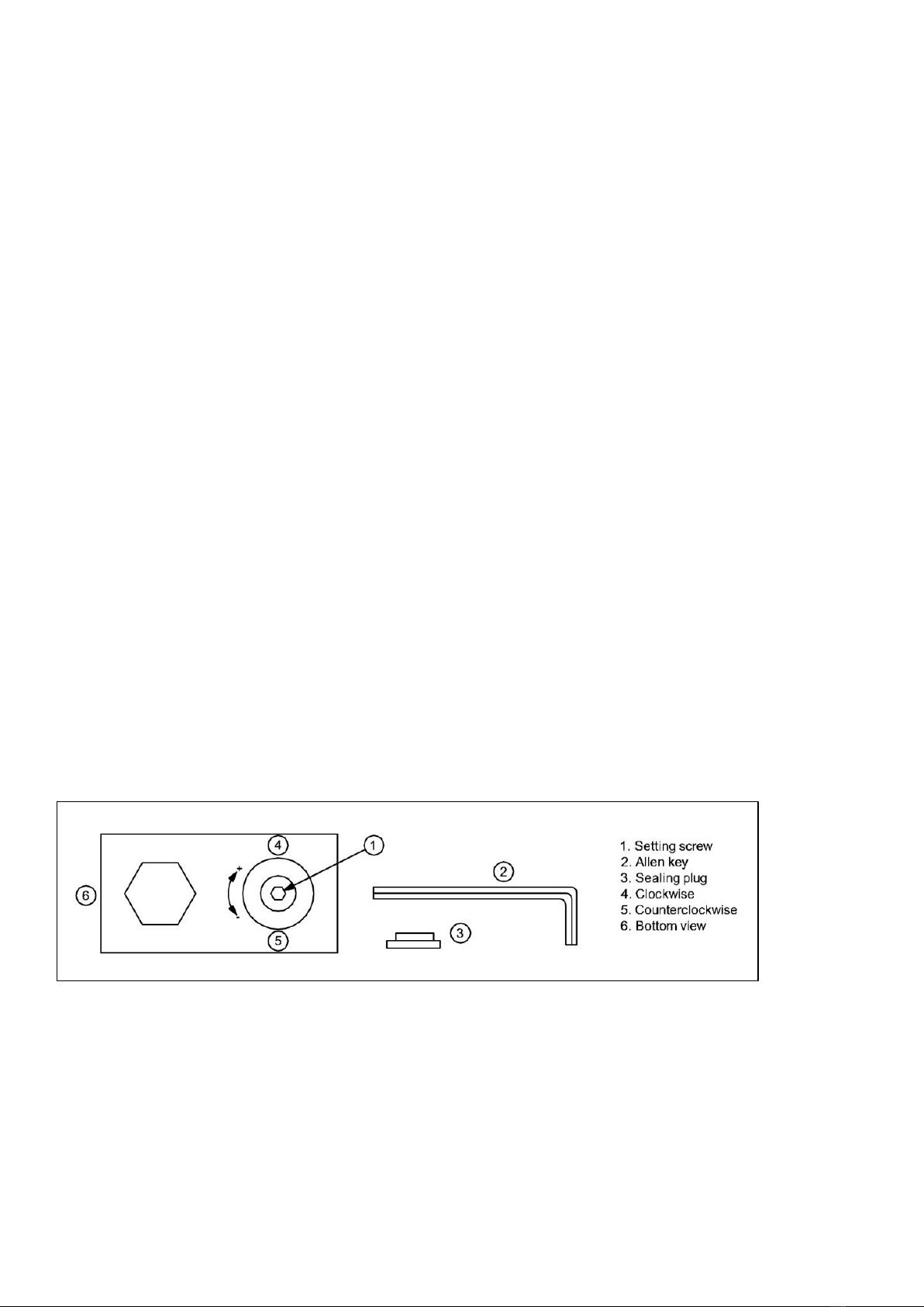
R454C: 210-220 psig (14.0-15.2barg) to achieve this remove sealing plug and insert 2mm or 5/64”
allen key into setting screw. Turn allen key clockwise (+) or counter clockwise (-) to readjust the setting.
NOTE: The condenser fan may stop if the operating pressure drops below 200 psig (13.8 barg)
Do not turn setting screw more than 3 turns clockwise (+3).
Pressure changes per turn of adjusting screw:
Pressure change: 9.2 … 21.2 bar:
Clockwise ~ +2,5 bar, counter clockwise ~ -2,5 bar
After adjustment, re-insert sealing plug and make sure that it is properly fitted. IP65 protection
requires firmly sealed plug
NOTES:
Tolerances for condensing temperatures setpoint: ±2K

55908059-01
11
SAGINOMIYA (XGE-4C)
R454C: 210-220 psig (14.0-15.2barg) to achieve this turn the range adjusting screw clockwise (+)
for increasing the setting value or counter clockwise (-) for decreasing the setting value.
Pressure changes per 1 turn of adjusting screw:
Pressure change: 10 … 25bar:
Clockwise ~ +1.5 bar, counter clockwise ~ -1.5 ba

55908059-01
12
2G CONDENSING UNIT WIRING DIAGRAMS

55908059-01
13
2H ELECTRONIC VALVE DRIVER INTERFACE
Note: The Electronic valve will be factory set to run at 6°C

55908059-01
14

55908059-01
15
2I ELECTRONIC VALVE DRIVER PARAMETERS
CONFIGURATION
A
Network address
pLAN: 30
others: 198
1
207
-
I
11
138
A
Refrigerant:
0= user defined;
1=R22 2=R134a 3=R404A 4=R407C
5= R410A
6=R507A 7=R290 8=R600 9=R600a
10= R717
11=R744 12=R728 13=R1270 14= R417A 15=R422D
16= R413A 17= R422A 18=R423A 19= R407A 20=R427A
21= R245FA 22=R407F 23=R32
24=HTR01 25=HTR02
26=R23 27=R1234yf 28=R1234ze 29=R455A 30=R170
31=R442A 32=R447A 33=R448A 34=R449A 35=R450A
36 = R452A 37 = R508B 38 =R452B 39=R513A 40=R454B
0 = User
Defined
-
-
-
I
13
140
A
Valve:
0= userdefined 13=SporlanSEH175
1=CARELE
X
V
14=Danfoss ETS12.5-25B
2=AlcoEX4 15=Danfoss ETS 50B
3=AlcoEX5 16=Danfoss ETS100B
4=AlcoEX6
17= Danfoss ETS250
5=AlcoEX7
18= Danfoss ETS400
6=AlcoEX8330Hzrecommend 19=TwoE
X
VCARELconnected
CAREL
together
7= Alco EX8 500Hz specific Alco 20= Sporlan SER(I)G,J,K
8=SporlanSEI0.5-11
21=DanfossCCM10-20-30
9=SporlanSER1.5-20
22=Danfoss CCM 40
10=SporlanSEI30 23=Danfoss CCM T2-4-8
11=SporlanSEI50
24=Disabled
12= Sporlan SEH 100
1 = CAREL E
X
V
-
-
-
I
14
141
A
Probe S1: 0= user defined
Ratiometric(OUT=0…5 V) Electronic (OUT=4…20mA)
1=-1…4,2barg 8= -0,5…7barg
2=-0,4…9,3 barg
9= 0…10 barg
3=-1…9,3barg
10= 0…18,2 bar
4=0…17,3barg
11=0…25 barg
5=0,85…34,2 barg 12=0…30 barg
6=0…34,5barg 13= 0…44,8barg
7=0…45 barg
14=remoto,-0,5…7 barg
15=remoto,0…10barg
16=remoto,0…18,2 barg
17=remoto,0…25barg
18=remoto,0…30barg
19=remoto,0…44,8 barg
20= Segnale esterno 4…20 mA
21= -1…12,8 barg
22= 0…20,7 barg
23= 1,86…43,0 barg
24=LivelloliquidoCAREL
25=0...60,0barg
26=0...90,0barg
Ratiometric:
4 = 0to17.3
barg
-
-
-
I
16
143
A
Main control:
0= user defined
1= Centralized cabinet/cold room
2=Selfcontainedcabinet/coldroom
3= Perturbated cabinet/control room
4= Subcritical CO
2
cabinet/cold room
5= R404A condenser for subcritical CO
2
6=ACorchillerwithplateevaporator
7= AC or chiller with shell tube evaporator
8=ACorchillerwithbatterycoilevaporator
9=ACorchillerwithvariablecoolingcapacity
10=ACorchillerperturbatedunit
11= EPR Back pressure
12=Hotgasby-passbypressure
13=Hotgasby-passbytemperature
14=transcriticalCO2gascooler
15= analog positioner (4 to 20 mA)
16= analog positioner (0 to10 V)
17= AC/chiller or cabinet/cold room with adaptative regulation
18= AC or chiller with Digital Scroll compressor
19= AC/chiller with BLDC compressor (*)
20=superheatregulationwith2temperatureprobes
21= I/OexpanderforpCO
22= Programmable SH regulation
23= Programmable special regulation
24= Programmable positioner
25= Evaporator liquid level regulation with CAREL sensor
26= Condenser liquid level regulation with CAREL sensor
(*)= only for controls for CAREL valves
9=ACor
chillerwith
variable
cooling
capacity
-
-
-
I
15
142

55908059-01
16
5rt
A
Probe S2:
1 = CAREL
NTC
-
-
-
I
17
144
0= user defined
1= NTC CAREL
2=
CAREL NTC- HT high
3= combined NTC SPKP**T0
4= 0 to 10V external signal
5=NTC–LTCARELlowtemperature
A
Auxiliary control:
0= user defined
1= Disabled
2=highcondensingtemperatureprotectiononS3probe
3=modulatingthermostatonS4probe
4=backupprobesonS3andS4
5,6,7=Reserved
8= Subcooling measurement
9=InversehighcondensationtemperatureprotectiononS3probe
10=Reserved
Disabled
-
-
-
I
18
145
A
Relay configuration:
1= Disabled
2=alarmrelay(openedincaseofalarm)
3=Solenoidvalverelay(openinstandby)
4=valve+alarmrelay(openedinstand-byandcontrolalarms)
5=Reversedalarmrelay(closedincaseofalarm)
6= Valve status relay (open if valve closed)
7= Direct command
8= Faulty closure alarm relay (opened if alarm)
9= Reverse faulty closure alarm relay (closed if alarm)
5 =Reversed
alarmrelay
(closedin
caseof
alarm)
-
-
-
I
12
139
A
DI2 configuration:
1= Disabled
2=valveregulationoptimizationafterdefrost
3=Batteryalarmmanagement
4=Valveforcedopen(at 100%)
5= Regulation start/stop
6= Regulation backup
7= Regulation security
Disabled
-
-
-
I
10
137
C
Display main var. 1:
1=Valveopening
13=Hotgasbypasspressure
2=Valveposition
14=Hotgasbypasstemperature
3=Currentcool.capacity 15=CO
2
gascooleroutlettemperature
4=Controlsetpoint 16=CO2gascooleroutletpressure
5=Superheat
17=CO
2
gascoolerpressuresetpoint
6=Suctiontemperature 18=S1probemeasurement
7=Evaporationtemperature 19=S2probemeasurement
8=Evaporationpressure 20=S3probemeasurement
9=Condensingtemperature 21=S4probemeasurement
10=Condensingpressure 22=4-20mAinputvalue
11= Modulating thermostat 23= 0-10 V input value
temperature
12= EPR pressure
Superheat
-
-
-
I
45
172
C
Display main var. 2 (See display main var. 1)
Valve opening
-
-
-
I
46
173

55908059-01
17
C
S1 probe alarm manag.:
1= No action
2=Valve forced closed
3=Valveatfixedposit.
4= Use backup probe S3
Valve at fixed
position
-
-
-
I
24
151
C
S2 probe alarm manag.:
1= No action
2=Valve forced closed
3=Valveatfixedposit.
4= Use backup probe S4
Valve at fixed
position
-
-
-
I
25
152
C
S3 probe alarm manag.:
1= No action
2=Valveforcedclosed
3=Valveatfixedposit.
No action
-
-
-
I
26
153
C
S3 probe alarm manag.:
1= No action
2=Valveforcedclosed
3=Valveatfixedposit.
No action
-
-
-
I
27
154
C
Unit of measure: °C/K/barg; °F/psig
°C(K), barg
-
-
-
I
21
148
A
DI1 configuration
1= Disabled
2=Valveregulationoptimizationafterdefrost
3= Discharged battery alarm management
4=Valveforcedopen(at100%)
5= Regulation start/stop
6= Regulation backup
7= Regulation security
Regulation
start/stop
(tLAN-RS485)
/ Regulation
backup
(pLAN)
-
-
-
I
85
212
A
Language: Italian; English
English
-
-
-
-
-
-
PROBES
C
S1 calibration offset
0
-85(-1233), -85
85(1233), 85
barg (psig)
mA
A
34
33
C
S1 calibrat gain on 4-20 mA
1
-20
20
-
A
36
35
C
S1 pressure MINIMUM value
-1
-20 (-290)
S1 pressure
MAXIMUM
value
barg (psig)
A
32
31
C
S1 pressure MAXIMUM value
9.3
S1 pressure
MINIMUM
value
200 (2900)
barg (psig)
A
30
29
C
S1 alarm MIN pressure
-1
-20 (-290)
S1 alarm MAX
pressure
barg (psig)
A
39
38
C
S1 alarm MAX pressure
9.3
S1 alarm MIN
pressure
200 (2900)
barg (psig)
A
37
36
C
S2 calibration offset
0
-20 (-36), -20
20 (36), 20
°C (°F), volt
A
41
40
C
S2 alarm MIN temperat
-50
-85(-121)
S2 alarm MAX
temp.
°C(°F)
A
46
45
C
S2 alarm MAX temperat
105
S2 alarm MIN
temp.
200 (392)
°C(°F)
A
44
43
CONTROL
A
Superheat set point
6
LowSH:
threshold
180 (324)
K(°R)
A
50
49
A
Valve opening at start-up
50
0
100
%
I
37
164
C
Valve opened in standby
(0=disabled=valveclosed;1=enabled=valveopenaccordingto
parameter“Valve positioninstand-by”)
1=enabled=
valveopen
accordingto
parameter
“Valve
positionin
stand-by”
0
1
-
D
23
22

55908059-01
18
C
Valve position in stand-by
0 = 25%
1…100% = % opening
50%
0
100
%
I
91
218
C
start-up delay after defrost
10
0
60
min
I
40
167
A
Pre-position time
6
0
18000
s
I
90
217
A
Hot gas bypass temperature set point
10
-85(-121)
200 (392)
°C (°F)
A
28
27
A
Hot gas bypass pressure set point
3
-20 (-290)
200 (2900)
barg (psig)
A
62
61
A
EPR pressure set point
3.5
-20 (-290)
200 (2900)
barg (psig)
A
29
28
C
PID proportional gain
15
0
800
-
A
48
47
C
PID integral time
150
0
1000
s
I
38
165
C
PID derivative time
5
0
800
s
A
49
48
A
LowSH protection threshold
5
-40 (-72)
superheat set
point
K(°F)
A
56
55
C
LowSH protection integral time
15
0
800
s
A
55
54
A
LOP protection threshold
-50
-85(-121)
MOP protec-
tion threshold
°C (°F)
A
52
51
C
LOP protection integral time
0
0
800
s
A
51
50
A
MOP protection threshold
50
LOPprotection
threshold
200 (392)
°C (°F)
A
54
53
C
MOP protection integral time
20
0
800
s
A
53
52
A
Enable manual valve position
0
0
1
-
D
24
23
A
Manual valve position
0
0
9999
step
I
39
166
C
Discharge superheat setpoint
35
-40(-72)
180 (324)
K (F°)
A
100
99
C
Discharge temperature setpoint
105
-85(-121)
200 (392)
°C (°F)
A
101
100
C
Liquid level perc. set point
50
0
100
%
A
118
117
ADVANCED
A
High Tcond threshold
80
-85(-121)
200 (392)
°C (°F)
A
58
57
C
High Tcond integral time
20
0
800
s
A
57
56
A
Modul thermost setpoint
0
-85(-121)
200 (392)
°C (°F)
A
61
60
A
Modul thermost differential
0, 1
0.1 (0.2)
100 (180)
°C (°F)
A
60
59
C
Modul thermost SHset offset
0
0 (0)
100 (180)
K (°F)
A
59
58
C
CO2 regul. 'A' coefficient
3.3
-100
800
-
A
63
62
C
CO2 regul. 'B' coefficient
-22.7
-100
800
-
A
64
63
C
Start manual tuning 0 = no; 1= yes
0
0
1
-
D
39
38
-
C
Tuning method
0…100= automatic selection
101…141= manual selection
142…254=not accepted
255= PID parameters identified model
50
0
255
-
I
79
206
-
C
Network settings
0= 4800; 1= 9600; 2= 19200; 4 = 4800 bps; 5= 9600 bps;
6=19200bps;16=4800bps;17=9600bps;18=19200bps;
20=4800bps;21=9600bps;22=19200bps;24=4800bps;
25=9600bps;26=19200bps;28=4800bps;29=9600bps;
30= 19200 bps.
2
0
30
bit/s
I
74
201
CO
A
Power supply mode
0= 24 Vac; 1= 24 Vdc
0
0
1
-
D
47
46
C
Enable mode single on twin (parameter disabled)
0= Twin; 1= Single
0
0
1
-
D
58
57
C
Stop manual positioning if net error
0 = Normal operation; 1 = Stop
0
0
1
-
D
59
58
C
Programmable regulation configuration
0
0
32767
-
I
101
228
C
Programmable regulation input
0
0
32767
-
I
102
229
C
Programmable SH regulation options
0
0
32767
-
I
103
230
C
Programmable regulation set point
0
-800(-11603)
800(11603)
-
A
112
111
C
Faulty closure alarm status
0/1=no/yes
0
0
1
-
D
49
48

55908059-01
19
C
Low superheat alarm timeout (LowSH)
(0= alarm DISABLED)
300
0
18000
s
I
43
170
C
Low evap temp alarm timeout (LOP)
(0= alarm DISABLED)
300
0
18000
s
I
41
168
C
High evap temp alarm timeout (MOP)
(0= alarm DISABLED)
600
0
18000
s
I
42
169
C
High cond temp alarm timeout (High Tcond)
(0= alarm DISABLED)
600
0
18000
s
I
44
171
C
Low suction temperature alarm threshold
-50
-85 (-121)
200 (392)
°C(°F)
A
26
25
C
Low suct temp alarm timeout
(0= alarm DISABLED)
300
0
18000
s
I
9
136
C
AlarmdelayS1
0 0 240 s I 131 258
C
AlarmdelayS2
0 0 240 s I 132 259
C
AlarmdelayS3
0 0 240 s I 133 260
C
AlarmdelayS4
0 0 240 s I 134 261
VALVE
C
EEV minimum steps
50
0
9999
step
I
30
157
C
EEV maximum steps
480
0
9999
step
I
31
158
C
EEV closing steps
500
0
9999
step
I
36
163
C
EEV nominal step rate
50
1
2000
step/s
I
32
159
C
EEV nominal current
450
0
800
mA
I
33
160
C
EEV holding current
100
0
250
mA
I
35
162
C
EEV duty cycle
30
1
100
%
I
34
161
C
EEV opening synchroniz.
1
0
1
-
D
20
19
C
EEV closing synchroniz.
1
0
1
-
D
21
20
* User: A= Service (installer), C= Manufacturer.
**Type of variable: A= analogue, D= digital, I= integer

55908059-01
20
2J ECO DESIGN INFORMATION TABLES
Symbol Value Unit
t-10°C°C
PA1.53 kW
DA0.83 kW
COP A1.84
P21.75 kW
D20.79 kW
COP 22.22
Model(s): SMC 20 S/P
Refrigerant fluid(s): R454C
Item
Evaporating temperature
Parameters at full load and ambient temperature 32°C
Rated cooling capacity
Rated power input
Rated COP
Parameters at full load and ambient temperature 25°C
Cooling capacity
Power input
Rated COP
Other items
Capacity control
Fixed
Contact details
TEV Limited
Armytage Road
Brighouse
HD61QF
Symbol Value Unit
t-10°C°C
PA1.78 kW
DA0.98 kW
COP A1.82
P21.97 kW
D20.93 kW
COP 22.12
Model(s): SMC 30 S/P
Refrigerant fluid(s): R454C
Item
Evaporating temperature
Parameters at full load and ambient temperature 32°C
Rated cooling capacity
Rated power input
Rated COP
Parameters at full load and ambient temperature 25°C
Cooling capacity
Power input
Rated COP
Other items
Capacity control
Fixed
Contact details
TEV Limited
Armytage Road
Brighouse
HD61QF
Symbol Value Unit
t-10°C°C
PA2.96 kW
DA1.36 kW
COP A2.18
P23.20 kW
D21.24 kW
COP 22.58
Model(s): SMC 45 S/P
Refrigerant fluid(s): R454C
Item
Evaporating temperature
Parameters at full load and ambient temperature 32°C
Rated cooling capacity
Rated power input
Rated COP
Parameters at full load and ambient temperature 25°C
Cooling capacity
Power input
Rated COP
Other items
Capacity control
Fixed
Contact details
TEV Limited
Armytage Road
Brighouse
HD61QF
This manual suits for next models
5
Table of contents