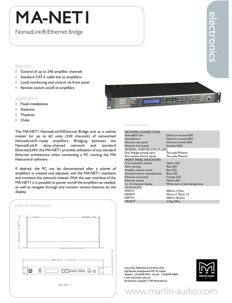
Martin Audio MA NETCONTROL User manual

The Martin Experience
MA-NET1 & MA Netcontrol
User’s Guide
All material © 2007. Martin Audio Ltd. Subject to change without notice.

Operations Guide-
MA-Net1 - Nomadlink/Ethernet Bridge
MA Netcontrol - Network Control and Monitoring Software

2
Contents
1Warnings 4
2 Introduction 5
2.1 Hardware - MA-NET1 Nomadlink/Ethernet Bridge 5
2.1.1 Mains connection 6
2.1.2 Conformity 6
2.2 Software – MA Netcontrol 7
3 Installing the MA Netcontrol Application 7
3.1 Computer system requirements 7
3.2 Software installation 8
3.3 Software updates 8
3.4 Uninstalling MA Netcontrol 8
4 Connecting your PC to NomadLink 8
4.1 Determining preferred connection type 8
4.1.1 Peer-to-peer connection 8
4.1.2 LAN connection (wired or wireless) 8
4.2 Establishing a peer-to-peer connection 9
4.2.1 Physical connection 9
4.3TCP/IPsetup 9
4.4 Establishing a wired or wireless LAN connection 11
4.5 Multiple subnets without a DHCP server 11
4.6 Maximum cable lengths 11
5 Quick Guide to Basic Functions 11
5.1 Introduction 11
5.2 Uploading Subnet(s) 11
5.2.1 No Subnets found fault 12
5.3 Toolbars overview 14
5.4 Basic Operating and Editing functions 15
5.4.1 Basic operations 15
5.4.2 Lock mode 16
5.4.3 Basic Editing: Creating Channel Groups 16
5.4.4 Naming (or re-naming) Devices, Channels and Groups 16
5.4.5 Saving the configuration file 17
5.4.6 Opening a saved system configuration file 17
5.4.7 Normal operation with devices matched and synchronized 17
5.4.8 Reconnect to a subnet 18
6 Reference section 18
6.1 Introduction 18
6.2 Offline and Online states 18
6.2.1 Selecting Online and Offline states 18
6.2.2 Functions allowed in Offline and Online states 18
6.3 Operate and Edit modes 18
6.3.1 Overview 18
6.3.2 Selecting Operate and Edit modes 19
6.3.3 Functions allowed in different mode and state combinations 19
6.4 Device View 19
6.4.1 Overview 19
6.4.2 Device View columns 20
6.4.3 Editing Functions in Device View 21
6.4.3.1 Overview 21
6.4.3.2 Add Device 21
6.4.3.3 Insert Device 21
6.4.3.4 Replace Device 21
6.4.3.5 Copy, Paste, and Paste to subnet 21

3
6.4.4 Matching to the physical subnet 22
6.4.5 Device Sorting 22
6.5 Channels View 22
6.5.1 Overview 22
6.5.2 Forming Channel Groups 22
6.6 Group View 23
6.6.1 Overview 23
6.6.2 Group View buttons and functions 23
6.6.3 Group View fault and warning indicators 24
6.6.4 Channel faults and warnings 24
6.6.5 Group and Subnet warning and fault icons 25
6.6.6 Level meters and clip LEDs 25
6.7 Details View 25
6.7.1 Overview 25
6.7.2 Subnet details 26
6.7.3 Device details 27
6.8 Tree View 28
6.8.1 Overview 28
6.8.2 Functionality 29
6.9 Locking Functions 29
6.9.1 Overview 29
6.9.2 Selecting Lock mode 29
6.9.3 Locking and unlocking 29
6.9.4 Password protection 29
6.9.5 Keep lock state 29
7 MA-NET1 warranty 30
8 Martin Audio contact details 30
9 Copyright statement 30

4
1 Warnings
The lightning symbol within a triangle is intended to alert the user to the presence of un-insulated
“dangerous voltage” within the amplifier’s enclosure that may be of sufficient magnitude to constitute a risk of
electric shock to humans.
The exclamation point within a triangle is intended to alert the user to presence of important
operating and service instructions in the literature accompanying the product.
To reduce risk of fire or electric shock, do not expose this apparatus to rain or moisture.
To reduce the risk of fire or electric shock, do not remove screws. No user-serviceable
parts inside. Refer servicing to qualified service personnel.
1. Keep this manual for future reference.
2. Heed all warnings.
3. Follow all instructions.
4. Do not use this unit near water.
5. Do not spill water or other liquids into or on the unit. Do not operate the amplifier while wet or
standing in liquid.
6. Clean only with dry cloth.
7. Do not block the air intake or exhaust ports. Install the unit in accordance with the instructions.
8. Do not operate the amplifier near heat producing devices such as radiators, heat registers, stoves or
other apparatus that produce heat. Always operate the unit with the chassis ground wire connected
to the electrical safety earth. Do not defeat the safety purpose of a grounding-type plug. A grounding
type plug has two pins and a third grounding prong. The third prong is provided for your safety. If the
provided plug does not fit into your outlet, consult an electrician for replacement of the obsolete
outlet.
9. Connect only to AC power outlets rated 100-120 V or 200-240 V, 50-60 Hz.
10. Do not use this amplifier if the power cord is broken or frayed. Protect the power cord from being
walked upon or pinched particularly at the plugs and the point where it exits from the apparatus.
11. Only use accessories specified by the manufacturer.
12. The unit is intended to use in a 19” rack. Follow the mounting instructions. When a rack on wheels is
used, use caution when moving the loaded rack to avoid injury from tipping over.
13. Unplug this apparatus during lightning storms or when unused for long periods of time.
14. Do not connect an amplifier output in parallel or series with any other amplifier’s output. Do not
connect the amplifier output to any other voltage source, such as battery, mains source, or power
supply, regardless of whether the amplifier is turned on or off.
15. Do not run the output of any amplifier back into another channel’s input.
16. Refer all servicing to qualified service personnel. Servicing is required when the apparatus has been
damaged in any way such as:
Power-supply cord or plug is damaged.
Liquid has been spilled into the unit
An object has fallen into the unit
The unit has been exposed to rain or moisture
The unit does not operate normally
The unit was dropped or the enclosure is damaged
17. Do not remove top or bottom covers. Removal of the covers will expose hazardous voltages. There
are no user serviceable parts inside and removal may void the warranty.
18. An experienced user shall always supervise this professional audio equipment, especially if
inexperienced adults or minors are using the equipment.
19. The mains plug is used as the disconnect device and shall remain readily operable. If mounted in a
19" rack causing the mains plug not being readily operable, the mains plug for the entire rack must
be readily operable.
20. The US National Differencescl.16.3 requires that NomadLinknetwork cables must be flame rated VW-1.

5
2 Introduction
2.1 Hardware - MA-NET1
The MA-NET1 NomadLink/Ethernet Bridge acts as a subnet master for up to 60 units of networked
NomadLink-ready amplifiers. Bridging between the NomadLink daisy-chained network and standard
Ethernet/LAN, the MA-NET1 provides utilization of any standard Ethernet architecture when connecting a PC
running the MA Netcontrol software.
If desired, the PC can be disconnected after a subnet of amplifiers is created and adjusted, and the MA-
NET1 maintains and monitors the network instead. With the user interface of the MA-NET1 it is possible to
power on/off the amplifiers as needed, as well as navigate through and monitor various features on the
display.
Key Features
Bridging the control and monitoring network in between Ethernet and NomadLink
Connecting PC to MA-NET1 and controlling subnet of up to 60 amplifiers (240 channels)
Direct access to Power on/off subnet of amplifiers
Monitoring and displaying faults and warnings sent from amplifiers
Voltage sensing General Purpose Input
Contact closure sensing General Purpose Inputs
1U metal chassis with bright 2x16 character white-on-blue display
Auto sensing PSU
Specifications

6
Rear panel detail
2.1.1 Mains connection
To reduce the risk of fire or electrical shock, do not expose this apparatus to rain or moisture and
objectfilled with liquids such as vases, should not be placed on the apparatus.
This apparatus must be earthed. Use a three wire grounding type line cord like the one supplied with
the product.
Be advised that different operating voltages require the use of different types of line cord and
attachment plugs. Check the voltage in your area and use the correct type.
This equipment should be installed near the socket outlet and disconnection of the device should be
easily accessible.
To completely disconnect from AC mains, disconnect the power supply cord from the AC receptacle.
The mains plug is used as the disconnect device and shall remain readily accessible. If mounted in a
19” rack causing the mains
plug not to be easily accessible, then the mains plug for the entire rack must be readily accessible.
Do not install in a confined space.
Do not open the unit - risk of electric shock inside.
Caution: You are cautioned that any change or modifications not expressly approved in this manual could
void your authority to operate this equipment.
Service: There are no user-serviceable parts inside. All service must be performed by qualified personnel.
2.1.2 Conformity
This equipment has been tested and found to comply with the limits for a Class B Digital device, pursuant to
part 15 of the FCC rules. These limits are designed to provide reasonable protection against harmful
interference in residential installations.

7
This equipment generates, uses, and can radiate radio frequency energy and, if not installed and used in
accordance with the instructions, may cause harmful interference to radio communications. However, there
is no guarantee that interference will not occur in a particular installation.
If this equipment does cause harmful interference to radio or television reception, which can be determined
by turning the equipment off and on, the user is encouraged to try to correct the interference by one or more
of the following measures:
Reorient or relocate the receiving antenna.
Increase the separation between the equipment and receiver.
Connect the equipment to an outlet on a circuit different from that on which the receiver is
connected.
Consult the dealer or an experienced radio/TV technician for help.
For Users in Canada
This Class B digital apparatus complies with Canadian ICES-003.
Cet appareil numérique de la classe B est conforme à la norme NMB-003 du Canada.
2.2 Software - MA Netcontrol
MA Netcontrol is a powerful tool for monitoring and controlling Martin Audio Q-series amplifiers that are
equipped for use with the NomadLink network.
To fully realise the power and flexibility of this program, we suggest that you refer to this manual during
setup, and also keep it handy for reference until you are fully familiar with system configuration and all
operating modes.
MA Netcontrol runs on a standard Windows PC equipped with an Ethernet interface.
Working in conjunction with the MA-NET1 NomadLink/Ethernet Bridge, MA Netcontrol allows detailed
monitoring of amplifier parameters while controlling key functions such as power on/off, mute and solo.
Although it is remarkably intuitive and easy to use, MA Netcontrol is a powerful tool for monitoring and
controlling systems of any size – from a few channels in a small venue to literally thousands of channels in
the largest imaginable stadium or theme park system.
This manual is structured to serve as a setup guide and a reference. The following two sections (3 and 4) will
guide you through installation of the MA Netcontrol software program and setup of Ethernet connections to
one or more subgroups, each controlled by an MA-NET1.
Section 5 is a Quick Guide for accessing basic control and monitoring functions. Section 6 details all
operating modes, menu options, offline system configuration, and match functions, along with the various
warning and fault indications.
3 Installing the MA Netcontrol software
3.1 Computer system requirements
Operating system: Windows 2000 or Windows XP
Processor: Intel Pentium 4 or XP-compatible equivalent (Celeron M, Athlon etc.)
RAM: 512 MB minimum
Hard drive free space: 20 MB
Monitor: 800 x 600 24-bit color
Network: Ethernet 10/1 00 Mbit
Screen resolution is fixed at 96 DPI. Altering this setting will impair the operation of MA Netcontrol so is not
advised.

8
3.2 Software installation
Install the application by running the MA Netcontrol_Installer-1.2.0.exe (or later) installer.
Follow the instructions as shown in the installation wizard.
The application installs all necessary components needed to run MA Netcontrol. A shortcut for quick access
to MA Netcontrol will be placed on your desktop.
3.3 Software updates
If you have a previous version of MA Netcontrol already installed, the MA Netcontrol installer file will
automatically upgrade your software by overwriting the older version.
Note: If the software needs to be reinstalled for any reason, it is best to always reinstall the latest version
to maintain full compatibility with any existing configuration files.
3.4 Uninstalling MA Netcontrol
Should you wish to uninstall the software for any reason, simply locate the MA Netcontrol program folder and
select the Uninstall option.
4 Connecting your PC to Nomadlink
4.1 Determining preferred connection type
You may connect your MA Netcontrol host computer to the NomadLink subnet(s) using either a direct (peer
to-peer) connection, or via a LAN (Local Area Network).
A LAN requires you to insert a router or network switch, with or without wireless (WiFi) capability.
Either a peer-to-peer or a LAN connection will work with a single MA-NET1 (one subnet); a LAN is normally
required for connection to more than one MA-NET1 (multiple subnets).
4.1.1 Peer-to-peer connection
In this configuration, a dedicated TCP/IP connection is made directly to the MA-NET1 using only an Ethernet
cable. This type of connection may be preferable in these applications:
Temporary connections for setup or maintenance of an MA-NET1 which otherwise is used as a
stand-alone unit (operation via front-panel or GPI (General Purpose Input).
Permanent connection to a computer dedicated to the MA Netcontrol application.
In this configuration, a dedicated TCP/IP connection is made directly to the MA-NET1. A peer-to-peer
connection provides maximum security as no other network devices are inserted between the computer and
the MA-NET1.
Note: If a dedicated connection is established, no other network connections will be available through the
assigned Ethernet port. However, if the computer also has multiple Ethernet ports or a wireless LAN
connection, these remain available for other uses such as Internet access.
4.1.2 LAN connection (wired or wireless)
A LAN connection is required if the system configuration requires more than one subnet, as each subnet is
controlled by a dedicated MA-NET1.
A LAN connection may be preferred in some applications even if only one subnet is required. If the host
computer is needed for Internet access via the Ethernet port, or for controlling other networked devices, a
LAN connection avoids any need to manually reset the TCP/IP configuration when switching from MA
Netcontrol to another application.
If the network router offers DHCP assignment (now common even in inexpensive models), then the MA-
NET1 can be set to automatically accept a network address from the router.

9
Note: A separate, third-party network device must be accommodated in the system to create a LAN
connection. This could raise reliability issues, particularly in touring applications. Any network
devices should be chosen with this consideration in mind.
4.2 Establishing a peer-to-peer connection
4.2.1 Physical connection
You must first establish a NomadLink subnet before connecting your MA Netcontrol host computer.
Connect the PC to the MA-NET1 unit using an Ethernet cable. A crossover cable should be used for peer-to-
peer connections; however, many newer PCs will allow peer-to-peer connection using a standard (“straight”)
Ethernet cable. See Figure 1.
Note: Two Ethernet ports are provided on the MA-NET1: one on the front-panel and one on the rear-panel.
(The front-panel port is primarily for temporary setup and service use.) However, only one PC
running MA Netcontrol may be connected to each subnet (MA-NET1) at a time.
Figure 1
4.3 TCP/IP setup
To establish direct (peer-to-peer) communication between the MA Netcontrol host PC and the MA-NET1, you
first must set the TCP/IP address in your computer.
The MA-NET1 has following default address:
IP: 192.168.1.166
Subnet mask: 255.255.255.0
Gateway: 0.0.0.0
The PC must be set manually to a compatible address, such as the following.
IP: 192.168.1.100
Subnet mask: 255.255.255.0
Gateway: 0.0.0.0 (leave blank)

10
To establish a connection, use the following procedure:
1. In XP Home - Go to the START menu in the lower left corner, select “Connect to” and then “Show
all connections”
In XP Professional - Go to the START menu in the left corner, select “Settings”, “Control Panel”
and then (if in classic view) “Network Connections”. If the “Control Panel” is in “Category view”
choose “Network and Internet Connections” and then “Network Connections”. (Fig 2).
2. Select “Local Area Connection”. Select “Properties” from the File menu or by right-clicking on the
selected icon. In the pop-up window, select “Internet Protocol” (TCP/IP) and hit Enter/OK. (Fig 2).
Figure 2 Figure 3
3. Select: “Use the following IP address” and enter: IP address: 192.168.1.100
4. Click in “Subnet mask” (Fig 3). The following enters automatically: 255.255.255.0
Leave Default gateway open. Do not enter any values.
5. Click on OK to set the address.
You can verify that your settings are correct by double-clicking on “Local Area Connection” and
selecting the Support tab (Fig 4).
Figure 4
6. The PC is now ready to connect to the MA-NET1. Refer to the instructions in Section 5.2.

11
4.4 Establishing a wired or wireless LAN connection
It is recommended that you make your LAN connections using a network device (hub, switch or router) that
includes a DHCP server function. This feature greatly simplifies network configuration. (For use with non-
DHCP devices, see 4.5)
Connect the host computer and one or more MA-NET1’s Bridges to the network device using standard
Ethernet cables.
To obtain an IP address automatically, each MA-NET1 must be set to “DHCP On”. This setting is accessed
via the front-panel navigation features of the MA-NET1.
The MA-NET1 automatically reboots after changing the setting. The front-panel display then shows
automatic acquisition of an IP address.
In most cases, no further configuration of the PC will be necessary. Because the default setting in Windows
is to “Obtain an IP address automatically,” the network connection will be established by the DHCP server.
However, if the PC has been previously set to obtain a specific address, you may need to access the
“Internet Protocol (TCP/IP) Properties” window and select the “Obtain an IP address automatically” option.
See Section 4.3.
4.5 Multiple subnets without a DHCP server
It is possible to create networks with multiple subnets using either a computer equipped with multiple
Ethernet cards, or with network devices requiring manual IP address setting. In these applications, each
connection must be manually set with a TCP/IP address with the last three digits in the range of 1 to 255.
Such applications are rare and therefore are not detailed here. However, standard procedures for TCP/IP
networks apply.
4.6 Maximum cable lengths
Maximum cable length allowed between the Device-Control host PC and the MA-NET1 (or LAN network
device) conforms to standard Ethernet specification of 100m.
5 Quick Guide to basic functions
5.1 Introduction
The following Section provides the basic information required to use MA Netcontrol in most common
applications. Instructions are provided for uploading amplifier data from physical subnets, performing basic
operations, monitoring faults and warnings and creating groups of amplifier channels.
5.2 Uploading Subnet(s)
After completing the previous steps (install MA Netcontrol, make connections, set TCP/IP), you are ready to
run the application.
Double click the MA Netcontrol shortcut on your Desk-top or select MA Netcontrol in the Start menu. On
opening, MA Netcontrol displays the Quick Start menu - Figure 5.
Figure 5

12
This window allows selection of an amplifier con-figuration for loading into MA Netcontrol. The choices are:
Uploading information from connected subnet(s)
Opening an already saved preset configuration file
Creating a new configuration from scratch.
If you are working offline (no physical subnet is connected), select the second or third choice to access
offline editing functions. See Section 6.4.3.
When a physical subnet is connected, you can automatically acquire data directly from the amplifiers by
selecting “Upload configuration from network”. MA Netcontrol interrogates the network interface, locating
available subnets ( MA-NET1 units) and listing them in a pop-up window as shown in Figure 6.
Figure 6
Note: As many as 60 MA-NET1 units can be detected and uploaded simultaneously into MA Netcontrol on
one host computer.
This window displays the detected MA-NET1 units along with subnet number, the number of devices
(amplifiers) connected to each subnet, and the TCP/IP address for the MA-NET1.
Select the subnets you want to upload and click on the Upload button.
Note: All detected subnets are selected by default. Deselect any you do not wish to upload by clicking in
the check box. (In earlier software versions without a check box, simply click somewhere in the row.)
MA Netcontrol uploads information from the subnet. It automatically generates lists and default groups for the
various display views ready to enable immediate operation.
Clicking on the Refresh button re-interrogates the network after initial uploading. Use Refresh to update
subnet information when changes are made to connected subnets, or when network connection is
temporarily lost due to inadvertent physical disconnection.
5.2.1 No Subnets found fault
If MA Netcontrol does not locate any available MA-NET1s on the network, the following message appears
(Figure ):
Figure 7

13
If you are certain that subnets have been connected, this could indicate a problem with the Windows
Firewall, a physical connection, or the network configuration.
Check Windows Firewall
If this fault appears the first time you attempt to upload subnets, and your PC has Windows XP with SP2,
your connection probably has been blocked by the Windows Firewall.
When you first click on “Upload configuration from network”, a Windows pop-up asks whether you want to
continue blocking or allow network communication by MA Netcontrol. Click on “unblock.” In some cases this
pop-up window may be hidden behind the main window; however, you will see a “Windows Security Alert”
below in the system tray. Minimize the main window or click on the Windows Security Alert in the system tray
to unblock.
You can check to see if Windows Firewall is blocking MA Netcontrol by accessing the Windows Security
Center in the Control Panel (Figure 8). Set the Fire-wall to ON (recommended) and click on Windows
Firewall in Manage Security Settings. Click on the “Exceptions” tab and confirm that the MA Netcontrol
Network Application is selected as an exception.
Figure 8
Check Connections and Configurations
Check your cable connections and your TCP/IP settings at both the PC and MA-NET1.

14
5.3 Toolbars overview
MA Netcontrol is organized around a set of views accessible by selecting buttons on the main toolbar. The
different views access various configuration, operation, and monitoring functions. More detailed information
is given in the reference Section, 6.4 through 6.8. See Figure 18.
Note: Tree View and the Mode/State buttons may be dragged to any desired point in the main window. Click
and drag on the top bar (Tree View) or end bar (Mode/State buttons).
Full screen: Toggles between full screen and reduced screen view.
Tree: The Tree View is open by default on the left of the screen when opening MA Netcontrol. This
view shows the current network configuration (either as uploaded or created offline),
including all subnet groups.
Lock: Locks or unlocks MA Netcontrol. Lock can be set in the View menu to prevent or enable
either Configuration or Operation.
Device: This view shows the list of devices (amplifiers). The left side of the list (Configuration)
displays the virtually configured devices, with the power on/off switch indicated for each
device. The right side (Physical) displays the physically detected de-vices in the subnets.
Center “link” indicators between left and right show Status and Match between configured
and physical device.
Channel: This view shows all configured channels as derived from the Device list. In this view you
may add or delete groups, and assign channels to new or existing groups.
Groups: The Groups page is generated from the selections made in the Channel list. The All and
Subnet groups are automatically generated during upload from the subnet(s) and cannot be
modified. The groups view is the primary screen for monitoring status, faults and warnings,
as well as for controlling mute and solo functions.
Details: This view shows parameter details for the selected channel or device (amplifier or MA-
NET1), including DIP switch settings and performance indicators such as level and
temperature.

15
Offline: When not connected to a physical subnet, editing of an offline configuration is possible in
Edit mode. You may add devices, add groups, rename channels and devices, and set
configured DIP switches. “Operate” is not selectable in Offline state.
Online: When a configuration is created offline and subsequent connection to a physical subnet is
required, selecting Online interrogates the network and uploads amplifier information. The
type and position of available devices are compared to the configuration, and an indication
of the “Match” status can be seen in the Device view. Online mode opens by default in
“Edit”; “Operate” can be selected after the network is interrogated.
Edit: This is the default state in Offline mode. You may select between Edit and Operate in Online
mode. In both states (Offline and Online) it is possible to add devices and groups, re-name
channels and devices, and correct mismatched devices between Configuration and Physical
subnets.
Operate: When one or more subnets are connected and match to the configuration, selecting Operate
allows you to utilize the Mute, Solo and Power on/off functions. DIP switch settings are
matched in this mode when the power is turned on, and it is possible to modify the DIP
switch configurations. Other editing functions (such as adding groups or devices) are not
possible. However it is possible to rename devices, groups etc. in this mode. Any changes
during operation (e.g. a change in DIP switch settings on the amplifiers) will be indicated as
faults or warnings in the Groups and Device views.
Add Group: Available in Edit mode (both Offline and Online) when accessing the Channel view
Add Device: Available in Edit mode (both Offline and Online) when accessing the Device view.
5.4 Basic Operating and Editing functions
The logical navigation structure and user-friendly graphical interface of MA Netcontrol make all operations
both intuitive and easy to learn.
Most users will grasp basic MA Netcontrol functions in a few minutes. Nevertheless, it is suggested that all
users configure a physical NomadLink “learning system” in a shop or other non-critical situation to become
thoroughly familiar with common operating and editing features.
Note: Some operations outlined in this Section can be performed in more than one View. To simplify the
text, only the most commonly used View is given here. See the Reference Section for each View for
more details.
5.4.1 Basic operations
The following three operations are available when MA Netcontrol is in the Online state and the Operate
mode.
Power on/off
Power on/off functions for individual amplifiers are accessed in the Device view. Click the “On” button to turn
power on or off. The button illuminates to indicate the device is powered up.

16
Each MA-NET1 may be configured for sequential power-up for all connected amplifiers in the Subnet (See
the MA-NET1 Operation Manual). To access this function in MA Netcontrol:
Click on Groups in the toolbar
Click on the Details button of the Subnet module icon
Click “On” button for Configured Power. Amplifiers will power-up in sequence as programmed in the
N LB 60E for that subnet. Repeat as needed for additional subnets.
Mute
Mute functions are most easily accessible in the Group view. Click on the “Mute” button at the bottom of the
graphical module as appropriate. You may select “All” (all channels on all subnets), “Subnet” (channels in the
selected subnet only), “Group” (channels in selected group), or any individual channel. The button illuminates
to indicate mute status of the selected channel(s).
Solo
Solo functions are most easily accessed in the Group view. You may solo a Subnet, a Group, or an individual
channel by clicking on the appropriate “Solo” button at the top of the graphical module. The yellow “Solo”
button illuminates to indicate solo status of selected channel(s). All other channels show a mute indication.
Important Notes!
Mute takes precedence over Solo. A channel that has been muted, either locally or as part of a
Group cannot be soloed until it has been un-muted.
A Mute or Solo command for a Subnet will affect all devices connected to the subnet, including those
devices not in the current configuration or shown as “Unknown.”
5.4.2 Lock mode
You may lock MA Netcontrol to prevent inadvertent changes or unauthorized use. To lock MA Netcontrol,
click on the Lock icon in the toolbar.
You may select either Configuration or Operation lock modes in the View menu.
Configuration lock prohibits changes to current and saved amplifier configurations.
Operation lock blocks access to operating functions (power on/off, solo, mute) as well as prohibiting
most changes to configuration. This is essentially a “monitor only” mode. Refer to Section 6.9.1 for
details.
You may block access to the Unlock function using the Password Protect mode. Select Lock Settings from
the View menu, and then select Use Password Protection. If no password has been entered, you will be
prompted to enter one.
5.4.3 Basic Editing: Creating Channel Groups
MA Netcontrol offers a number of features for Online and Offline editing of amplifier configurations. For many
users, the most powerful editing feature will be creating channel groups. You may assign any channel from
any device to a specific group. Channel grouping is particularly useful when channels from several devices
are assigned to the same function in the system, such as supplying power to the HF drivers in a line array.
To create channel groups, choose Device view and select Edit mode. Groups may be created and edited in
either the Offline or Online state.
To add a new Group, click the “Add Group” button. Select the channels to be added to the new Group by
clicking in the box to the right of the device corresponding to that channel. You may assign the same channel
to more than one group.
To access operating functions or status indications for a group, select the Groups view. All groups and
subnets show in this view. All operations (mute, solo etc.) selected on the group module will affect all
channels in the group. Also, any fault or warning indications affecting a channel in the group will be indicated
for the group as well. For detailed information on fault and warning indications, see sections 6.6.4 and 6.6.5.
5.4.4 Naming (or re-naming) Devices, Channels and Groups Devices
You may rename devices to indicate function or physical location, e.g. “left rack 2.” To rename a device,
choose Device view and select the device and choose “Rename” from the Edit view. Alternatively, you may

17
use a slow left click, right click and choose Rename, or use the F2 key. Enter the new name for the device.
Channels
Channels may be renamed in the Channels view using the same procedures given.
Groups
After creating channel Groups, you can rename the group to indicate the function of the assigned groups,
e.g. “Left HF”. To rename a Group, choose Channel view. Place the cursor over the group to be renamed,
right-click and select “Rename.”
The new name must be limited to six characters to fit in the “label space” on the Group module
graphic in Group view.
You may use Copy and Paste functions in the Edit menu to replace the default name with a
“template” name (e.g. “Stage L, rack X, ampX”). Then simply change the numbers as needed for
each device or channel.
Renaming functions are also accessible in the Tree View.
5.4.5 Saving the configuration file
You may save your configuration as a MA Netcontrol file by selecting Save or Save As… from the File menu.
Also, a prompt window appears when you close MA Netcontrol asking if you wish to save the file, or any file
changes.
Your saved file stores all data that was uploaded from the physical subnet as well as any changes you have
made, including renaming of devices or groups.
5.4.6 Opening a saved system configuration file
To open a saved configuration, choose the “Open saved configuration” option when first booting MA
Netcontrol. When MA Netcontrol is running, choose Open from the File menu.
To match your saved configuration to a physical network, first click the “Online” button and then the
“Operate” button. MA Netcontrol will interrogate the network and attempt to match your configuration to any
connected physical network. Devices that match will show the green “Link” icon. For devices that show
match faults, see Section 6.4.2.
5.4.7 Normal operation with devices matched and synchronized
By following the Quick Guide instructions, you will be able to upload data from the network, create groups,
name groups, re-name devices, and save a configuration file.
Under normal operating conditions, all devices in Device View will show a green “Match” indicator and a
green “Status” indicator when you re-open the file and connect to the network. (Data uploaded from the
network will match the physical configuration by definition; a mismatched state will occur only if a physical
change has been made Setting the remote switch will not result in a mismatch, only DIP switches will do that.
A faulty remote switch setting will be indicated by the ON button if current power state differs from that
desired). No further manual data entry is required using this method.
For more detailed information, please consult the Reference Section. This additional information will help you
recognize and troubleshoot anomalous conditions should they occur. It also gives more detailed instructions
on how to create and edit new configuration files “from scratch” in the Offline state.

18
5.4.8 Reconnecting to a subnet
If connection to a subnet is lost (e.g. due to accidental disconnection of network cable), a Reconnect dialog
window appears (Figure 9).
Click on Reconnect to reestablish connection. If you inadvertently click Cancel, you may reopen the dialog
window by right-clicking on the subnet in Tree View and clicking on Reconnect.
Figure 9
6 Reference Section
6.1 Introduction
The MA Netcontrol interface is highly intuitive, allowing most users to learn the basic functions of the
program without studying the detailed information to follow. However, you should become familiar with the
location and general content of this information, as it may prove useful when specific issues arise or when
anomalous conditions occur.
6.2 Offline and Online states
MA Netcontrol functions in two basic states: Offline and Online. In the online state, the application is actively
connected to a physical network (one or more subnets) via Ethernet. In the Offline state, the application is
not connected to the network.
6.2.1 Selecting Online and Offline states
You may select Offline or Online states using the dedicated buttons on the toolbar. Alternatively, you may
select the desired state in the Network menu, or by using function keys F7 (Go Offline) or F8 (Go Online).
6.2.2 Functions allowed in Offline and Online states
Different functions are available in the Offline and Online states, depending on whether the application is in
Edit or Operate mode. Allowed functions are given in tabular form in Section 6.3.3.
6.3 Operate and Edit modes
6.3.1 Overview
MA Netcontrol functions in two basic modes: Operate and Edit.
The Operate mode allows functional control of amplifiers on the physical network: power on/off, mute and
solo functions can be executed in real time. Operate mode is available only in the Online state.
The Edit mode is available in either the Offline or Online states. Edit mode allows all functions related
to configuring subnets; naming (or renaming) devices, channels or groups, and saving configuration files.
Operational functions (power on/off, mute, solo) are allowed in the Offline state but apply to the configured
“virtual network” only. Operational functions are not allowed in Edit mode in the Online state.

19
6.3.2 Selecting Operate and Edit modes
You may select Operate and Edit modes using the dedicated buttons on the toolbar. Alternatively, you may
select the desired mode in the Mode menu, or by using function keys F9 (Go to Edit mode) or F10 (Go to
Operate mode).
6.3.3 Functions allowed in different mode and state combinations
Editable operations Edit Mode Edit Mode Operate Mode
Offline online online
New Yes No No
Open file Yes No No----------------
Save*** Yes Yes Yes
Save as*** Yes Yes Yes---------------
Exit Yes Yes Yes
Add device Yes Yes No----------------
Reassign association,
drag n’ drop No* Yes No
Renamedevice Yes Yes Yes---------------
Delete device Yes Yes No
Copy device Yes Yes No----------------
Cutdevice Yes Yes No
Paste device Yes Yes No----------------
Insert Yes Yes No
Replace with new device Yes Yes No----------------
Insert new device Yes Yes No
Disconnect physical device No* Yes No----------------
Add to configuration No* Yes No
Renamegroup Yes Yes Yes---------------
Deletegroup Yes Yes No
Addgroup Yes Yes No----------------
Clear group Yes Yes No
Assign to group (marking) Yes Yes No----------------
DIP switches Yes Yes Yes
Rename channel Yes Yes Yes---------------
Deletesubset Yes Yes No
Reconnectsubset No Yes Yes---------------
Power Yes** Yes Yes
Mute Yes** Yes Yes---------------
Solo Yes** Yes Yes
*Not available
**Editable on devices in the configuration
***Not in Group view
6.4 Device view
6.4.1 Overview
Device View displays a list of all amplifiers (devices) included in the currently loaded configuration file. In the
Offline state, only the Configuration is shown. In the Online state, all devices uploaded from the physical
network are paired with corresponding devices in the Configuration.
Note: If the Configuration file is originally created by uploading data from the network, and if no changes
are made to either the configuration data or the physical amplifiers (e.g. changing DIP switches or position in
the subnet), then the corresponding fields for Configuration and Physical devices will be identical and
matched.
This manual suits for next models
1
Table of contents
Other Martin Audio Network Router manuals
Popular Network Router manuals by other brands

Keebox
Keebox W150NR user manual

Cayman Systems
Cayman Systems 2E-W user guide

Teldat
Teldat Connect-FW installation manual

Manson Engineering Industrial
Manson Engineering Industrial SBC-6108 user manual

Cambium Networks
Cambium Networks PTP 820 Series manual

Linksys
Linksys WRVS4400N - Small Business Wireless-N Gigabit Security... manual