Martin Door DC2500e User manual

The World’s Quietest Door Openers.
™
Quietest
Martin Door Manufacturing® Salt Lake City, Utah 84127-0437 USA www.martindoor.com Printed in the USA Copyright 2007©4/2007 AD-IM09-11
INSTRUCTION MANUAL
TM
DOOR OPENERS
ARTI
ARTI
N
N
M
M
Featuring Martin “Low Risk” Finger Shield Garage Doors
R
E
G
I
S
T
E
R
E
D
F
I
R
M
ISO 9001A8949
MARTIN DOOR MFG.
ISO 9001
Quality
Standard
See page 5 for IMPORTANT INSTALLATION, MAINTENANCE & SAFETY INSTRUCTIONS
WARNING! The back page helps you determine if your garage door is “HIGH RISK”.*
DC2500e
DC3700e
DC3700e-H
With Photo Eyes
Must be Ordered as a
UL Listed Martin Garage
Door and Opener System.
*
DC2500e-O
DC3700e-O
Without Photo Eyes*
RIndustry
Canada
F.C.C.
Certified
UL
CUS
R

MARTIN SIDE-MOUNT OPENER INSTALLATION
- May be mounted right side or left side -
WARNING! For Martin Finger Shield Garage Door Systems only.
TORSION SPRING
OPENER DOOR BRACKET
STRAIGHT AND CURVED
POWER ARM
“L” STRUT
EMERGENCY
RELEASE
TAG
EMERGENCY
RELEASE
CORD
KNOB
TOP DOOR SECTION
LIGHT
LENS
POWER
HEAD
POWER
HEAD
CHASSIS
“C”
BRACKETS
OPTIONAL
PUNCHED ANGLE
RAIL SUPPORT BRACKET
RAIL ASSEMBLY
BELT
TROLLEY
OPENER HEADER BRACKET
END STOP WITH CLEVIS
PIN AND COTTER RING TORSION TUBE
COPYRIGHT © 2007 MARTIN DOOR
2
TOP ROLLER BRACKET
OPENER DOOR BRACKET
3/8” X 1” SHORT NECK
CARRIAGE BOLT AND
3/8” LOCK NUT
3/8” X 1” SHORT NECK
CARRIAGE BOLT AND
2- 3/8” LOCK NUTS
TOP DOOR SECTION
OPENER HEADER
BRACKET
END STOP WITH CLEVIS
PIN AND COTTER RING
PHOTO
EYE
OPENER DOOR BRACKET
“L” STRUT (IF PROVIDED)
END
STILE
TOP ROLLER
BRACKET
OPENER DOOR BRACKET
3/8” LOCK NUTS
3/8”x1”
SHORT
NECK
CARRIAGE
BOLT
CURVED
POWER ARM
OPENER POWER ARM MUST BE FASTENED
THE OPENER DOOR BRACKETOUTSIDE
WALL
CONTROL
OR
PUSH
BUTTON
“L” STRUT

COPYRIGHT © 2007 MARTIN DOOR
MARTIN CENTER-MOUNT OPENER INSTALLATION
- May be mounted off-center for Martin Finger Shield Garage Door Systems only -
PACKET FOR OWNERS
DOOR AND OPENER
INSTRUCTION MANUALS
WARNING AND SAFETY LABEL
TORSION SPRING
OPENER DOOR BRACKET
STRAIGHT AND CURVED
POWER ARM
TORSION TUBE
EMERGENCY
RELEASE
TAG
EMERGENCY
RELEASE
CORD
KNOB
TOP DOOR SECTION
PHOTO
EYE
WALL
CONTROL
OR
PUSH
BUTTON
POWER
HEAD
CHASSIS
“C”
BRACKETS
OPTIONAL
PUNCHED ANGLE
RAIL SUPPORT BRACKET
RAIL ASSEMBLY
BELT
TROLLEY
OPENER HEADER BRACKET
END STOP WITH CLEVIS
PIN AND COTTER RING
PHOTO
EYE
LIGHT
LENS
POWER
HEAD
“L” STRUT
3
3/8” LOCK NUTS
CURVED
POWER
ARM
3/8”x1” SHORT NECK
CARRIAGE BOLT
DRILL 1/8” (3) HOLE AND FASTEN TO “L” STRUT AND DOOR SECTIONOPENER DOOR BRACKET
“L” STRUT
CURVED
POWER ARM
OPENER POWER ARM SHOULD BE FASTENED THE OPENER DOOR BRACKETINSIDE
OPENER DOOR BRACKET

COPYRIGHT © 2007 MARTIN DOOR
MARTIN GARAGE DOOR OPENER PACKAGE CONTENTS: 1 - POWER HEAD BOX, 1 - RAIL ASSEMBLY BOX
PICTORIAL DESCRIPTION
1 - POWER HEAD
1OR2-2BUTTON MINI
TRANSMITTER W/ VISOR CLIP
4 BUTTON MINI TRANSMITTER
WITH VISOR CLIP (OPTIONAL)
3 BUTTON MICRO
TRANSMITTER (OPTIONAL)
MOUNTING PLATE(OPTIONAL)
1 - PROGRAMMING TINE
2 - PHOTO EYES W / WIRE
2 - PHOTO EYES CAP FASTENERS
2 - MOUNTING BRACKETS
2 - PHOTO EYE CAPS
2 - PHOTO EYE FASTENING WHEELS
- PHOTO EYE SUN SHIELD
20 - STAPLES
4 - ROUND HEAD SCREWS
4 - PLASTIC ANCHORS
6 - CONCEALED PHOTO-EYE
WIRE RIVETS (DC3700e ONLY)
1
PICTORIAL DESCRIPTION
!
8/2001
MartinDoor Manufacturing SaltLakeCity, Utah 84127-0437 U.S.A www.martindoor.com Printed in the U.S.A. 20m Copyright 2001©AD-01IM-03
INSTRUCTION
MANUAL
MARTIN DC3700 GARAGE DOOR OPENER SYSTEM
TM
DOOR OPENERS
ARTI
ARTI
N
N
M
M
Forall Residential Garage Doors up to 12’ (3700) High.
1 - WALL CONTROL (DC3700e)
OR PUSH BUTTON (DC2500e)
2 - TAPERED HEAD SCREWS
10 - STAPLES
2 - PLASTIC ANCHORS
1 - 30’ (9144) BUNDLE OF WIRE
1- RAIL ASSEMBLY
1- STRAIGHT
POWER ARM
1 - RELEASE CORD
1 - FULL SIZE INSTRUCTION MANUAL
1 - MINI SIZE INSTRUCTION MANUAL
(PLACE IN PLASTIC PACKET ON
BACK OF MARTIN GARAGE DOOR)
2 - WARNING LABELS
1- OPENER DOOR BRACKET
1- OPENER HEADER BRACKET
1 - CURVED POWER ARM
1 - RAIL SUPPORT BRACKET
2 - FOR DC3700e - H OPENERS
2 - “C” BRACKETS
IN RAIL ASSEMBLY BOX / IN DOOR HARDWARE BOX FOR UL LISTED MARTIN GARAGE DOOR AND OPENER SYSTEMS.
IN POWER HEAD BOX
IN POWER HEAD BOX
IN POWER HEAD BOX
IN POWER HEAD BOX
EXCEPT DC3700e-O / DC2500e-O
IN POWER HEAD BOX IN POWER HEAD BOX
10’6” (3200) long Rail Assembly for doors up to 7’3” (2200) high
11’6” (3500) long Rail Assembly for doors up to 8’3” (2500) high
13’6” (4100) long Rail Assembly for doors up to 10’3” (3100) high
15’6” (4700) long Rail Assembly for doors up to 12’0”(3700) high
17’6” (5300) long Rail Assembly for doors up to 14’0”(4300) high
4-6X14mmCHASSIS
SCREWS
4 - 5/16” X 2” LAG SCREWS
4 - 3/8 X 2“ PLASTIC ANCHORS
9 - 3/8” X 1” CARRIAGE BOLTS
10 - 3/8” LOCK NUTS
1 - CLEVIS PIN, COTTER RING
4 - 1/4” X 1” THREAD FORMING
SCREWS
DC3700e
DC3700e-H
DC3700e-O
DC2500e
DC2500e-O
4
!
8/2001
MartinDoorManufacturing Salt Lake City,Utah 84127-0437U.S.A www.martindoor.comPrinted in the U.S.A. 20mCopyright 2001©AD-01IM-03
INSTRUCTION
MANUAL
MARTIN DC3700 GARAGE DOOR OPENER SYSTEM
TM
DOOROPENERS
ARTI
ARTI
N
N
M
M
ForallResidential Garage Doors up to 12’ (3700) High.
WIRELESS KEYLESS
ENTRY
KEY
SWITCH
VAULT
KEY
RELEASE
OR
MARTIN
MOUNTING PLATE
MARTIN
MARTIN
BATTERY
(#Cr2032)
MARTIN
Wall Control
Push Button
OPTIONAL
ACCESSORIES
POWERESERVE
BATTERY BACKUP
MARTIN
H = HEAVY DUTY
O = NO PHOTO EYES
Photo Eye Cap
Photo Eye Cap
Fastener
Fastening
Wheel
Photo Eye
Mounting
Bracket
Sun Shield

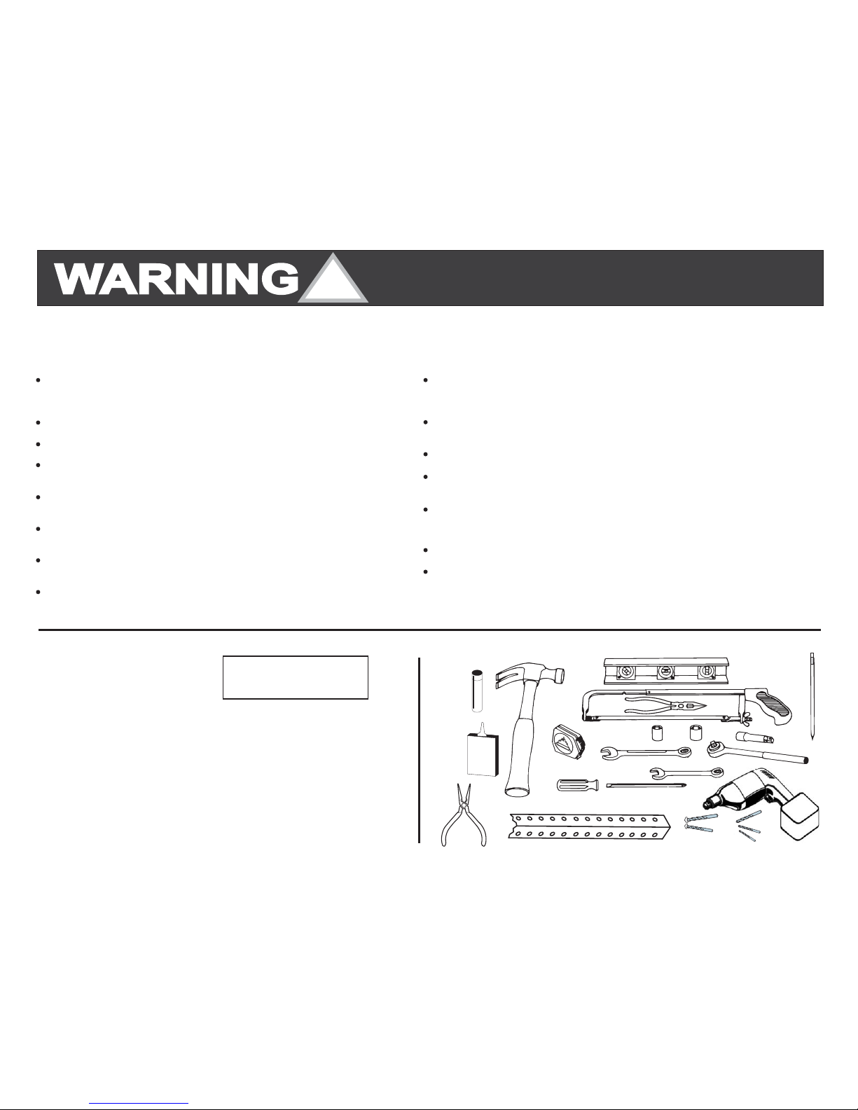
THE FOLLOWING ITEMS ARE HELPFUL TO COMPLETE A SATISFACTORY MARTIN GARAGE DOOR AND OPENER INSTALLATION:
Hammer
Level (magnetic)
Hacksaw
Wire Cutters
18’ (5.5) measuring tape
Socket wrench set for 7/16“ (11), and 9/16” (14) with 3“ (76) extension
Regular and phillips screwdriver
End wrench set for 7/16“ (11), and 9/16” (14)
10/40 motor oil lubricant
Wax lubricant (paraffin, candle, etc.)
Cordless drill with 1/8“ (3), 13/64” (5), 1/4” (6) bits
plus 1/4” and 3/8” (6 and 10) masonry bits
Step ladder (not shown)
Pencil
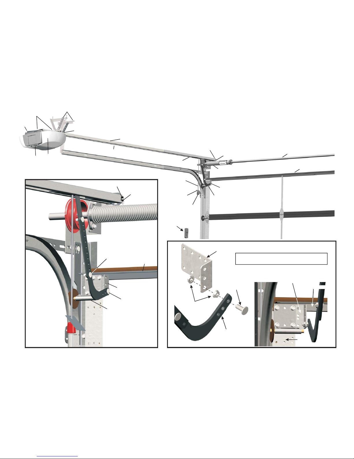
Punched angle opener hanger: 8' X 1-1/4" X 1-1/4" (2440 X 32 X 32)
Needle nose piler and wire stripper.
NOTE: Bolts, lock nuts and lag screws for fastening the punched angle are
furnished with the door opener hardware fasteners.
1.
2.
3.
4.
5.
6.
7.
8.
9.
10.
11.
12.
13.
14.
15.
2.
3.
6.
9.
WAX LUBE
10/40
MOTOR
OIL
11.
10. 4.
1.
7.
TM
GARAGE DOORS
ARTI
MN
14.
8.
6.
5.
13.
ALL MEASUREMENTS IN
PARENTHESIS ( ) ARE
MILLIMETERS IN THIS
INSTRUCTION MANUAL.
!
Do not install this opener or any other opener on "HIGH RISK" garage doors that may cause severe injury, entrapment or death!
See back page for serious injuries which may occur if “HIGH RISK” areas are left uncorrected. Martin Garage Doors are “Low Risk”.
Untrained or Negligent
Garage door
Locks
Locate
Emergency release tag
Risk of electrical shock
Entrapment and warning labels
Where possible
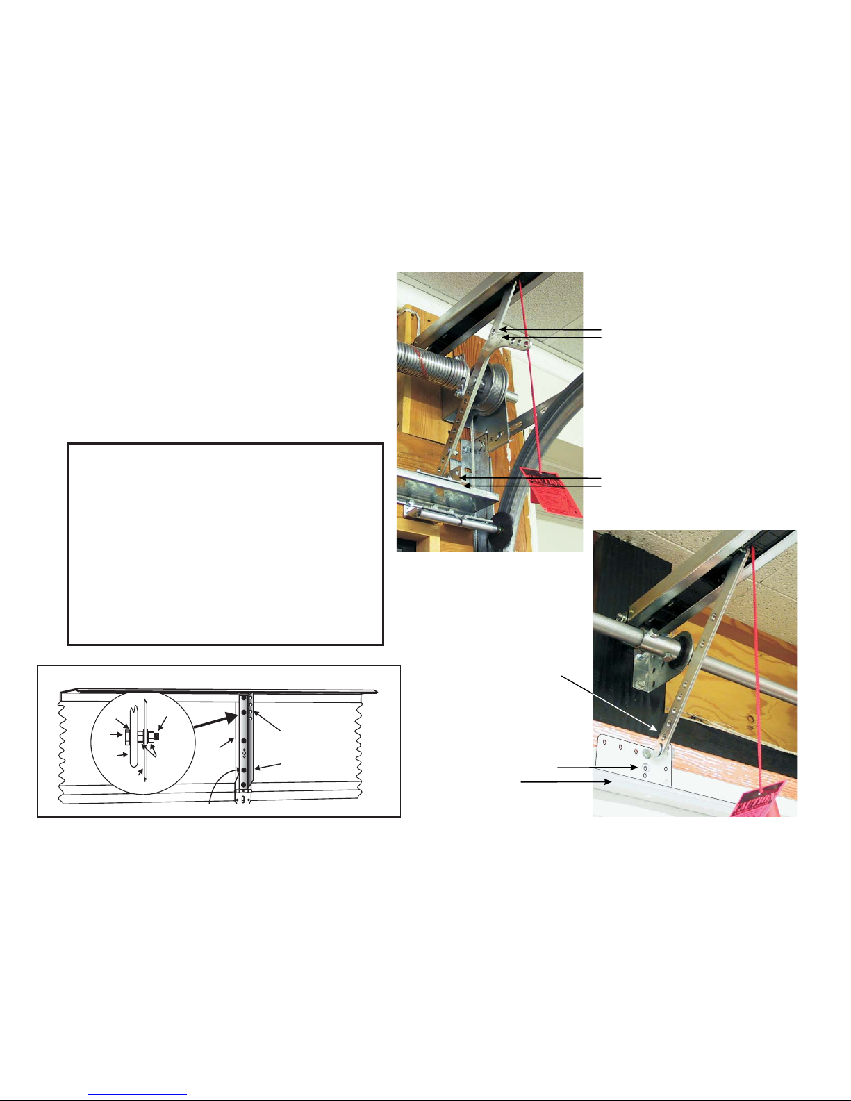
Installing, Adjusting and Servicing can be Dangerous! The
garage door springs and related parts can cause serious injury or death! IF YOU ARE
UNSURE, CALLA TRAINED MARTIN DOOR DEALER!
should be balanced and easy to open and close by hand.
should be disabled and pull down ropes should be removed.
wall control/push button within sight of door, at min. height of 5' (1520) so
small children cannot reach it, and away from all moving parts of door. See Step 8.
should be installed above knob and adjusted to about
6' (1830) above the floor.
is explained in Step10. Do not connect opener to source
of power until instructed to do so.
should be installed next to the wall control/push
button as explained in Step 14.
, install the door opener 7’ (2130) or more above the floor.
IMPORTANT INSTALLATION, MAINTENANCE & SAFETY INSTRUCTIONS
Monthly,
Always
NEVER
Do not allow children
The emergency release
Monthly
If the Safety Reverse
check the opener's down cycle safety reverse. The door must reverse when it
contacts a 1 1/2" (38) high object (or a 2X4 board laid flat) on the floor, in line with the door
opener. A closing door must also reverse if the photo eyes are interrupted. See Steps 12,13.
keep the moving door in sight and away from people and objects until it is
completely closed. NO ONE SHOULD CROSS THE PATH OF THE MOVING DOOR.
GO UNDER A STOPPED, PARTIALLY OPEN DOOR
to operate or play with the garage door opener controls. Keep all
remote controls away from children.
should only be used when garage door is in the closed position.
Weak or broken springs may cause door to fall if released in the open position, increasing
the risk of severe injury or death. Use caution when using the release with door open.
visually check the lift cables, spring assembly, hardware, etc. for wear and stability.
or any other part of the garage door and opener system do not work
properly, or if you do not understand, call a trained Martin Door Dealer.
TO REDUCE THE RISK OF SEVERE INJURY OR
DEATH, READ AND FOLLOW ALL INSTRUCTIONS
TO REDUCE THE RISK OF SEVERE INJURY OR
DEATH, READ AND FOLLOW ALL INSTRUCTIONS
SAVE THESE IMPORTANT INSTRUCTIONS
COPYRIGHT © 2007 MARTIN DOOR 5
15.

OPTIONAL POWER ARM ANGLE
FASTEN OPENER POWER
ARM DIRECTLY TO HOLE
AT SAME HEIGHT AS
TOP ROLLERS
STILE
BOLT
OIL
BOLT
HEAD
OPENER
POWER
ARM
POWER ARM
ANGLE
FASTEN TWO
NUTS TIGHT
AGAINST
POWER ARM
ANGLE
FULL HEIGHT
POWER ARM
ANGLE
(FASTEN POWER ARM ANGLE TO STILE WITH 5 1/4” X 1” THREAD FORMING SCREWS AS SHOWN.)
OPENER DOOR BRACKET GUIDELINES
ONLY Martin Finger Shield Garage Door Systems allow you
to choose center, off center or side mounting for a safer,
more attractive opener installation. See page 2 and 3
WARNING! Other brand doors are designed for center mounted
openers only. Off center or side mounted installations may result
in other brand doors binding, side shifting, twisting, and falling, as
the lift cables may detach from the cable drums.
requires 1 1/2" (38) more clearance than the
required garage door clearance.
A Martin Opener
Opener Door Bracket Exception
Martin Doors over 18'2" (5540) wide, high wind Martin Doors
and Martin wood doors over 10’2”(3100) wide use 3 1/4”(83)
wide “U” struts that fasten over top roller brackets . The opener
door bracket fastens on top of this “U” strut, at any location
with four ”(6) thread forming screws. With the door in the
closed position, f
or low clearance installations, try using
straight power arm only for fastening to the opener door
bracket.
See Figures A,B
1/4
asten straight power arm to reversed curved
power arm (curve may be cut off). The reversed curved power
arm is first fastened to opener door bracket. Fasten power
arms together at about a 45 angle for smooth opening and
closing of door. F the
°
CENTER MOUNT 8”(204)
LOW CLEARANCE
MARTIN OPENER DOOR BRACKET
FASTENED TO CENTER STILE AND
REVERSED “L” STRUT.
SIDE MOUNT 12”(305) CLEARANCE
ONE STRAIGHT POWER ARM AND
ONE REVERSED CURVED POWER ARM.
BOTH FASTENED TOGETHER AT A 45 ANGLE.°
MARTIN OPENER DOOR BRACKET FASTENED TO
3 1/4”(83) WIDE “U” STRUT
ONE STRAIGHT POWER ARM FASTENED
AT A 45 OR MORE ANGLE°
FIGURE A
FIGURE B
COPYRIGHT © 2007 MARTIN DOOR
6

OPENER HEADER
BRACKET
FIGURE 2
OPENER DOOR
BRACKET
CURVED POWER ARM
THIN VERTICAL MARK
THIN
HORIZONTAL
MARK
FIGURE 1
OPENER DOOR
BRACKET
CURVED POWER ARM
THIN VERTICAL MARK
TEMPORARY TIE
TEMPORARY TIE
5/16” X 2” LAG SCREWS
1/4” X 1” THREAD
FORMING SCREWS
1/4” X 1” THREAD
FORMING SCREWS
CENTER MOUNT
CENTER MOUNT
INSTALLATION INSTRUCTIONS FOR MARTIN GARAGE DOOR OPENER
SYSTEMS
THESE INSTRUCTIONS ARE INTENDED FOR PROFESSIONAL GARAGE DOOR OPENER
INSTALLERS. READ THROUGH THE COMPLETE INSTRUCTION MANUAL AND APPLICABLE
SUPPLEMENTAL INSTRUCTIONS BEFORE BEGINNING.
STEP 1
FASTENING THE OPENER DOOR BRACKET
Study
STEP 2
FASTENING THE OPENER HEADER BRACKET
"Opener Door Bracket Guidelines” on page 2, 3, and 6.
if the opener will be mounted to the center, off center or side of the garage door. Center
and off center mounted openers always require a “full width” top strut on the door. I
Martin Doors up to 12'2" (3700) wide may or may not require a top strut.
the opener door bracket under the top roller bracket for side mounting or on the stile
and strut for center/off center mounting. Fasten with 1/4” x 1” Thread Forming Screws.
See “Exception” on page 6.
the curved power arm to the opener door bracket with 3/8" X 1" short neck carriage bolt
and two 3/8" lock nuts as shown in the “Opener Door Bracket Guidelines” on page 2 and 3.
the curved opener power arm straight up and touch the torsion tube or spring. Make a
vertical mark , in line with the power arm. This mark will be the vertically centered
location for the opener header bracket. See Figure 1
Note: To hold the top of the curved power arm from falling down, temporarily tie it to the top of
the door bracket or strut. See Figure 1
a horizontal mark on the header
for
for
for
for
the opener header bracket to the header with two 5/16" X 2" lag screws. The vertical
and horizontal are the “centered location marks.
Decide
Fasten
Fasten
Raise
Make
11 1/2" (292)
6 1/2" (165)
5" (127)
3 1/2" (89)
Fasten
f side
mounted,
on header
2" (51) above the highest movement of the door as it
opens. See figure 2.
The following are approximate measurements above the top of a closed door to the horizontal
mark on the header:
12” (305) regular clearance track.
8" (203) low clearance track.
4 1/4" (108) low clearance track.
2 ½" (64) low clearance track.
marks ”
11 ½” (292)
Regular Clearance
TOP OF
CLOSED DOOR
3/8” X 1” SHORT NECK
CARRIAGE BOLT AND
2- 3/8” LOCK NUTS
HEADER
HEADER
REQUIRED
“FULL WIDTH”
“L” STRUT
REQUIRED
“FULL WIDTH”
“L” STRUT
COPYRIGHT © 2007 MARTIN DOOR 7

FIGURE 4
FIGURE 5
“C” BRACKET
STEP 3
STEP 4
FASTENING THE RAIL ASSEMBLY TO THE OPENER HEADER BRACKET
FASTENING THE RAIL ASSEMBLY TO THE POWER HEAD
Place
Fasten
Insert
Do not
Place
Position
the rail assembly onto the power head by lining up the sprocket assembly
opening with motor shaft. Make sure the shaft engages teeth inside assembly.
Press rail assembly down firmly onto shaft and chassis. DO NOT HAMMER!
2 "C" brackets over rail assembly and onto chassis. Flanges on "C" brackets must
fit into the four recessed areas on chassis. The rail assembly must be at a right angle to
the power head for the "C" brackets to fit properly.
6 X 14 mm chassis screws through "C" bracket holes and into chassis holes, and
tighten screws by hand with a phillips screw driver. The “C” brackets must firmly hold rail
assembly to chassis. See Figures 3, 4.
remove tape around the trolley and straight power arm until Step 9. The trolley
has been taped at the correct location so that the belt or chain position tab will activate the
position switch, and opener computer correctly. The activation begins when the opener
opens the door, for the first time.
power head on stepladder, positioning front of rail assembly on torsion tube (
for stability.
rail assembly end-stop within the opener header bracket and insert clevis pin
through the end-stop and opener header bracket. Attach the
cotter ring to the end of the clevis pin.
chassis
sprocket
power head
See Figure 3
from the closed position, See Figure 5
or on
torsion spring if side mounted) See Figure 5
See Figure 6
FIGURE 3
FIGURE 6 (Top View)
6X14mm
CHASSIS SCREW
POWER HEAD CHASSIS
RAIL ASSEMBLY
“C” BRACKETS
SPROCKET
ASSEMBLY
OPENING
POWER HEAD
6 X 14 MM CHASSIS
SCREW
POWER HEAD CHASSIS
MOTOR
SHAFT
POSITION SWITCH
OPENER HEADER BRACKET
CLEVIS PIN
COTTER RING
OPENER HEADER BRACKET
RAIL ASSEMBLY
POWER HEAD
LADDER
CURVED POWER ARM
TOP DOOR SECTION
TOP DOOR
SECTION
RAIL ASSEMBLY
TIE
END STOP
TORSION TUBE
TORSION SPRING
“TAPE AROUND TROLLEY”
(DO NOT REMOVE UNTIL
STEP 9)
“C” BRACKET
SPROCKET
OPENING
COPYRIGHT © 2007 MARTIN DOOR
8

STEP 5
MOUNT OPENER TO CEILING
Raise
Fasten
the opener power head high enough to allow the door to be
fully opened. OPEN DOOR BY HAND. Set a 1 ½" (38) high
object on the top part of the door, under the rail assembly. The
rail assembly should be square back from the opener header
bracket. See Figure 11
NOTE: If clearance is limited, the rail support bracket can be
fastened directly to the ceiling.
Twist
Slide
Bend
Fasten
rail support bracket onto rail assembly. See Figures 7
and 8
the rail support bracket forward or backward on the rail
assembly to the best location for fastening to the ceiling. See
Figure 8
tabs down to lock rail support bracket to rail assembly.
See Figure 10
optional punched angle to the rail support bracket.
See Figures 9, 10 and 11
See Figure 8
extra rail support bracket(s) to center part of rail assembly furnished for doors over
8’3”(2500) high. See Figure 11A
FIGURE 11
POWER HEAD
CHASSIS 1 1/2” (38) HIGH
OBJECT
CURVED POWER ARM
OPTIONAL PUNCHED ANGLE
RAIL ASSEMBLY
RAIL SUPPORT
BRACKET
“C” BRACKET
POWER HEAD
3/8” X 1/2” HEX HEAD BOLT
“L” STRUT
TOP DOOR SECTION
FIGURE 11A
TEMPORARY TIE
FIGURE 9
COPYRIGHT © 2007 MARTIN DOOR 9
FIGURE 8
FIGURE 7
RAIL
SUPPORT
BRACKET
TWIST
FIGURE 10
RAIL SUPPORT
BRACKET
INVISIBLE RAIL
ASSEMBLY
RAIL SUPPORT
BRACKET
RAIL ASSEMBLY
EXTRA RAIL SUPPORT BRACKET(S)
ON RAIL ASSEMBLY FURNISHED FOR
DOORS OVER 8’3”(2500) HIGH.
RAIL ASSEMBLY
OPTIONAL
PUNCHED ANGLE
POWER HEAD
RAIL SUPPORT BRACKET
5/16” X 2” LAG SCREW
OPTIONAL PUNCHED ANGLE
5/16” X 2” LAG SCREW
3/8” X 1/2” HEX HEAD BOLT
3/8” X 1/2” HEX
HEAD BOLT
3/8” LOCK NUT
RAIL ASSEMBLY
RAIL ASSEMBLY
RAIL
SUPPORT
BRACKET
TWIST Tab
Tab
Tab
Tab
Tab
Tab

RIGHT LIGHT LENS
FIGURE 12A
STEP 6
LIGHT BULBS AND LIGHT LENSES
STEP 7
Twist
Position
light bulb(s) (not included into light bulb sockets.
light lens tabs with corresponding slots in power head and chassis and snap
into place. Two screws are also furnished to fasten bottom part of DC3700e light lenses
ee Figure 12A or 12B
), maximum 60W,
.
S
PHOTO EYES SAFETY SYSTEM
For Martin DC2500e, DC3700e, DC3700e-H
Do not attempt to install Martin DC2500e-O, DC3700e-O (no
photo-eye openers), on any door except the approved, U.L. Listed Martin garage door
and opener system. Attempting to do so will void the U.L. Listing and warranty of the
opener.
Connecting Wires to Photo Eye:
Remove
Open
Push
Place
Mounting the Photo Eyes directly to Wall:
Locate
Using
Repeat
Mounting the Photo Eyes to Brackets:
Locate
Using
Attach
Align
Photo
Slightly
Tighten
about 1/2”(13) of insulation from the ends of the white and black striped photo eye wiring.
the cover flap in the bottom of the photo eye.
wire ends directly into terminal holes. To remove wiring, depress the terminal “tabs” and pull
wiring out. See
the wires in the slot on the right side of the cover flap and close. See
the mounting position 3” to 5” (76 to 127) above the floor for maximum protection.
the round-head screws, secure the photo eye to the wall. See
for the other photo eye. Use shims to align. See page 21
the mounting position 3” to 5” (76 to 127) above the floor. Brackets can be mounted in any
position as long as photo eye beam will have a clear path from one side of door to the other side. Do
not touch vertical tracks because they move as door opens and closes.
the round-head screws provided, fasten the bracket to the wall. See
the photo eye cap and the photo eye cap fastener to the bracket. Attach the photo eye to the
bracket with the fastening wheel. See
photo eyes, so they face each other before tightening fastening wheels. See
eyes maintain an invisible, unbroken beam between each other. When the photo eyes are
connected to the power head and the power is on, the green light on the transmitter photo eye will
illuminate. When the photo eyes are aligned, the red light on the receiver photo eye will illuminate.
loosen the fastening wheel on each photo eye. Rotate the photo eye in the photo eye cap or
slide it in the adjustment area of the bracket until eyes are aligned and the red light on the receiver
photo eye illuminates. See
the transmitter fastening wheel only when you are sure the photo eyes are center point
aligned. See page 21
WARNING: RISK OF ENTRAPMENT.
FIGURE 13
FIGURE 13
FIGURE 14
FIGURE 15
FIGURE 15
FIGURE 33
FIGURE 33 and page 21
CHASSIS
LIGHT BULB
LIGHT BULB
SOCKET
LIGHT BULB
LEFT
LIGHT LENS POWER
HEAD
FIGURE 13
FIGURE 14
LIGHT BULB
LIGHT
LENS
CHAIN RAIL
ASSEMBLY ONLY
POWER HEAD
FIGURE 12B
DC3700e
DC2500e
BELT RAIL
ASSEMBLY ONLY
COPYRIGHT © 2007 MARTIN DOOR
SLOT
TAB
TAB
SLOT
SLOT
TAB
SLOT
TAB
TAB
CHASSIS
SLOT
TAB
SLOT
Cover Flap
Terminal / Tabs
Wirings to Powerhead
Fastening
Wheel
Lens
Green or Red Light
Terminal Holes
(Receiver or
Transmitter Mark)
To Terminal 1
To Terminal 2
TX or RX
3” to 5”
(76 to 127)
from floor
Round-head
Screw
10
Photo Eye Cap
Photo Eye Cap
Fastener
Fastening Wheel
Photo Eye
Round-Head Screw
Jamb
Mounting Bracket
FIGURE 15
Sun Shield Should only be Installed on Receiver

3
4
MARTIN
FIGURE 17
STEP 7*** CONTINUED***
See Figure 17
CONNECTING WIRES TO POWER HEAD
Route
Open
Route
Remove
Remove
wiring through clip on bottom of photo eye holder, then run wires along wall and ceiling to power head
chassis. Use provided staples to fasten wiring to wall, joists and/or ceiling. Do not pinch wiring.
NOTE: As an alternative, the wiring can be routed along the top of the rail assembly, or along the outside of the
garage door track. Be sure the wiring is routed away from all moving parts of door and rail assembly. (For
DC3700e with Martin Door applications, see concealed photo-eye wire attachment kit instructions).
the control panel cover by gently pulling on the 2 tabs, allowing the cover to hang open. To remove, pull
carefully on the cover corner near one of the hinges. Do not twist cover or hinges may break. See Figure 23
wires through wire guide at top of power head chassis into terminal area of control panel. Separate double
wire from each photo eye into two single wires: 1) the white wire and 2) the black striped wire. See Figure 17
about 1/2" (13) of insulation from the end of each of the four single wires. Twist the white
wire ends together and twist the black striped wire ends together. Insert twisted white wire ends
firmly into terminal hole #1 by pushing directly into hole. If wires are difficult to insert, a screwdriver
may be used to depress the terminal tab while inserting the wires. To remove wiring, depress terminal
tab again and pull wiring out. Repeat procedure for the twisted black striped wire ends, except insert
them into terminal hole #2.
about 1/2" (13) of insulation from the end of each wire. Insert white wire end firmly into terminal hole #3.
Insert black striped wire end into terminal #4.
STEP 8
WALL CONTROL / PUSH BUTTON
FASTENING THE WALL CONTROL:
Attach
Locate
Mark
CONNECTING WIRES:
Route
Route
The wall control/push button will allow you to control your garage door from inside the garage. It
must be mounted within sight of the garage door, clear of all moving garage door parts or any
associated parts, at least 5’ (1520) above the floor, out of children's reach. The wall control/push
button should only be used when the door area is free of people or any obstructions.
wiring to back of wall control. White wire end attaches to terminal #3 screw; black striped wire end
attaches to terminal #4 screw.
where top mounting screw will go. Mark location on wall. Drill 1/16" (1.5) pilot hole into wall.
Fasten top screw into wall with screw head out from wall about 1/8” (3). Fasten wall control into top
slot hole by pushing down firmly onto screw head. For drywall, concrete, etc., drill 3/16” (5) pilot hole for
anchors. See Figure 18
and drill 1/16"(1.5) pilot hole through bottom screw hole. Insert screw through bottom hole from the front,
and tighten screw. Route wiring from behind through one of the recessed cutouts. Avoid pinching the wires.
wiring through cutout, along wall and ceiling, to opener power head chassis. Use provided staples to secure
wiring. Do not pinch wiring.
wiring through wire guide of chassis to terminal area of control panel. See Figure 17
To remove wiring, depress tab and pull out wiring. Multiple wall
controls may be installed, parallel or series, if wires are properly connected to terminals 3 and 4 as explained.
STRUT
PHOTO EYE
WIRING
RAIL ASSEMBLY
WIRE
GUIDE
TERMINAL
AREA CONTROL PANEL
WIRE
GUIDE
POWER HEAD
CHASSIS
TERMINAL
HOLES
TERMINAL TABS
TERMINAL
NUMBERS
FIGURE 18
SCREW
HEAD
WALL CONTROL
SCREW
WHITE
WIRE
BLACK
STRIPED
WIRE
BOTTOM
SCREW
HOLE
POWER HEAD
FIGURE 17 - CLOSE-UP
PUSH
BUTTON
COPYRIGHT © 2007 MARTIN DOOR 11
DC2500e
DC3700e

FIGURE 19
STEP 9
FASTENING POWER ARMS
Close
Remove
Pull
Position
Fasten
Pull
Always
Do Not Use the Emergency Release Cord And Knob To
Pull Door Open Or Closed.
the garage door by hand.
tape from rail assembly holding straight power
arm and allow it to hang freely. See Figure 19
the emergency release cord trolley (A
red square dot will appear next to the underside red catch)
Slide trolley to about 12" (305) from the opener header
bracket. See Figure 20
straight power arm and curved power arm so at
least two sets of holes line up.
arms together with 3/8" X 1" short neck carriage
bolts and 3/8" lock nuts. Remove Temporary Tie.
See Figures 19 and 20
the emergency release cord to activate trolley(The red
dot next to the underside red catch will disappear) Raise
door by hand until trolley locks with belt or chain connector
inside rail assembly. Pulling down on the emergency
release cord with the attached knob connects or
disconnects the trolley to the connector on the chain or
belt. See Figure 21
close the door before releasing the trolley from the
connector. The emergency release tag must be installed
above the red knob and adjusted to about 6' (1830) above
the floor. See Figure 20
to disconnect
.
.
FIGURE 20
FIGURE 21 RAIL ASSEMBLY
EMERGENCY RELEASE CORD
PULL DOWN
RED KNOB
PULL DOWN TO ENGAGE(RED SQUARE DOT WILL DISAPPEAR)
PULL DOWN TO DISENGAGE(RED SQUARE DOT WILL APPEAR)
EMERGENCY RELEASE CORD
RED KNOB
RAIL ASSEMBLY
RAIL ASSEMBLY
REMOVE TAPE
TROLLEY
TROLLEY
STRAIGHT
POWER
ARM
CURVED
POWER
ARM
STRAIGHT AND CURVED
POWER ARM
TORSION TUBE
EMERGENCY
RELEASE
TAG
OPENER
DOOR
BRACKET
OPENER
DOOR
BRACKET
3/8” X 1” SHORT NECK CARRIAGE BOLT
3/8” LOCK NUT
TEMPORARY TIE
12” (305)
MINIMUM
COPYRIGHT © 2007 MARTIN DOOR
12
RED SQUARE DOT
“L” STRUT
RED SQUARE DOT
“L” STRUT
RED KNOB
RED SQUARE DOT

STEP 10
STEP 11
CONNECT OPENER TO POWER
CORD AND PLUG
WARNING!
Plug
OPTIONAL PERMANENT WIRING: (If required by your local electrical code)
WARNING!
Disconnect
Remove
Connect
MARTIN “SMART COMPUTER” CONTROL PANEL
Open
To reduce the risk of electric shock, your opener is provided with an insulated
power cord with a 3-prong grounding plug. The power cord permits easy
connection to and disconnection from an electrical outlet. The power cord must be
plugged-in to a standard grounded outlet. If there is no outlet available at the
location, you must have a qualified electrician install an approved-grounded outlet
at the proper location.
To help prevent electrocution or fire, etc., the installation and wiring and
outlet must be done in accordance with local electrical and building codes. DO NOT
use an extension cord. DO NOT use a 3-prong to 2-prong plug adapter. DO NOT
modify or cut off the grounding pin on the plug.
the power cord into a properly grounded outlet. The #8 LED on the opener
control panel will illuminate, showing that the power is on. See Figure 23
Contact a qualified electrician to run the necessary wiring to your
opener and to perform the electrical connections.
the power at the circuit breaker.
the Power Head Housing. Unsnap the power cord strain relief cover by
disengaging the tabs. Cut the power cord within 6" (152) of the terminal block.
Replace the strain relief cover by snapping tabs back into place. Knock out conduit
hole, and bring in the permanent wiring and conduit. Secure conduit to chassis.
Attach wiring using suitable wire nuts (not provided). Reinstall power head housing.
power at the breaker. The #8 LED on the opener control panel will
illuminate, showing that the power is on. See Figure 22
control panel cover by gently pulling on the 2 tabs. Do not twist cover or
hinges may break. See Figure 23
The 3 Control Panel Buttons are labeled "P", "+", and "-”. The circular display
contains 8 numbered LED’s. See Figure 24
NOTE: When setting the adjustments, face the garage door while looking up at the
control panel. It is easier to program if control panel cover is removed.
The LED’s show useful information regarding the opener’s normal use as well as
Fault Finding. See Figure 24 and page 23
STRUT
FIGURE 22 OPTIONAL PERMANENT WIRING
FIGURE 24 MARTIN “SMART COMPUTER” CONTROL PANEL
CONDUIT
GROUND (GREEN)
HOT (BLACK)
NEUTRAL (WHITE)
TERMINAL BLOCK
CONDUIT
NUT
STRAIN RELIEF
COVER
PERMANENT
WIRING
POWER
HEAD
HOUSING
CHASSIS
FIGURE 23
CONTROL PANEL COVER
CONTROL PANEL
BUTTONS
LED’S
GROUNDED OUTLET
POWER CORD
COPYRIGHT © 2007 MARTIN DOOR 13
TAB
SCREW
SCREW
CIRCULAR LED DISPLAY CONTROL PANEL BUTTONS

***STEP 11 CONTINUED***
SETTING THE ADJUSTMENTS
Programs “A”, “B” and “C” must be followed precisly. Do not short cut the
programming process or the opener will soon become very erratic. If this happens,
follow “Clear Programmed Settings From Computer” on page 15 and start over again
by following Step 11 correctly.
Important:
Press
Press
Before beginning
This program will learn open and close travel limits and the first transmitter code.
Press
Note: The LEDs will blink while pressing the “+” and “-” buttons.
While
This program will learn the open and close weight of the door plus 15 lbs (7).
Press
Press
This program will memorize all settings.
Press
Press
Example of Programming Change:
, confirm that the garage door is the closed position, the trolley is
connected to the belt connector, and the #8 LED is illuminated showing that the power is on.
the “P” button for 3 seconds. The LEDs #8, #1, #2 should illuminate. See FIGURE 26
LEDs #6, #5, #4 should illuminate. See Figure 27
See Figure 27 LEDs #6 and #8 should illuminate, #7 should be blinking. See Figure 28
LED #7 is blinking, press and hold the desired button on the transmitter. When the
LED #7 blinks rapidly, release the transmitter button. The opener has now learned the
particular code of this transmitter (for additional transmitter programming see Figures 39,
39A, 39B). Press and release the "P" button. This stores the code in memory. As the LEDs
will fade out in a circular pattern the operational mode LEDs #4 and #8 should illuminate.
and release the "+" button. The door should open to its programed position.
and release the "-" button. The door should close to its programed position.
and release the transmitter button. The door should open to its programed position.
and release the transmitter button. The door should close to its programed position.
If the close limit needs to be changed, follow “A”
program, except press “P” button twice to bypass the open limit setting. After close limit
setting is completed, press “P” button twice to bypass transmitter code learning. LEDs #4
and #8 should illuminate. Complete “B” and “C” programs. End of programming.
“A” PROGRAM
“B” PROGRAM
“C” PROGRAM
END OF PROGRAMMING
Read “Note” on Page 15
and hold the "+" button until the door is in the opened position. Release this button. If
the door is not in the desired position, press the "+" button or the "-" button to move it
slightly. Once the door is in the desired position, press and release the "P" button. See
Figure 26
and hold the "-” button until the door is in the closed position. Release the button. If
the door is not in desired position, press the "+" or the "-" button to move it slightly. Do not
close door tight on floor. Once door is in desired position, press and release the "P" button.
COPYRIGHT © 2007 MARTIN DOOR
14
FIGURE 25
BEGIN PROGRAMMING
FIGURE 27
FIGURE 26
OPEN TRAVEL LIMIT
FIGURE 28
CLOSE TRAVEL LIMIT
TRANSMITTER PROGRAMMING
MARTIN

CLEAR PROGRAMMED SETTINGS FROM COMPUTER
The Door Should Be In The Closed Position
Press
Press
Press
Press
Press
Press
LED
Reprogram
and hold the “P” button 10 seconds until #2 LED is the only one
illuminated.
“-” button to cause the #1 LED to be the only one illuminated.
“P” button. #8 LED will start to blink.
“P” button. #1 LED will start to blink rapidly.
“+” button. #1 LED will illuminate.
“P” button. Various lights will illuminate on and off as the opener
computer clears and returns to original operating mode.
#8 and #4 will be illuminated.
opener computer, see STEP 11.
IMPORTANT MAINTENANCE & SAFETY INSTRUCTIONS
Monthly,
Always
NEVER
Do not allow children
RISK OF ENTRAPMENT!
check the opener's down cycle safety reverse. The door must reverse when it
contacts a 1 1/2" (38) high object (or a 2X4 board laid flat) on the floor, in line with the door
opener. A closing door must also reverse if the photo eyes are interrupted. See Steps 12,13.
keep the moving door in sight and away from people and objects until it is
completely closed. NO ONE SHOULD CROSS THE PATH OF THE MOVING DOOR.
go under a stopped, partially open door.
to operate or play with the garage door controls. Keep the remote
control away from children.
Do not attempt to install Martin DC2500e-O, DC3700e-O (no
photo-eye openers), on any door except the approved, U.L. Listed Martin garage door and
opener system. Attempting to do so will void the U.L. Listing and warranty of the opener.
SAVE THESE IMPORTANT INSTRUCTIONS
If the Safety Reverse
The emergency release
Monthly
KEEP GARAGE DOOR PROPERLY BALANCED.
or any other part of the garage door and opener system do not work
properly, or if you do not understand, call a trained Martin Door Dealer.
should only be used when garage door is in the closed position.
Weak or broken springs may cause door to fall, if released in the open position, increasing
the risk of severe injury or death. Use caution when using the release with door open.
visually check lift cables, spring assembly, hardware, etc. for wear and stability.
See garage door owner’s manual. An
improperly balanced door increases the risk of severe injury or death. Call a trained Martin
Door Dealer to repair lift cables, spring assemblies and other hardware.
COPYRIGHT © 2007 MARTIN DOOR 15
!
TO REDUCE THE RISK OF SEVERE INJURY OR
DEATH, READ AND FOLLOW ALL INSTRUCTIONS
TO REDUCE THE RISK OF SEVERE INJURY OR
DEATH, READ AND FOLLOW ALL INSTRUCTIONS
PHOTO EYES OR NO PHOTO EYES
For DC2500e-O or DC3700e-O UL Listed Martin Door and Opener Systems
The Door Should Be In The Closed Position
Press
Press
Press
Press
Press
OR
Press
Press
LED
and hold the “P” button until #2 LED is the only one illuminated.
“+” or “-” button to cause the #8 LED to be the only one illuminated.
“P” button. #1 LED will start to blink.
“P” button. #1 LED will start to blink rapidly.
“+” button if Photo Eyes are required. #1 LED will illuminate.
“-” button if you want to return to no Photo Eyes. #1 LED will start to blink
rapidly.
.
and hold “P” button for 5 seconds to return opener to operating mode.
#8 and #4 will be illuminated.
NOTE: Each time the door is opened or closed the #5 LED illuminates
about 2 seconds as the belt tab activates the reference switch
on the power head chassis. This is a visual check regarding
computer memory retention. The “smart computer” retains memory even after a
power outage. If belt tab is missing, #7 LED (Fault Code) will start blinking. See
Page 23.

STEP 13
STEP 12
TEST DOWN REVERSAL
Place
If
TEST DOWN CYCLE PHOTO EYES REVERSAL
For Martin DC2500e, DC3700e, DC3700e-H
Photo eyes
The
Start
Faulty
a 1 1/2”(38) high object (or a 2X4 laid flat) on the floor, in
line with the door opener. When the closing door contacts the
object, it should stop, reverse, and automatically return to the
open position. See Figure 32.
the door does not reverse, disconnect the opener and follow
“Clear Programmed Settings From Computer” on page 15 and
start over again by following Step 11 correctly.
must be clean and properly aligned. Rotate photo eyes
vertically or horizontally for correct alignment. See Figure 33.
green light on the transmitter photo eye and the red light on the
receiver photo eye must illuminate or the door will not close.
See Figures 33 and 34
the door in the downward direction. Interrupt the invisible beam by waving a
solid object between the photo eyes. The Door Must Reverse! See Figure 35
photo eyes can be bypassed with constant pressure on a wall control/push
button.
NOTE: To test the Up Stop, place an object to stop the door in its upward direction.
The opener should stop when the door contacts the object.
also has a third reversal protection system, which automatically
opens the door in about 60/80 seconds if Opener Reversal System fails.
The Martin
Opener
STRUT
FIGURE 32
FIGURE 33
FIGURE 34 FIGURE 35
Finger Shield Garage Door and Opener Systems include a maintenance and
warning label on a packet fastened to the backside of the #3 door section. Inside the
packet are the owner’s garage door and opener instruction manuals. See Figure 32
safety and instruction labels are included with your opener package. These
labels and the Instruction Manual must be fastened inside your garage where they can
be easily seen by all. We recommend fastening them next to the wall control. To fasten
labels, peel off the protective backing, and press onto smooth, clean surface. Tacks or
additional adhesive may be necessary. DO NOT PAINT OVER ANY LABELS.
See Figure 32
STEP 14
APPLY LABELS TO INSIDE OF GARAGE
Martin
Important
TM
MARTIN
!
8/2001AD-01IM-03
INSTRUCTION
MANUAL
MARTIN DC3700 GARAGE DOOR OPENER SYSTEM
TM
DOOROPENERS
ARTI
ARTI
N
N
M
M
ForallResidentialGarage Doors up to 12’ (3700) High.
MARTIN FINGER SHIELD GARAGE DOOR AND OPENER SYSTEM
INSTRUCTION MANUALS AND WARNING LABEL
(FACTORY PACKAGED AND MOUNTED)
GARAGE DOOR OPENER
INSTRUCTION MANUAL
AND WARNING LABELS
1 1/2”(38) HIGH OBJECT
FOR DOOR REVERSAL TEST
WALL CONTROL
OR PUSH BUTTON
COPYRIGHT © 2007 MARTIN DOOR
16
Rotation
Adjustment
Fastening Wheel
Bracket
Horizontal
Adjustment
INVISIBLE BEAM
TRANSMITTER
GREEN LIGHT ON
SOLID OBJECT BETWEEN
PHOTO EYES
RECEIVER
RED LIGHT OFF
PATH MUST BE CLEAR
BETWEEN PHOTO EYES
RECEIVER
RED LIGHT ON
INVISIBLE BEAM
TRANSMITTER
GREEN LIGHT ON
Green or Red Light
SUNSHIELD SHOULD ONLY BE INSTALLED ON RECEIVER
SUNSHIELD

FIGURE 36
STEP 15
TRANSMITTERS
THE BATTERY:
Pry
TRANSMITTER MOUNTING CHOICES:
Transmitter
MULTIPLE TRANSMITTERS:
Each
Connect
Press
TRANSMITTER OPERATION:
Press
transmitter apart using a small coin to expose battery. The 3 Volt #CR2032 battery is
shown. Battery life can last 4 to 5 years. See Figure 36.
can be carried alone, attached to a key chain, attached to the visor clip or
attached using the optional mounting plate. See Figures 36, 37, 38.
transmitter has been factory programmed with different private security codes. For
your information there are 284 trillion different codes. 2-channel transmitters have 2
different codes. 4-channel transmitters have 4 different codes. Additional transmitters
that come with the opener or are purchased separately as accessories have their own
different codes that must be changed to match your first transmitter.
the programming tine to both transmitters. See Figures 38, 39, 39A and 39B.
and hold button on your present transmitter. Indicator light will illuminate. See
Figure 39A. While still holding the 1st transmitter button, press and hold the button on the
new or second transmitter. Code transfer will occur in approximately 2 seconds when the
indicator light will blink and then illuminate on the new transmitter. See Figure 39B
The 315 MHz transmitters are “Home Link” compatible. Follow instructions furnished in the
automobile owners manual for non-rolling code applications.
button until garage door begins to move. The indicator light on the transmitter will
illuminate. Press button at any time during travel to stop the garage door. See Figure 40
FIGURE 37
FIGURE 38
FIGURE 39
SNAP VISOR CLIP INTO SOCKET
FIGURE 39A FIGURE 39B
FCC Certified: This device complies with Part 15 of the FCC rules. Operation is subject to the following two conditions: (1) this device may not
cause harmful interference, and (2) this device must accept any interference received, including interference that may cause undesired operation.
Changes or modifications not expressly approved by the party responsible for compliance could void the user's authority to operate the equipment.
MINI
TRANSMITTER
COPYRIGHT © 2007 MARTIN DOOR 17
PRESENT
TRANSMITTER
NEW OR SECOND
TRANSMITTER
PRESENT
TRANSMITTER
NEW OR SECOND
TRANSMITTER
INDICATOR
LIGHT
MARTIN MARTIN
MARTINMARTIN
PRESENT
TRANSMITTER
NEW OR SECOND
TRANSMITTER
INDICATOR
LIGHT
MARTIN
COIN
MARTIN
TRANSMITTER
FIGURE 40
VISOR CLIP COVER
(REMOVE SMALL
COVER TO EXPOSE
VISOR CLIP SOCKET)
VISOR CLIP SOCKET
PROGRAMMING
TINE
MINI TRANSMITTER
BACK
BATTERY
(#CR2032)
MINI TRANSMITTER
FRONT
CIRCUIT BOARD
3 BUTTON MICRO
TRANSMITTER
(OPTIONAL) 4 BUTTON MINI
TRANSMITTER
(OPTIONAL)
MARTIN
SCREW
MOUNTING PLATE
(OPTIONAL MAY BE USED AS
A WALL CONTROL ETC.
)
MINI
TRANSMITTER
PROGRAMMING
TINE
PROGRAMMING
TINE
PROGRAMMING
TINE

***STEP 15
STEP 16
WALL CONTROL/PUSH BUTTON OPERATION
CONTINUED***
ANTENNA:
The
Do
not lengthen or shorten the antenna.
Press
The
Press
OPENER LIGHTS OPERATION:
Lights
Lights
315 MHz antenna wire on the back of the opener is about 13”(340) long and
can have multiple arrangements for the best distance. In a "normal installation" the
distance from the transmitter to the power head should be 50' (15000) to 150' (45000).
See Figures 41, 42.
NOTE: The distance from the transmitter to the opener power head may be reduced by
electrical interference in the area, spherical disturbances in the area, various lights
or transformers in and out of the garage, automatic sprinkler system timers,
various audible or inaudible sounds, noise, radio signals in the area, concrete,
steel or lead in and around the garage, antenna wire touching any metal. If
necessary, use plastic or string type ties to keep antenna wire away from punched
angle, etc.
The wall control button will illuminate when the wires are properly connected as explained
in Step 8.
wall control/push button until garage door begins to move. Press button at any
time during travel to stop the garage door. See Figure 43.
vacation lock-out feature on the wall control is used to lock out all remote control
transmitters. The wall control button or keyless entry system can still activate the door.
and hold vacation lock button for 2-3 seconds to activate lock-out. The wall control
button will blink continuously while lock mode is active. To unlock, press and hold vacation
lock button for 2-3 seconds. The wall control button will then return to normal illumination.
See Figure 43
NOTE: The opener will accept multiple wall controls/push buttons if the wires are properly
connected as explained in STEP 8.
will illuminate for about 4 minutes whenever opener is activated. Lights will blink if
the opener senses an obstruction. To stop lights from blinking, remove obstruction and
operate door normally.
can be turned on and off by manually pushing light switch button on the wall
control. Lights turned on manually can only be turned off by manually pushing light switch
button or by opening and closing the door. See Figure 43.
receiver
FIGURE 41
FIGURE 42
FIGURE 43
ANTENNA
WIRE
PUSH
BUTTON
(DC2500e)
COPYRIGHT © 2007 MARTIN DOOR
18
MARTIN
VACATION LOCK
BUTTON
LIGHT SWITCH
BUTTON
WALL CONTROL
BUTTON
WALL
CONTROL
(DC3700e)
DC2500e
DC3700e
ANTENNA
WIRE

FIGURE 44
STEP 17
R
STEP 18
BELT AIL ASSEMBLY TENSION ADJUSTMENT
There should be no need for adjustment
CHECKING TENSION:
Release
ADJUST THE TENSION:
Increase
Decrease
TO SHORTEN BELT ASSEMBLY UP TO 24” (610):
(See exploded view of rail assembly on Page 21)
Loosen
Remove
Slide
Measure
Disassemble
Use
Use
Fasten
Slide
Tension
Your pre-assembled Belt Assembly comes from the factory with the tension adjusted to
factory specifications. .
trolley from belt connector. The tension nut/washer should be spaced
approximately 1/16" (1.5) from the stationary end-stop arch at the
header end of the rail assembly. See Figure 45.
tension by tightening tension nut clockwise.
tension by loosening tension nut
counterclockwise.
Note: For trained Martin Garage Door Dealers: Consult factory if cut-off is more than 24”
(610) because the position tab must be kept in the proper location.
belt tension as much as possible.
screws from sprocket holder and rail end-stop.
belt and all rail assembly parts out of rail assembly from header end.
and cut off excess rail assembly (1” (25) increments only) from header end.
connector assembly to expose free ends of belt.
the same measurement as the excess rail assembly length and cut the same
amount off both free ends of the belt.
rail assembly end-stop as a guide, mark and drill two 3/16" holes on rail
assembly sides for rail assembly end-stop screws.
both ends of the belt ribs to the connector assembly.
all rail assembly parts into rail assembly from header end according to
original assembly.
the belt following STEP 17.
FIGURE 45
HEADER END OF RAIL ASSEMBLY BELT
TIGHTEN THIS DIRECTION
RAIL END-STOP
WRENCH
VIEW FROM BELOW
IMPROPER TENSION - TOO LOOSE
PROPER TENSION
RAIL END-STOP
RAIL END-STOP
RAIL ASSEMBLY
RAIL ASSEMBLY
TENSION NUT
AND WASHER
TOO MUCH
SPACE
STATIONARY
END-STOP
TENSION NUT
AND WASHER
CORRECT
SPACE IS 1/16”(1.5)
STATIONARY
END-STOP
HEADER END
HEADER END
COPYRIGHT © 2007 MARTIN DOOR 19

MARTIN POWER HEAD ASSEMBLIES
- EXPLODED VIEW -
Item Description
1. Light Lens(1 right and 1 left lens for DC3700e, 1 lens at
rear for DC2500e)
2. Wire harness assembly
3. Light socket w/ Wire Harness
4. Chassis w/ Labels
5. Connector
6. Reference Switch
7. Power Cord
8. Strain Relief Cover
9. Terminal Block
10. Logic Board (LB)
11. Wire Harness (TR to LB)
12. Transformer w/ Screws (2)
13. Motor Assembly complete with: Motor, Mounting Plate,
RPM Sensor w/ Harness, RPM Wheel, Screws (4)
14. RPM Sensor w/ Harness and Screw
15. Housing w/ Screws & Labels
16. Control Panel Cover w/ Label
17. Varistor
18. Motor Shaft Adapter (DC3700e only)
19. Modular Receiver(315 MHz)
COPYRIGHT © 2007 MARTIN DOOR
20
INSERT
RECEIVER
TOP OF
CHASSIS
19
4
15
43
3
6
7
8
9
10
13
14
17 2
11
12
3
2
14
18
6
5
1
3
4
1
3
15
DC3700e
16
1
1
15
7
DC3700e DC2500e
3
4
1
15
19
This manual suits for next models
4
Table of contents
Other Martin Door Garage Door Opener manuals