manuals.online logo
Brands
  1. Home
  2. •
  3. Brands
  4. •
  5. marutsu
  6. •
  7. Motherboard
  8. •
  9. marutsu TB67S128FTG User manual

marutsu TB67S128FTG User manual

Instruction manual
for Evaluation Board
- TB67S128FTG -
December 20th, 2018
Rev.1.0
【Outline】
The TB67S128FTG is a t o-phase bipolar stepping motor driver using a PWM
chopper. CLK-IN control system and BiCD process are adopted. Rating of 50 V
and 4.5 A is realized.
This evaluation board mounts necessary components to evaluate the IC. Each
excitation mode of full step, half step, quarter step 1/8 step, 1/16 step, and 1/32
step is possible ith PWM constant current drive. Please sense lo -noise and
lo -vibration drive of stepping motors applying the TB67S128FTG.
【Note】
In using, please be careful about the thermal condition sufficiently.
As for each control signal, please refer to the IC specification by accessing to the
belo URL.
https://toshiba.semicon-storage.com/us/product/linear/motordriver/detail.TB67S128FTG.html
Further, the application of this evaluation board is limited to the purpose of
evaluating and learning the motor control. Please do not ship them to a market.
RESET
CW CCW
Connection to evaluation board
Two-phase bipolar type
Stepping motor
Power supply
VM
(10 V to 47 V)
Reference voltage for
motor current setting
VREF (0 V to 3.6 V)
VM
GND
VREF(for Phase A Phase B)
CLK
STANDBY
ENABLE
LO0
LO1
Connection to evaluation board
VM
GND
CLK
NC
NC
NC
NC
NC
NC
NC
NC
NC
NC
NC
NC
NC
NC
DATA
STANDBY
LATCH
BANK_EN
NC
NC
NC
NC
NC
LO0
LO1
Two-phase bipolar type
Stepping motor
Power supply
VM
(10 V to 47 V)
Reference voltage for
motor current setting
VREF (0 V to 3.6 V)
VREF(for Phase A Phase B)
Setting evaluation board 1
Setting motor current
Waveform of motor current
Charge Fast
Slow
Current value of setting motor
Setting motor current
VREF
R_VREF2
R_VREF1
RS1RS2
R_VREF2
R_VREF1
Mounting
area
On this evaluation board, external components are
mounted based on ACDS mode. When uses external
sense RS resistor mode, please remove solder from short
round of RS1 and RS2. And please mount external current
sense resistor on R_RSA and R_RSB.
When uses VCC voltage for generating VREF, please add
dividing voltage resistors to mounting area of R_VREF2
and R_VREF1.
①ACDS (RS resistor less) mode: RS_SEL=Lo
GAIN_SEL=Lo :
Iout(max) = 1.56 x VREF(V)
GAIN_SEL=High:
Iout(max) = 0.78 x VREF(V)
②External sense RS resistor mode: RS_SEL=High
Iout(max) = VREF(gain) x
GAIN_SEL=Lo :VREF(gain) is 1/5.0 (typ.).
GAIN_SEL=High:VREF(gain) is 1/10.0 (typ.).
Vref(V)
RRS(Ω)
Setting evaluation board 2
Setting chopping frequency of the constant current of the motor
Waveform of motor current
Charge Fast
Slow
COSCM
Chopping frequency (fchop)
Formula of setting chopping frequency
fOSCM [MHz] = 4.0 x ROSC [kΩ](-0.8)
fchop = fOSCM / 16
COSC = 270 pF (fix)
Mounted components are as follo s;
Capacitor (OSCM=270 pF)
Resistor (ROSCM=5.1 kΩ)
ROSCM
Setting evaluation board 3
Setting motor operation
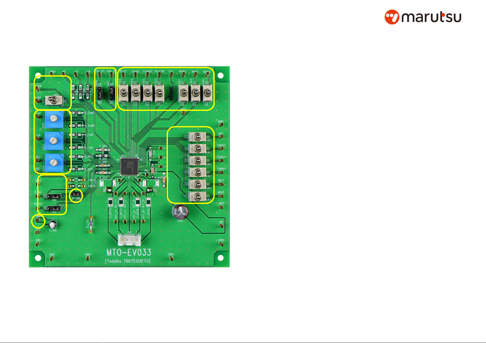
Three-position toggle s itches ((1), (5), and (6) in the left
diagram) and level select pins ((3) and (4)) for setting the
operation of the TB67S128FTG and a rotary s itch ((2) in the left
figure) for adjusting the AGC function are mounted.
In using these s itches, short-circuit the jumper of JP_VDD (i.e.
initialize) or supply 5-V voltage from the VDD pin.
【S itches of (1) and (6)】
Tilting right ard: High level
Tilting left ard: Lo level
Middle position Neutral. The input signal from the pins is valid.
【S itches of (5)】
Tilting do n ard: Lo level
Tilting up ard: High level
Middle position Neutral. The input signal from the pins is valid.
【S itch of (2)】
Four states can be selected by this rotary s itch.
Position 1: Connecting to GND.
Position 2: Connecting to GND through a resistor of 100 kΩ.
Position 3: Connecting to VDD through a resistor of 100 kΩ.
Position 4: Connecting to VDD.
【S itch of (3)】
Short to left ard: Lo level
Short to right ard: High level
Remove short pins, the input signal from the pins is valid.
【S itch of (4)】
Short to up ard: Lo level
Short to do n ard: High level
Remove short pins, the input signal from the pins is valid.
※Refer to the datasheet for information on
ho to use and set each function.
VDD pin
(1) (4)
(3)
(5)
JP_VDD
(6)
Circuit of evaluation board
Manufactured and Distributed by
Sendai Kamisugi store, Akihabara store, Akihabara store number 2, West Tokyo Office, Shizuoka Yahata store,
Hamamatsu Takabayashi store, Nagoya Otai store, Kanazawanishi interchange store, Fukui Ninomiya store,
Kyoto Teramachi store, Osaka Nipponbashi store, Hakata Gofukumachi store, marutsu online
Marutsuelec Co., Ltd.
5-2-2, Seiki Daiichi Building 7F, Sotokanda, Chiyoda-ku,
Tokyo 101-0021, Japan
Tel:+81-3-6803-0209 FAX:+81-3-6803-0213
●This product was not designed for use with devices which could cause
personal injury in the event of failure or malfunction, including devices for
use in areas including medical, military, aviation, aerospace, nuclear control,
other types of safety mechanisms, etc., or for use in devices which require a
high standard of safety. Do not use this product for such applications. This
company assumes no liability for damages which may result from use of the
product.
◆Important Note ◆

Other marutsu Motherboard manuals

marutsu TB67H452FTG User manual

marutsu

marutsu TB67H452FTG User manual

marutsu TB67H400AHG User manual

marutsu

marutsu TB67H400AHG User manual

marutsu TB67S109AFNG User manual

marutsu

marutsu TB67S109AFNG User manual

marutsu TB6605FTG User manual

marutsu

marutsu TB6605FTG User manual

Popular Motherboard manuals by other brands

ESC G41T-M user guide

ESC

ESC G41T-M user guide

DFI NB76-TC user manual

DFI

DFI NB76-TC user manual

Foxconn 661MXPlus Easy installation guide

Foxconn

Foxconn 661MXPlus Easy installation guide

Asus M4A78-VM IN SI user manual

Asus

Asus M4A78-VM IN SI user manual

Supermicro X10DRT-PS user manual

Supermicro

Supermicro X10DRT-PS user manual

Advantech PCM-3363 user manual

Advantech

Advantech PCM-3363 user manual

ASRock Industrial IMB-X1314 Settings guide

ASRock Industrial

ASRock Industrial IMB-X1314 Settings guide

MSI P45D3Neo3 Series manual

MSI

MSI P45D3Neo3 Series manual

Avalue Technology EMX-ZXEDP user manual

Avalue Technology

Avalue Technology EMX-ZXEDP user manual

ASROCK IMB-380-D user manual

ASROCK

ASROCK IMB-380-D user manual

Trinamic TMCM-1617-BB manual

Trinamic

Trinamic TMCM-1617-BB manual

Advantech PCI-6771 series user manual

Advantech

Advantech PCI-6771 series user manual

VIA Technologies VAB-950 How to connect

VIA Technologies

VIA Technologies VAB-950 How to connect

Autel MaxiIM IM508 manual

Autel

Autel MaxiIM IM508 manual

ASROCK FM2A85X Extreme4-M user manual

ASROCK

ASROCK FM2A85X Extreme4-M user manual

Xilinx Virtex-5 FPGA ML561 user guide

Xilinx

Xilinx Virtex-5 FPGA ML561 user guide

DynaGen GSC400 Series user manual

DynaGen

DynaGen GSC400 Series user manual

MSI Z97U GAMING 9 ACK instruction manual

MSI

MSI Z97U GAMING 9 ACK instruction manual

manuals.online logo
manuals.online logoBrands
  • About & Mission
  • Contact us
  • Privacy Policy
  • Terms and Conditions

Copyright 2025 Manuals.Online. All Rights Reserved.