Marvair MAR7000 Operational manual

MAR7000 1 1/2013, P/N 01757 Rev. B
Overview
The MAR7000 is a controller and sensors in a
single, aractive package that creates a exible
solution to stand-alone control challenges or
BACnet network challenges. Temperature,
humidity, and motion sensing are standard.
Flexible input and output congurations
and built-in programming ensure that a
variety of application needs can be met:
◆ Heat pump unit, with up to two
compressor stages, and with op-
tional auxiliary heat, emergency
heat, dehumidication, and/or
fan status
◆ A/C, with up to two H/C stages,
and with optional economizer,
dehumidication, and/or fan
status
Features
Interface and Function
◆ User-friendly English-language menus (no obscure numeric codes) on a 64 x
128 pixel, dot-matrix LCD display with 5 buons for data selection and entry
◆ Built-in, factory-tested libraries of congurable application control sequences
◆ Integral energy management control with deadband heating and cooling set-
points and other advanced features
◆ Schedules can easily be set uniquely by entire week (Mon.–Sun.), week-
days (Mon.–Fri.), weekend (Sat.–Sun.), individual days, and/or holidays—or
“learned” automatically via motion sensing
◆ Six On/O and independent heating and cooling setpoint periods are available
per day
◆ Three levels of password-protected access (user/operator/administrator) pre-
vent disruption of operation and conguration
◆ Integral temperature, humidity, motion, and CO2 sensor options
◆ A 72-hour power (capacitor) backup and a real-time clock for network time
synchronization or full stand-alone operation
BACnet Standards
◆ Meets or exceeds BACnet AAC specications in the ANSI/ASHRAE BACnet
Standard 135-2008
MAR7000
Thermostat/Controller
Specifications and design subject to change without notice.

MAR7000 2 1/2013, P/N 01757 Rev. B
Inputs and Outputs
◆ Three or six analog inputs for use with exter-
nal devices such as mixed air temperature, fan
status, outside air, and remote CO2
◆ Analog inputs accept industry-standard 10K
ohm thermistor sensors or dry contacts
◆ Inputs can be congured via a switch for 10K
ohm pull-up resistors (for unpowered contacts
or devices) or 0–12 VDC
◆ Input overvoltage protection (24 VAC, continu-
ous)
◆ 12-bit analog-to-digital conversion on inputs
◆ Seven NO, SPST (Form “A”) relays carry 1 A
max. per relay or 1.5 A per bank of 3 relays
(relays 1–3 and 4–6) @ 24 VAC/VDC
Connections
◆ Screw terminal blocks, wire size 14–22 AWG,
for inputs, outputs, power, and BACnet net-
work
◆ Integral peer-to-peer BACnet MS/TP LAN net-
work communications on all devices (with con-
gurable baud rate from 9600 to 76.8K baud)
◆ A four-pin EIA-485 data port on the underside
of the case enables easy temporary computer
connection to the BACnet network
◆ “E” versions add an RJ-45 jack
Installation
◆ Backplate mounts on a standard vertical 2 x
4-inch wall handy-box
◆ Two-piece design allows eld rough-in and
termination of eld wiring to the backplate
without needing the MAR7000 at the site—
permiing MAR7000s to be bulk-congured
o-site and plugged into the wired backplates
at a later time if desired.
◆ Aractive white plastic case
Supply Voltage 24 VAC (+20%/–15%), Class 2
Supply Power 13 VA (not including relays)
Connections Wire clamp type terminal
blocks; 14–22 AWG, copper
Four-pin EIA-485
Outputs NO, SPST, Form “A” relays
carry 1 A max. per relay or
a total of 1.5 A per bank of 3
relays (relays 1–3 and 4–6) @
24 VAC/VDC
External Inputs Analog 0–12 VDC (active/
passive contacts, 10K therm-
istors)
Display 64 x 128 pixel dot matrix
LCD
Case Material White ame-retardant plastic
Dimensions 5.406 x 4.9 x 1.135 inches
(138 x 125 x 29 mm)
Approvals UL 916 Energy Manage-
ment Equipment;
FCC Class B, Part 15, Sub-
part B and complies with
Canadian ICES-003 Class
B (CO2 models only: FCC
Class A, Part 15, Subpart B
and complies with Canadian
ICES-003 Class A)
Weight 0.496 lbs. (225 g) or 0.694
lbs. (314 g) for CO2 models
Humidity Sensor
Sensor Type CMOS
Range 0 to 100% RH
Accuracy @ 25°C ±2% RH (10 to 90% RH)
Response Time Less than or equal to 4 sec-
onds
Temperature Sensor
Sensor Type CMOS
Accuracy ±0.9° F oset (±0.5° C) from
40 to 104° F (4.4 to 40° C)
Operating Range 36 to 120° F (2.2 to 48.8° C)
Motion Sensor Passive infrared with 10
meter (33 feet) range (see
diagrams on the next page)
CO2 Sensor See chart on the next page
Environmental Limits
Humidity 0 to 95% RH (non-condens-
ing)
Specifications
Dimensions (assembled) in inches (millimeters)
EIA-485 data
port for quick
network access
4.9" (125)
1.135" (29)
5.406"
(138)
Terminal blocks on backplate
Tabs Location

MAR7000 3 1/2013, P/N 01757 Rev. B
55°
10 m
32.8 ft
10 m
32.8 ft
X
0°
Occupancy Sensor Detection Performance
Top View
Side View
10 m
32.8 ft
10 m
32.8 ft
0°
46.5°
Y
Motion/Occupancy Sensor
Detection Performance
55°
10 m
32.8 ft
10 m
32.8 ft
X
0°
Occupancy Sensor Detection Performance
Top View
Side View
10 m
32.8 ft
10 m
32.8 ft
0°
46.5°
Y
Applications For zones with occupied/unoccupied times
Method Non Dispersive Infrared (NDIR), with ABC
Logic
Calibration Self-calibrates over several weeks*
Typical Life of
Sensor 15 years
Measurement
Range 400 to 2000 ppm
Accuracy (at
nominal operating
temperature)
±35 ppm @ 500 ppm, ±60 ppm @ 800 ppm,
±75 ppm @ 1000 ppm, ±90 ppm @ 1200 ppm
Altitude
Correction Configurable from 0 to 32,000 feet
Pressure
Dependence 0.135 of reading per mm Hg
Temperature
Dependence 0.2% FS (full scale) per °C
Stability < 2% of FS over life of sensor
Response Time < 2 minutes for 90% step change typical
Warm Up Time < 2 minutes (operational) and 10 minutes
(maximum accuracy)
This model uses Automatic Background Calibration Logic, or
ABC Logic, a patented self-calibration technique designed to be
used in applications where concentrations will drop to outside
ambient conditions (approximately 400 ppm) at least three
times in a 14 day period, typically during unoccupied periods.
With ABC Logic enabled, the sensor will typically reach its
operational accuracy after 25 hours of continuous operation
if it was exposed to ambient reference levels of air at 400 ±10
ppm CO2. The sensor will maintain accuracy specifications with
ABC Logic enabled, given that it is at least four times in 21 days
exposed to the reference value and this reference value is the
lowest concentration to which the sensor is exposed. ABC Logic
requires continuous operation of the sensor for periods of at least
24 hours.
CO2 Sensor Specifications
Backplate for CO2 Sensor Models
(with Horizontal Terminal Blocks)
Shipping –22 to 140° F (–30 to 60° C)
Operating 34 to 125° F (1.1 to 51.6° C)*
*NOTE: CO2 models Operating range is 34 to
122° F (1.1 to 50° C)

MAR7000 4 1/2013, P/N 01757 Rev. B
Connections and Wiring
Wiring Considerations
• Because of the many connections (power,
network, inputs, outputs, and their respective
grounds or switched commons), be sure
wiring is well planned before installation of
conduit!
• Make sure that conduit for all wiring has
adequate diameter for all necessary wiring.
Using 1-inch conduit and junction boxes is
recommended! Use external junction boxes
above the ceiling or in another convenient
location as needed to make connections that
run to the MAR7000’s junction box.
• To prevent excessive voltage drop, use a
conductor size that is adequate for the wiring
length! Allow plenty of “cushion” to allow
for transient peaks during startup.
• Using multiple conductor wires for all inputs
(e.g., six conductor) and outputs (e.g., 12
conductor) is recommended. Grounds for all
the inputs can be combined on one wire.
CAUTION
To avoid damage from ground loops and
other communication issues in networked
MAR7000s, correct phasing on MS/TP
network and power connections on ALL the
networked controllers is critically important.
CAUTION
• This thermostat is for 24 VAC applications only.
Do not use on voltages over 30 VAC.
• All installation and wiring must conform to local
and national electrical and building codes.
• Use this thermostat only as described in this
manual.
Mounting
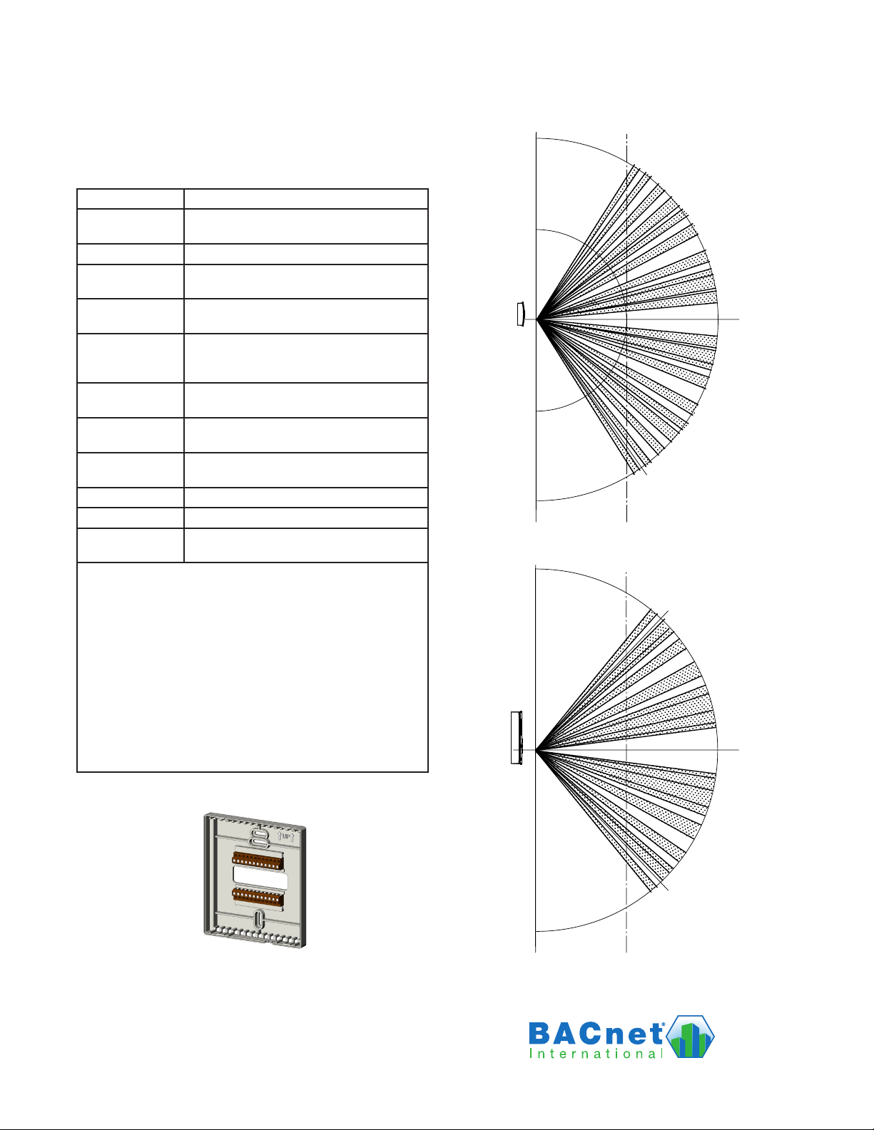
For optimum temperature sensor performance,
the MAR7000 must be mounted on an interior
wall and away from heat sources, sunlight,
windows, air vents, and air circulation
obstructions (e.g., curtains or furniture). Install it
where the motion sensor will have unobstructed
view of the most typical trac area.
If replacing an existing thermostat, label wires as
needed for reference when removing the existing
thermostat.
CAUTION
Installing a 6-input model on a (powered) 3-in-
put backplate (see page 5) will permanently
damage the controller.
To prevent mounting screw heads from touching
the circuit board in the thermostat, use only the
supplied mounting screws. Using screws other
than the type supplied may damage the controller.
1. Complete rough-in wiring at each location
prior to thermostat installation. Cable
insulation must meet local building codes.
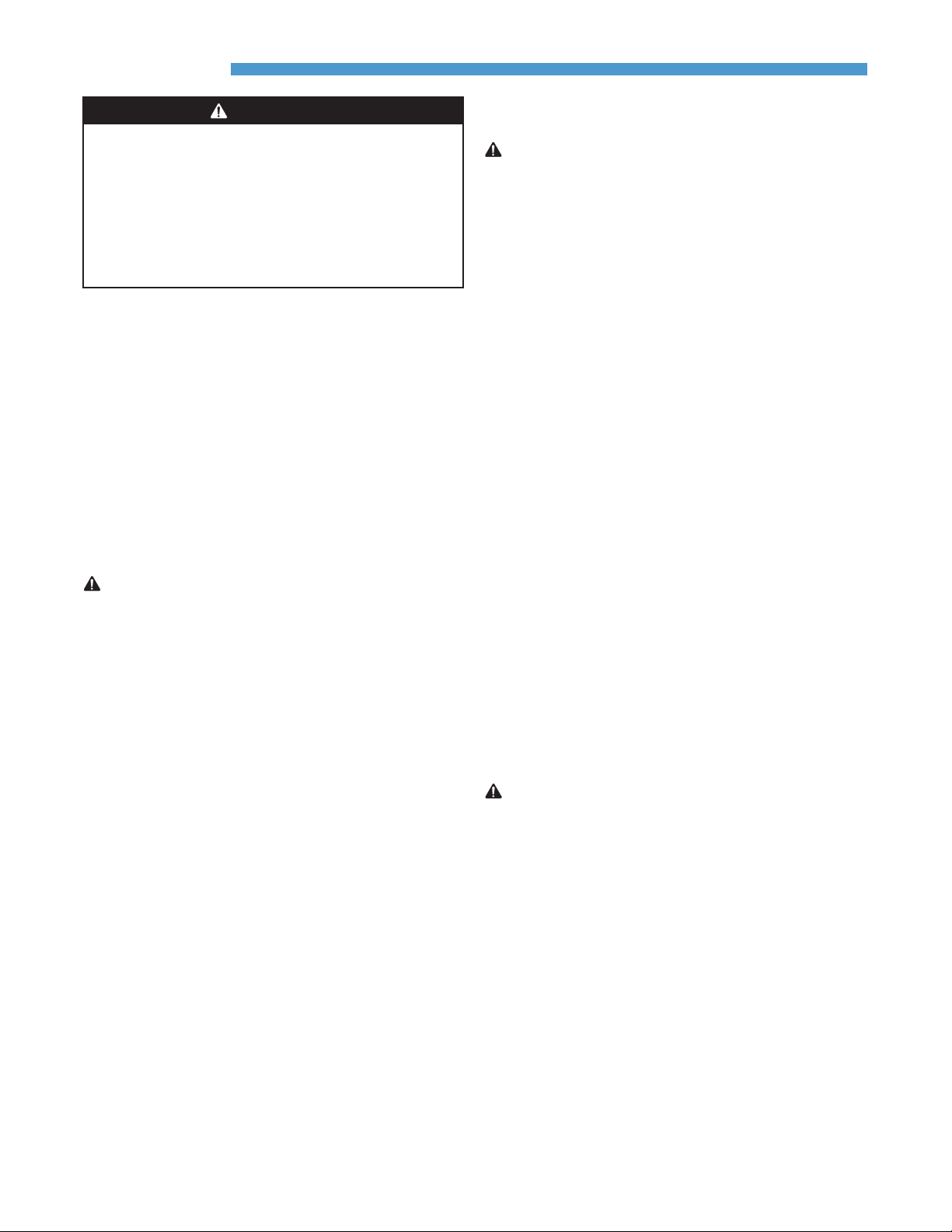
2. Push in on the tabs (two on top and boom),
and pull the cover away from the backplate
(mounting base).
3. Route the wiring through the backplate.
4. With the embossed UP toward the ceiling,
fasten the backplate directly to a vertical 2 x 4
inch wall handy-box.
5. Make the appropriate connections to the
terminal blocks. (See Connections and Wiring
on page 4.)
6. Seal the hole for wires behind the mounting
base with non-ammable insulation or puy.
7. Snap the MAR7000 cover over the backplate
while being careful not to pinch or dislodge
any wiring.
Installation
WARNING
ALWAYS TURN OFF POWER AT THE MAIN
POWER SUPPLY BEFORE INSTALLING,
CLEANING, OR REMOVING THE MAR7000.
TURN OFF POWER AT THE MAIN SERVICE PANEL
BY REMOVING THE FUSE OR SWITCHING THE
APPROPRIATE CIRCUIT BREAKER TO THE OFF
POSITION BEFORE REMOVING AN EXISTING
THERMOSTAT OR INSTALLING A NEW ONE.

MAR7000 5 1/2013, P/N 01757 Rev. B
MS/TP Network End-Of-Line Termination
(3 Input Models)
Network Wiring
For MS/TP communications, connect the EIA-485
wiring to –A and +B terminals on the backplate.
Connect the –A terminals in parallel with all other
–A terminals on the network and the +B terminals
in parallel with all other +B terminals. (See MS/TP
Network End-Of-Line Termination on page 5 and
Terminals and Connections on page 6.) Connect
the shields of the cable (Belden cable #82760 or
equivalent) together at each device with a wire
nut or equivalent.
For Ethernet or IP communications, plug an
Ethernet cable directly into the RJ-45 jack on the
back of the MAR7000.
MS/TP EOL (End-Of-Line) Termination
The controllers/thermostats on the physical ends
of the EIA-485 wiring segment must have end-
of-line termination installed for proper network
operation. (See MS/TP Network End-Of-Line
Termination and EOL and Pull-Up Switch
Resistor Positions on page 5.) If an MAR7000 is at
the physical end of the MS/TP network line, set
both the EOL termination switches to On (to the
right/up) on the back of the circuit board. If not
on the end, ensure that both switches are O (le/
down).
10K Ω0-12 V
Input Pull-Up Switches
EOL
Switches
ON
OFF
Pushed Left
Pushed Right IN2
IN3
IN4
IN7
IN8
IN9
1
2
3
4
5
6
3
4
3
4
IN4 =
5
6
10K Ω0-12 V
5
6
IN3 =
7
8
7
8
IN2 =
7
8
EOL =
Pushed Left Pushed Right
1
2
ON
OFF
1
2
10K Ω0-12 V
10K Ω0-12 V
EOL: On OnOff Off Off
MS/TP Network
EOL and Pull-Up Switch Resistor Positions
(6 Input Models)
10K Ohm
0-12 VDC
Input Pull-Up Switches
EOL
Switches
ON
OFF
Switch Pushed Up
Pushed Down
IN2 IN3 IN4 IN7 IN8 IN9
(CO2 Models)
Input Connections
Passive input devices require pull-up resistors in
the circuit. For passive input devices (e.g., switch
contacts and Type III 10K ohm thermistors) on
the external inputs, set the pull-up switches on
the back of the circuit board to the 10K position.
For active voltage devices, set the switches to the
0–12 VDC position. (See EOL and Pull-Up Switch
Resistor Positions on page 5 and Terminals and
Connections on page 6.)
NOTE: Unlike the EOL switch pairs, the
INPUT switch pairs must NOT have
both switches set in the same direction.
ALL the input pull-up resistor switch
pairs must be fully latched in either
10K Ohm or 0–12 VDC position even if
a switch pair has no input connected!
A single incorrect switch position may
cause errors in multiple inputs.
NOTE: Inputs do not support 1K ohm RTDs.
NOTE: IN1 is the room temperature sensor AI1.

MAR7000 6 1/2013, P/N 01757 Rev. B
Output Connections
Switched (Relay) Common and Relays
CAUTION
Relays are for Class-2 voltages (24 VAC) only.
Do not connect line voltage to the relays!
Connect the device under control between the
desired output terminal and the related SC
(Switched Common for relays). For the bank of
three relays, there is one Switched (relay) Common
connection. (See Switched (Relay) Common and
Relays on page 6.) Connect the SC terminal to the
PHASE side of 24 VAC.
Power Connection
The MAR7000 requires an external, 24 volt, AC
power source. Use a Class-2 transformer to supply
power. Connect the transformer’s neutral lead to
the 24 VAC Common/–/C terminal and the AC
phase lead to the 24 VAC Phase/~/R terminal. (See
Terminals and Connections on page 6.) Power is
applied to the MAR7000 when the transformer is
powered.
Powering only one controller/thermostat from
each transformer is recommended. If installing
a MAR7000 in a system with other controllers/
thermostats powered from a single transformer,
however, phasing must be correct and the total
power drawn from the transformer must not
exceed its rating.
Relay 3 (or 6)
SC 1–3 (or 4–6/7)
Relay 2 (or 5)
Relay 1 (or 4/7)
One Switched
Common
Connection
Per Bank of
Three
Normally
Open Relays
Do not aach a device that draws current
exceeding the MAR7000’s output capacity.
Maximum output current is 1 A for individual
relays @ 24 VAC/VDC or a total of 1.5 A per bank
of 3 relays (relays 1–3 and 4–6). Relays are NO,
SPST (Form “A”).
+B
–A
IN4
IN3
GND
IN2
Common/–/C
Phase/ /R
(Not connected)
SC 7 (~24 VAC)
(Not connected)
Relay 7 (VENT)
Relay 6 (HUM)
SC 4–6 (~24 VAC)
Relay 5 (W2)
Relay 4 (Y2)
Relay 3 (O/B | W1)
SC 1–3 (~24 VAC)
Relay 2 (Y1)
Relay 1 (G)
Relay Outputs
(Wiring Cutout in Backplate)
MS/TP
Network
Inputs
24 VAC
(Wiring is
dependent on
application)
(HP | AC)
*(Not Connected
in Initial Release)
**
*
*
*
IN9
IN8
GND
IN7
+B
–A
IN4
IN3
GND
IN2
Common/–/C
Phase/ /R
(Not connected)
SC 7 (~24 VAC)
(Not connected)
Relay 7 (VENT)
Relay 6 (HUM)
SC 4–6 (~24 VAC)
Relay 5 (W2)
Relay 4 (Y2)
Relay 3 (O/B | W1)
SC 1–3 (~24 VAC)
Relay 2 (Y1)
Relay 1 (G)
Relay Outputs (HP | AC)
(Wiring Cutout in Backplate)
MS/TP
Network
Inputs
24 VAC
(Wiring is
dependent on
application)
Inputs
NOTE: IN1 is the room
temp. sensor AI1
NOTE: SC = Switched
(Relay) Common
IP/Ethernet Network
(Optional)
(3 Input)
(6 Input—CO2 Model Terminals Are Rotated)
Terminals and Connections
Label Function (6 Input Models with CO2) Object
(Internal) Space CO2 Sensor AI10
(IN9) (Unused) AI9
(IN8) Remote Motion Sensor AI8
(IN7) Discharge Air Temp. (DAT) AI7
(Internal) Occupancy Status (Motion Sensor) BI6
(Internal) Space Humidity Sensor AI5
IN4 Outside Air Temp. (OAT) AI4
IN3 (Unused) AI3
IN2 Fan Status (FST) AI2
(Internal) Space Temperature Sensor AI1
VENT Ventilation BO7
HUM Dehumidification BO6
W2 Heat 2 BO5
Y2 Cool 2 BO4
W1 or O/B Heat 1 (AC) or Reversing Valve (HPU) BO3
Y1 Cool 1 BO2
G Fan BO1
NOTE: AI8 0-3 VDC contact closure
0 = Closed
3 = Open

MAR7000 7 1/2013, P/N 01757 Rev. B
WED 11/19 3:20 PM
COOL:
OCC:
FAN:
HUM: 36% RH
Configuration and Basic Operation
Home, Main Menu, and Override Screens
Home Screen
Configuration Screens
MAIN MENU
ABOUT
ADVANCED
ALARM
DATE/TIME
SCHEDULE
SETPOINTS
SYSTEM
Navigation
Navigate the menus and change seings by press-
ing a combination of various arrow buons and
the Enter buon. Push the:
• Enter buon to select and/or exit value editing.
• Up or Down buon to move among entries.
• Right or Le buon to move among value
elds.
• Le buon to return to the Home screen.
Room Temp. Setpoint Adjustment
From the Home (temperature display) screen,
press the Up or Down arrow buon once to view
the existing setpoint.
To temporarily change the setpoint, press the Up
or Down arrow buon repeatedly until the desired
seing is displayed and press Enter. (If Enter is not
pressed, the display will return to the Home screen
aer about ten seconds and the new setpoint value
will still be saved.) The new setpoint will hold
until the next schedule change.
To permanently change the setpoint for occupied
mode, go to the Setpoints section under the Main
Menu. (In the Setpoints menu, heating/cooling
setpoints/setbacks and deadband can be changed
with, if required, the correct password access.)
Main Menu and Settings
From the Home (temperature display) screen,
press the Right arrow buon to enter the Main
Menu. You may need to enter a password to
change any seings.
FAN MODES
UNOCC:
OCC: AUTO
AUTO
Override Screens
NOTE: Access to the Main Menu, setpoint
adjust, and System/Occupancy/Fan
override may require a password.
Enter
Right
(Menu)
Left
(Override)
Down (Setpoint)
Up (Setpoint)
H/C, Fan, Occupancy, and Override
When the fan is commanded to run, the animat-
ed “FAN” icon rotates. When the fan command
stops, the fan icon is motionless.
The “OCC” icon shows a sun when in Occupied
mode and a quarter moon when in Unoccupied
mode.
HEAT or COOL will show (and be animated
when there is an active command), depending
on the current mode. This can also be turned
OFF.
To override these modes from the Home (temper-
ature display) screen, press the Le arrow buon.
Press Up or Down to get to the desired line and
then Enter (twice) to edit the mode seing. Press
Leto exit to Home.
(Configuration)
(Setpoint Adjustment)
(Override)

MAR7000 8 1/2013, P/N 01757 Rev. B
Configuration, General
To congure the MAR7000, navigate the menus
and change seings by pressing a combination of
buons. Press the Right (Menu) buon and then
the:
• Enter buon to select and/or exit value editing.
• Up/Down buon to move among entries (up/
down lines).
• Le/Right buon to move among value elds
(le/right spaces).
• Le buon to return to the Home screen.
NOTE: If appear at the top of the screen
(such as in the Main Menu), scroll up
or down to see the rest of the menu’s
o-screen choices.
MAIN MENU
ABOUT
ADVANCED
ALARM
DATE/TIME
SCHEDULE
SETPOINTS
SYSTEM
ADVANCED
APPLICATION
CB PROGRAMS
COMMUNICATION
DATE/TIME
DEVICE
INPUTS
LIMITS
(See
menus
on the
following
pages)
NOTE: IMPORTANT NOTES ABOUT SOME
OF THE MENUS ARE ON THE
FOLLOWING PAGES. BUT NOT ALL
THE MAR7000 MENUS HAVE NOTES
HERE!
Advanced Menu
ADVANCED
APPLICATION
CB PROGRAMS
COMMUNICATION
DATE/TIME
DEVICE
INPUTS
LIMITS
The Advanced Menu displays various submenus.
Not all submenus can be seen on the screen at
one time. Scroll up or down to see additional
submenus.
(Advanced) Application Options
APPLICATION
DEGREES SCALE: °F
APP:
OPT: 1H/1C
ADDITIONAL SETUP
AC
ADDITIONAL SETUP
COMPRESSOR
DAMPER
FAN
HUMIDITY
SENSORS
VENT
Be sure to select the correct °F/°C temperature
scale FIRST! To change the temperature
scale aer the application is congured, the
selected application will need to be reset to Not
Congured.
The type of application (as well as the model of
MAR7000) aects the context-sensitive options
under Additional Setup.
Auxiliary Heat (Heat Pump Only) Setup
AUX HEAT SETUP
AUX HEAT:
DELAY (MINS): 60
COMP OAT LOW: 40° F
COMP LOCKOUT
For HPUs, auxiliary heat can be set for none,
with compressor lockout, or without compressor
lockout.
The Delay time controls how long the space tem-
perature must be below the auxiliary heat’s start
temperature before auxiliary heat will turn on.

MAR7000 9 1/2013, P/N 01757 Rev. B
Comp OAT Low (AV17) is the outside air temper-
ature value, below which the compressor is locked
out (when lockout is enabled). The user interface
min./max. limits are 5 and 50 degrees, with a de-
fault value of 40 degrees F.
Damper Setup
DAMPER SETUP
ECON:
ECON ENBLE TEMP: 55° F
EN/DIS
Enable an economizer for “free” cooling. Even if
disabled, CO2 models will still operate the damp-
er?
Fan Setup
FAN SETUP
OFF DELAY (SECS):
UNOCC: AUTO
OCC: AUTO
0
NOTE: For a Fan Fail Alarm, see Sensor Setup on
page 10 and Alarms on page 14.
Humidity Setup
HUMIDITY SETUP
DEHUMIDIFICATION DEHUMIDIFICATION
DEHUM:
DEHUM SETPT: 55 %RH
DEHUM DEADBAND: 5%RH
ENABLE
NOTE: If a dehumidication option is enabled,
the Space Humidity Alarm will also be
enabled. See Alarms on page 14.
IOA (Intelligent Occupancy Anticipation)
IOA SETUP
IOA:
OPT START: ENABLE
WINDOW (SECS): 1800
ENABLE
IOA is a substitute for manually entering sched-
ules. When IOA is enabled, it “learns” a schedule
by sensing motion.
The IOA turns occupancy mode on (for 15 min-
utes as a default) whenever motion is detected.
(See System Setup on page 16.) But a single detec-
tion does not modify the schedule. For IOA to
learn/modify the schedule, it must detect motion
at least once during four consecutive “quarter
windows” (1800 seconds or 30 minutes is the
default for a full window). To change the schedule
(with the default seing) aer an initial detection,
motion must also be detected at least once during
the second quarter of the window (approximately
minutes 8–15), third quarter (minutes 16–22), and
fourth quarter (minutes 23–30).
When IOA is enabled, schedules manually entered
in the Schedule menu will be overridden and
modied. During a learned “occupied” time, if no
motion is sensed for 15 minutes (default), IOA will
switch the system to unoccupied. (To adjust the
motion sensing time, see System Setup on page 16.)
Aer IOA creates a particular schedule, it makes
further modications as needed. If no motion dur-
ing a scheduled On time is detected two consecu-
tive weeks on the same day of the week, that On
time is cleared. (For example, if no one is present
in a room for two consecutive Tuesdays, then the
scheduled IOA start time for Tuesday is cleared.)
When Optimum Start is enabled, the FlexStat
soon “learns” the amount of time required to
reach the setpoint from the setback/setup tem-
perature. It will then adjust the actual start time
needed to reach the desired setpoint at the begin-
ning of the scheduled On times. It will also make
seasonal temperature adjustments if an outside air
temperature sensor is connected appropriately.
Motion Sensor
MOTION SENSOR
MOTION OCC:
STATE: OCCUPIED
ENABLE
During scheduled “o” times, the motion sen-
sor will start occupancy override (for 1 hour as a
default) when it detects motion. Occupancy over-
ride will end (with the default seing) 1 hour aer

MAR7000 10 1/2013, P/N 01757 Rev. B
(Advanced) Communications (BACnet)
COMMUNICATIONS
ACTIVE:
STATUS: SOLE MASTER
ETHERNET SETTINGS
IP SETTINGS
FOREIGN DEV SETTINGS
MS/TP SETTINGS
CONFIGURE
COMMUNICATIONS
ACTIVE:
STATUS: ACTIVE
MAC: 00:D0:6F:89:00:01
ETHERNET
COMMUNICATIONS
ACTIVE:
STATUS: ACTIVE
IP ADDRESS: 192.168.1.254
SUBNET MASK: 255.255.0.0
GATEWAY: 255.255.255.255
UDP PORT: 47808
IP
COMMUNICATIONS
ACTIVE:
STATUS: ACTIVE
IP ADDRESS: 172.16.1.254
UDP PORT: 47808
TIME TO LIVE (SECS): 600
FOREIGN DEVICE
COMMUNICATIONS
ACTIVE:
SOLE MASTER
MAC ADDRESS: 1
BAUD RATE: 38400
AUTO-BAUD: OFF
MAX MASTER: 127
MS/TP
For MS/TP communications, connect the EIA-485
wiring to –A and +B terminals on the backplate
(see the relevant model’s installation guide). For
Ethernet IP, and Foreign Device communications
(on relevant “E” models), plug an Ethernet cable
directly into the RJ-45 modular jack on the back.
To set protocol and parameters for BACnet
communications:
1. Select Congure.
2. Select desired protocol and seings.
3. Restart the MAR7000 for the new protocol to
become active. (See Reseing the MAR7000 on
page 21.)
NOTE: Even if MS/TP is the only option
in rmware R2.0.0.x and later,
CONFIGURE MUST FIRST BE
SELECTED before any of the values can
be changed! Otherwise the values are
read only.
Only one protocol can be enabled at any time.
The IP/Ethernet modes do not serve as routers
for the MS/TP connection.
For MS/TP EIA-485 communications, the Max
Master is the highest MAC address a device
will aempt to locate when polling for master
devices on the local network. To avoid possible
communication issues with the network, the Max
Master number should be the lowest number
needed for that network.
motion was last detected. The length of occupancy
override is congurable in the System menu. See
System Setup on page 16.
The State eld monitors whether motion has been
detected during the last scan of the motion sensor
input (BI6). Detected motion will show an “occu-
pied” state. This can be used during troubleshoot-
ing to determine if motion is being detected.
Sensor Setup
SENSOR SETUP
IN 2:
IN 7: DISCHARGE AIR
IN 8: REMOTE MOTION
FAN STATUS
Input 2 (AI2) can be congured for fan status
(dry contact) or unused. If set for fan status and
no closed contact is detected when there is a call
for fan operation, a Fan Fail Alarm is created. See
Alarms on page 14.
Input 7 (AI7) can be congured for discharge air
temperature (Type III thermistor ) or unused. If
the discharge air temperature is below 40° F, the
compressors will be locked out.
Input 8 (AI8) can be congured for a remote
motion sensor (dry contact) or unused. If both
internal and external motion sensors are active,
motion detected by either will be used to
determine occupancy.
Vent Setup
VENT SETUP
OCC VENT:
UNOCC VENT: DISABLE
FRESH AIR PURGE:
–LENGTH (MINS): 0
–INTERVAL (MINS): 0
ENABLE
If OCC VENT is enabled, during occupied periods
an automatic fresh air purge x minutes in length
occurs with an interval of every y minutes accord-
ing to the values selected. (UNOCC VENT would
work similarly.) In addition to the standard peri-
odic purge, see the pre-start purge in IOA (Intel-
ligent Occupancy Anticipation) on page 9.

MAR7000 11 1/2013, P/N 01757 Rev. B
Max Info Frames (view only) is the maximum
number of information frames (data packets) that
a controller may send out before it must pass the
token.
For IP and IP Foreign Device communications,
consult with the system administrator for the
appropriate seings for the IP Address, Subnet
Mask, Gateway, and UDP Port.
Ethernet communications are essentially plug-
and-play, and the MAC address is not changeable.
(Advanced) CO2 Sensor
CO2 SENSOR
SENSOR INFO
CO2 SENSOR INFO
MODEL: T6615
SUB VOL: A15
SW DATE: 090217
S/N: AB00011759
CO2: 873
ELEVATION: 0
STATUS: NORMAL
Set the desired CO2 setpoint under the Setpoints
menu. See Setpoints on page 16.
For maximum sensor accuracy, enter the eleva-
tion (altitude) above sea level of the building’s
location. (The default value is 0.) Elevation for any
particular location can be found at such sources as
www.earthtools.org. (For very tall buildings, the
upper oors would have a higher elevation than
lower oors.)
Aer power is rst applied or the FlexStat is
restarted, the sensor goes through a warm-up for
approximately half a minute. During the time the
sensor count will be 0 ppm and the Status line
would display WARMUP instead of NORMAL.
The sensor and its rmware are identied by the
model, the compilation subvolume (SUB VOL),
compilation date (SW DATE in yymmdd format),
and serial number.
NOTE: With the CO2 sensor enabled, a trend log
is automatically generated. See Trend
Viewer on page 16.
The CO2 models have a patented self-calibration
technique designed to be used in applications
where concentrations will drop to outside ambi-
ent conditions (approximately 400 ppm) at least
three times in a 14 day period, typically during
unoccupied periods.
(Advanced) Date/Time
DATE/TIME
DATE:
TIME: 1:43:59 PM
UTC OFFSET: 300
DST ENABLE: TRUE
DST AUTO: TRUE
DST START:
>2ND SUN MAR 2:00 AM
APRIL 11 2009
If the MAR7000 is used in a BACnet network with
UTC (Coordinated Universal Time) synchroniza-
tion (via broadcasting or addressing a single ther-
mostat) set the UTC Oset value. The UTC Oset
value is in minutes and corresponds to the distance
of the local time zone to the zero degree meridian.
For example, USA/Canada Pacic Standard Time
(8 hours) = 480 minutes and USA/Canada Eastern
Standard Time (5 hours) = 300 minutes.
In stand-alone operation or networks that do not
have UTC broadcasts, seing this value is not nec-
essary.
NOTE: The BACnet standard for this oset
value is: “The time zones to the west
of the zero degree meridian shall be
positive values, and those to the east
shall be negative values.” The value is in
minutes, not hours.
For areas that observe DST (Daylight Saving
Time), select True/On for DST ENABLE and DST
AUTO. The DST period is currently the second
Sunday of March through the rst Sunday of
November, but these rules can be changed in the
menu if the ocial period changes or if the in-
stalled location needs a schedule adjustment for
beer operation.
NOTE: If DST is enabled but the Auto seing is
not, the actual calendar dates (instead of
using the general rules) will need to be
entered every year.

MAR7000 12 1/2013, P/N 01757 Rev. B
(Advanced) Security Levels and Passwords
SECURITY
ACCESS LEVELS
PASSWORDS
ACCESS LEVELS
SETPOINT ADJ:
MAIN MENU: ADMIN
SYSTEM MODE: OPER
OCC OVERRIDE: USER
FAN OCC/UNOCC: OPER
NONE PASSWORDS
USER:
OPERATOR:
ADMIN:
1 0 0 0
1 2 3 4
5 6 7 8
Access to the Main Menu, Setpoint Adjust, and
System/Occupancy/Fan seings have a default
password level of User. This level can be changed
for each function to None, Operator, or Adminis-
trator through the Access Levels menu. Passwords
are set in the Passwords menu.
Any person can view the display but might not
be able to change any seings without logging in
with one of the three levels of passwords:
• None (Level “0”): No password is required
(everyone has access). (For example, anyone
can adjust a setpoint with Access Level None
even if all other functions require a password.)
• User (Level 1): See the Menu Items Access
Levels chart on the next page.
• Operator (Level 2): See the Menu Items Access
Levels chart.
• Administrator (Level 3): Can access all menus
and change all editable values. DO NOT
FORGET THIS PASSWORD!
NOTE: Seing a password to (the default)
0000 eliminates the password prompt
and allows full access for that level.
If no password is set for ADMIN, no
password prompt will occur. If any
password is set for ADMIN, the menu
items accessible at the various levels
are shown in the following chart.
NOTE: Changes in security levels and/or
passwords take eect when the current
Administrator log-in has timed out.
Log-ins last until 60 seconds (default)
aer the last buon press. Desired length
of inactivity time-out can be changed in
the Systems submenu.
NOTE: When seing a password, the Up buon
increases the alphanumeric value (0
through 9 and then A through Z).
(Advanced) Inputs
INPUTS
1: SPACE TEMP
2: FAN STATUS SENSOR
3: AI_03
4: OUTSIDE AIR TEMP
5: SPACE HUMIDITY
7:
8: REMOTE MOTION SENSOR
DISCHARGE AIR TEMP
INPUT #7
DISCH AIR TEMP
VALUE: 60.0° F
CAL. OFFSET: 0.0
OUT-OF-SERVICE: FALSE
FILTER WEIGHT: 6
SENSOR: 10K TYPE III
Inputs vary according to model, selected applica-
tion, and selected application options. See (Ad-
vanced) Application Options on page 8.
Value will show a temperature reading or a volt-
age (0.0 to 3.0), depending on the sensor.
Analog sensors can be calibrated changing the
value in Calibration Oset.
“Out-of-Service: False” means the input is active
(not out of service). If it is “true,” the input is inac-
tive. The menu only shows the status.
(Advanced) Temp. Setpoint Limits
LIMITS
OCC MIN CLG:
OCC MAX HTG: 80° F
UNOCC MIN CLG: 66° F
UNOCC MAX HTG: 80° F
MIN SETPT DIFF: 5° F
66° F
This menu permits changes to the minimum and
maximum allowed user/operator setpoint values.
(Colder Room Temperature Warmer)
Cooling
Setpoint
Heating
Setpoint
Proportional
Band
Proportional
Band
Minimum
Setpoint
Differential

MAR7000 13 1/2013, P/N 01757 Rev. B
The Down buon decreases the value.
DO NOT FORGET THE ADMIN
PASSWORD!
The required password level is specied in the
prompt.
For additional physical security and protection
from vandalism, install the MAR7000 inside a
third-party locking thermostat guard/cover (but
proper airow must be maintained).
Menu Items Access Levels
Menus User Operator Administrator
Home Screen * = Selectable, Default is User
Setpoint Adjust (Up/Down) x* x* x*
System Mode (Auto/H/C/Off) x* x* x*
Occupancy Override (On/Off) x* x* x*
Fan Modes (Auto/On/Off) x* x* x*
Main Menu* (Default is User)
About x x x
Advanced x x
Alarm x x
Date/Time x x
Schedule x x
Setpoints x x
System x x
Trend Viewer x x x
Advanced Menu
Application x
Additional Setup x
Control Basic Programs x x
Communication x
Date/Time x x
Device x
Inputs x x
Limits x x
Motion Sensor x x
Security x
Trend Logs x x
Test x x
This chart shows conditions in which an administrator password
is set (is not 0000) and default password levels are used.
(Advanced) Trend Logs
TRUE
TREND LOGS
TREND 1:
TREND 2: TRUE
TREND 3: FALSE
TREND 4: FALSE
TREND 5: FALSE
TREND 6: FALSE
TREND 7: FALSE
TREND #1
SPACE TEMPERATURE LOG
OBJECT REF: AI1
LOG ENABLE: TRUE
INTERVAL (MINS): 10
STOP W/FULL: FALSE
RESET COUNT: NO
COUNT: 256
TOTAL CNT: 613
VIEW LOG BUFFER
TL #1–SPACE TEMP
APR17 1:27PM, 71.4
APR17 2:27PM, 71.5
APR17 3:27PM, 71.6
APR17 4:27PM, 71.8
APR17 5:27PM, 76.3
APR17 6:27PM, 81.2
APR17 7:27PM, 82.3
NOTE: Space temperature (AI1) is the
default trend log #1. Depending on
conguration and options, other default
trend logs might exist.
The trend log buer may be viewed by scrolling
down and selecting View Log Buer. The buer
may also be viewed from the Main Menu by
scrolling down to the Trend Viewer (see page 16).
NOTE: The BACnet standard for log intervals
is hundredths of seconds. The simplied
display on the MAR7000 converts the
value to minutes. However, building
automation soware may display
hundredths of seconds and in dierent
ways.
NOTE: Other objects that can also be congured
for trend logs include:
• Humidity sensor = AI5
• Discharge air temperature = AI7
• Motion sensor = BI6
• Motion sensor occupancy override =
BV24
• See also the list of objects in
Terminals and Connections on page 6

MAR7000 14 1/2013, P/N 01757 Rev. B
(Advanced) User Interface (UI)
USER INTERFACE
DISPLAY BLANKING:
INACTIVITY (SECS): 60
ROTATION VALUES
SHOW TEMP TENTHS: NO
NO
Display Blanking
When Display Blanking is enabled (Y), the display
turns o at the same time the backlight goes o
(aer reset, initial power-up, or time-out). When
any buon is pressed, the display will reappear
until the time-out is reached again.
Inactivity
The menu/display/backlight time-out (seconds
since the last buon is pushed) is set in Inactivity.
Rotation Values
ROTATION VALUES
1:
2: OAT: SHOW
3: CO2: SHOW
4: UI4: HIDE
HUM: SHOW
The Rotation Values menu allows easy seing of
what applicable optional values (e.g., humidity,
outside air temperature, and/or CO2 level) will
display on the lower right of the screen (such as
“HUM: 46% RH” shown on the Hospitality Mode
sample screen). If more than one value is shown,
the values will rotate approximately every ve
seconds.
In applicable models, humidity and CO2 levels
are shown by default but can be hidden if
desired.
UI4, the fourth rotation value, is available for
custom programming.
Show Temperature Tenths (Decimals)
With R2.0.3.x and later rmware, Fahrenheit tem-
perature values on the display change in whole
degree increments by default, and Celsius values
change in 0.5° increments. Changing the default
No to Yes will show tenths of a degree values for
both scales.
This does not aect setpoint adjustments, which
are always in whole degree increments for Fahr-
enheit and half degree increments for Celsius.
Alarms
SAT 4/11 3:20 PM
COOL:
OCC:
FAN:
SERVICE HUM: 20%RH
ALARMS
* SPACE TEMP ALARM 04/11
04/11/09 08:37:56
<AI1> SPACETEMP
PRESENT VALUE = 90.1
EXCEEDS HIGH_LIMIT
<EE1>
SPACETEMPALARM
DELETE ALARM?
NO
YES
A ashing “SERVICE” on the Home screen
indicates an alarm. Built-in alarms are triggered
under these conditions:
• Space Temp Alarm—temperature outside the
range of 56 to 86° F for over 300 seconds.
• Space Humidity Alarm—humidity above 65%
for over 300 seconds. This is available only
when a dehumidication option is selected in
the Humidity setup). See Humidity Setup on
page 9.
• Fan Fail Alarm—no fan status signal within
ve seconds of call for fan (and Input 2 is
congured for the fan status sensor option).
See Sensor Setup on page 10.
• CO2 Alarm—carbon dioxide level has been
above the setpoint (default 1000 ppm—see
Setpoints on page 16) or below 250 ppm for over
30 minutes. If the sensor reading is below 250
ppm, the sensor is not working properly—see
(Advanced) CO2 Sensor on page 11.

MAR7000 15 1/2013, P/N 01757 Rev. B
Date/Time
DATE/TIME
DATE:
TIME: 1:43:59 PM
APR 11 2009
More options (such as UTC oset and daylight
saving time options) are available in the (Ad-
vanced) Date/Time menu (see page 11).
Schedules
SCHEDULE
ENTIRE WEEK [MON–SUN]
WEEKDAYS [MON–FRI]
WEEKEND [SAT–SUN]
INDIVIDUAL DAYS
HOLIDAYS
ENTIRE WEEK
1:
2: 5:15:00 PM OFF
3:
4:
5:
6:
[—>] DELETES ENTRY
7:30:00 AM ON
This menu allows manual creation of schedules.
For automated creation, see IOA (Intelligent
Occupancy Anticipation) on page 9. IOA overrides
any O times in a manual schedule.
The Holiday entries will override the normal
occupied weekly schedule entries and keep those
days’ seings at their setback values. Setback
values are entered in the Setpoints menu (see
Setpoints on page 16). (See also the maximum and
minimum setpoint values in in (Advanced) Temp.
Setpoint Limits on page 12.)
To enter weekly schedules for occupied (ON) and
unoccupied (OFF) times, press:
NOTE: If a day of a week (e.g., Friday) has a
dierent schedule than the rest, using
the Weekdays menu rst and then
modifying that one day in the Individual
Days menu may be easier (two entries)
than entering schedules for each day
separately in the Individual Days menu
(ve entries).
NOTE: The last overlapping entry overrides
any other. For example, suppose the
WEEKDAYS menu is used to set all
weekdays for 7:00 AM ON and 5:00 PM
OFF, and then the INDIVIDUAL DAYS
menu is used to add some additional
evening meeting ON times for Tuesday
and Wednesday. If the WEEKDAYS
menu is later used to change the ON
time from 7:00 to 7:15, schedules for
all the individual week days will be
reset to conform to what appears in
the WEEKDAYS menu and any special
times for individual days will be
erased. (Special day schedules will then
need to be added again through the
INDIVIDUAL DAYS menu).
HOLIDAYS
HOL1:
HOL2: MAR 21 2009
HOL3: MAY 26 2009
HOL4: JULY 4 2009
HOL5: SEPT 1 2009
HOL6: NOV 27 2009
HOL7: NOV 28 2009
JAN 1 2009
The Holiday entries will override the normal
occupied weekly schedule entries and keep
those days’ seings at their setback values. Set-
back values are entered in the Setpoints section
of the Main Menu. (See also the maximum and
minimum cooling/heating setpoint values in (Ad-
vanced) Temp. Setpoint Limits on page 12.)
NOTE: For maximum eciency, if Optimum
Start is enabled, set On times in
schedules for when the room
temperature should reach the setpoint,
not when heating/cooling equipment
should start (which would be earlier).
See IOA (Intelligent Occupancy
Anticipation) on page 9.

MAR7000 16 1/2013, P/N 01757 Rev. B
Setpoints
SETPOINTS
COOL 1 SETPT:
HEAT 1 SETPT: 68° F
DEHUM SETPT: 55% RH
COOL SETBACK: 80° F
HEAT SETBACK: 64° F
MIN SETPT DIFF: 5°
CO2 SETPOINT (PPM): 1000
CO2 DEADBAND (PPM): 100
75° F
In the Setpoints menu, setpoints and setbacks
for various values are set. (The current room
temperature setpoint can also be manually
changed from the Home menu.)
System Setup
SYSTEM
SYSTEM ENABLE:
OVRRIDES:
– SETPT (HRS): 1.0
– MOTION (MINS): 15
AUTO
Setpoint Override on this menu is the amount of
time (in hours) a manual change in the setpoint
(via the Up and Down buons) will be allowed to
override the scheduled setpoint. When the time is
set to 0, the override state will last until the next
schedule change.
Motion Override on this menu is the amount of
time (in minutes) detected motion will temporar-
ily place the system into occupied mode. The time
is measured since the last motion detection.
NOTE: Occupancy override can also be removed
while on the Home screen by pushing
the le buon, navigating to OCC,
hiing Enter twice, and changing ON
to OFF. See H/C, Fan, Occupancy, and
Override on page 7.
Trend Viewer
TREND VIEWER
1:
2: SPACE HUMIDITY 27
3: FAN 19
4: COOL 1 18
5: COOL 2 21
6:
7:
SPACE TEMP 34
TL #1 SPACE TEMP
APR11 1:27PM, 70.3
APR11 2:27PM, 71.3
APR11 3:27PM, 71.6
APR11 4:27PM, 71.8
APR11 5:27PM, 76.3
APR11 6:27PM, 81.2
APR11 7:27PM, 82.3
Trend logs are set up in the (Advanced) Trend
Logs menus (see page 13).

MAR7000 17 1/2013, P/N 01757 Rev. B
Troubleshooting
Alarm Issues
Alarm, (False) Fan Fail
• Check conguration. Be sure the Fan Status
option is not selected when there is no sensor/
switch for it.
• Check that the IN2 (fan status) input pull-up
resistor switches are fully latched in the correct
positions. Any passive, dry contact should use
the 10K Ohm seing. (See Input Connections
on page 5.)
• Check IN2 (fan status) input wiring.
• Check the connected fan status sensor/switch.
Alarm, (False) Space Temp. or Humidity
• See Alarms on page 14.
• See Temperature Reading Is Incorrect on page
18.
• See Temperature Setpoint Is Not Maintained
on page 19.
Cover, Display, and Reset Issues
Cover Binds on Backplate
• Be sure top and boom tabs are both pushed
in when removing the cover.
• Carefully remove the MAR7000 cover from
the backplate and inspect for bent pins and/
or terminal socket connectors. If cover pins
are bent, use a needle-nose pliers to straighten
them. If socket connectors are bent, use
a pointed object (such as a thumbtack or
straightened paperclip) to straighten them.
(Pushing the pointed object into the socket
from the back side can be helpful.)
• When installing the cover, it may be helpful to ap-
ply more pressure toward the boom of the cover.
• Replace the backplate.
NOTE: When installing the cover on the
backplate, be sure to not pinch or
dislodge any wiring. Do not use
excessive force. If there is any binding,
pull out cover and examine pins and
terminal socket connectors.
Display Is Blank (or Erratic)
• If the display comes on when a buon is
pushed, Display Blanking is enabled. (See
System Setup on page 16.)
• Carefully remove the MAR7000 cover from
the backplate, check pins and connectors, and
reinsert. (See Cover Binds on Backplate on
page 17.)
• Check for a tripped circuit breaker to the
transformer.
• Check for proper supply voltage from the
transformer and that the transformer has
enough capacity (VA) for all connected devices
(see their respective specications).
NOTE: Wiring must be adequate to avoid
excessive voltage drop on long runs!
Allow plenty of “cushion.” A meter
may be too slow to register transient
dips or peaks during startup. See Wiring
Issues on page 20.
• Put another MAR7000 on the installed
backplate, and if the second MAR7000
functions properly, replace the rst MAR7000.
• See also Display Keeps Reseing on page 18.

MAR7000 18 1/2013, P/N 01757 Rev. B
Display Freezes (Buttons Have No Effect)
• Carefully remove the MAR7000 cover from
the backplate and ensure the WD (watch dog)
jumper is installed on the two pins toward the
center of the board. The jumper is temporarily
removed during a rmware installation/
update and should be reinstalled when the
process is completed. Reinstalling the cover on
the backplate will restart the MAR7000.
Display Keeps Resetting
• Carefully remove the MAR7000 cover from
the backplate, check pins and connectors, and
reinsert. (See Cover Binds on Backplate on
page 17.)
• Check for proper supply voltage from the
transformer and that the transformer has
enough capacity (VA) for all connected
devices. (See their respective specications.)
NOTE: Wiring must be adequate to avoid
excessive voltage drop on long
runs! Allow plenty of “cushion” in
measurements A meter may be too
slow to register transient dips or peaks
during startup. See Wiring Issues on
page 20.
• Put the MAR7000 on a backplate connected
to a (test) transformer with short wiring and
no other connected devices. If the MAR7000
works with the test transformer, the wiring
and/or transformer in its previous location is
inadequate. If it does not work with the test
transformer, replace the MAR7000.
• Put another MAR7000 on the installed
backplate, and if the second MAR7000
functions properly, replace the rst MAR7000.
• Check that the correct input type is selected
on the Inputs screen. A Type III thermistor is
the default for external inputs. See (Advanced)
Inputs on page 12.
• Check input wiring. See Wiring Issues on page
20.
• Check connected sensors.
• Restore the MAR7000 to factory seings
(see Reseing the MAR7000 on page 21) and
recongure.
Motion/Occupancy Sensor Does Not Work
• Aer an initial power-up or restart, the
motion/occupancy sensor requires about 30
seconds before it will begin responding to
motion.
• The motion/occupancy sensor initiates
override only during “o” times in the
schedule. See Schedules on page 15.
• Check that the motion sensor is enabled and
detects motion. See Motion Sensor on page 9.
• The MAR7000 must be installed where there
is a clear view of typical trac area (reliable
range is out to about 33 feet). Remove or move
obstacles. Reinstall the MAR7000 in a more
optimal location if necessary.
Temperature Reading Is Incorrect
• Check that the correct °F/°C temperature
scale is selected—see (Advanced) Application
Options on page 8.
• Aer applying power for the rst time (or
aer an outage), allow the MAR7000 to self-
calibrate a few minutes before verifying
temperature reading.
• If the discrepancy is small, adjust the
calibration oset—see (Advanced) Inputs on
page 12.
• Check that the MAR7000 is NOT mounted
on an exterior wall, mounted on or near
a large thermal mass (e.g., concrete block
wall), blocked from normal air circulation by
obstructions, exposed to heat sources (e.g.,
lights, computers, copiers, coee makers) or to
sunlight (at any time of the day), exposed to
dras from windows or air vents, or exposed
to air ow through the conduit from leaks
in plenum ducts (put plumber’s puy inside
conduit to block air leaks).
• See also Input Values Are Outside Expected
Range on page 18.
Input, Sensor, and Value Issues
Input Values Are Outside Expected Range
• Check that ALL the input pull-up resistor
switches are fully latched in the correct
positions. (See Input Connections on page
5.) A single incorrect switch position may
aect multiple inputs. All input switches
must be latched in either 10K Ohm or 0–12
VDC positions even if no input is connected!
Input switch pairs (3-4, 5-6, and 7-8) must
never have both switches set in the same
direction—if switch 3 is set to the le, for
example, 4 must be set to the right (or vice
versa).

MAR7000 19 1/2013, P/N 01757 Rev. B
Temperature Setpoint Is Not Maintained
• Select Occupied mode from the Home Menu—
see H/C, Fan, Occupancy, and Override on
page 7.
• Override the fan to On from the Home
Menu—see H/C, Fan, Occupancy, and
Override on page 7.
• Check that the appropriate application is
selected—see (Advanced) Application Options
on page 8.
• Check that room temperature is being sensed
correctly—see Temperature Reading Is
Incorrect on page 18.
CO2 Level Seems Incorrect
• Aer power is rst applied or the FlexStat is
restarted, the sensor goes through a warm-up
for approximately half a minute. During the
time the sensor count will be 0 ppm.
• Check the remote CO2 sensor setup (if
applicable). For both internal and external
sensors, the highest of the two readings will
be used to control ventilation. The CO2 ppm
display (if enabled) also shows the highest of
the two levels.
• To reduce nuisance complaints by occupants
of levels being “too high,” turn o the
visibility of the CO2 level rotation in the
display. See (Advanced) User Interface (UI) on
page 14.
MS/TP Communication Issues
• Check MAC address and device instance
numbers (especially for duplicate
numbers on the network)—see (Advanced)
Communications (BACnet) on page 10.
• Check that EOL switches are fully latched in
the correct positions (see MS/TP EOL (End-
Of-Line) Termination on page 5).
• Check baud rate—see (Advanced)
Communications (BACnet) on page 10.
• Reduce the Max Master number down to
the minimum needed for that network—see
(Advanced) Communications (BACnet) on
page 10.
• See Wiring Issues on page 20.
Output, Fan, and Relay Issues
Fan Does Not Run
NOTE: The animated fan icon is coupled with
BV18 in the packaged programming (not
the actual fan output terminal).
• Select Occupied mode from the Home
Menu—see H/C, Fan, Occupancy, and
Override on page 7.
• Override the fan to On from the Home
Menu—see Home, Main Menu, and Override
Screens on page 7.
• See Wiring Issues on page 20.
• Check that the appropriate application
is selected—see (Advanced) Application
Options on page 8.
• Check the fan conguration—see Fan Setup
on page 9.
• Restart the MAR7000. Aer a low limit alarm
is generated, the fan will not run until aer
the MAR7000 is restarted. (See Reseing the
MAR7000 on page 21.)
Relay (Internal) Does Not Work
CAUTION
Relays are for Class-2 voltages (24 VAC) only.
Do not connect line voltage to the relays!
NOTE: Max. output current is 1 A for
individual relays @ 24 VAC/VDC or
a total of 1.5 A per bank of 3 relays
(relays 1–3 and 4–6). Do not aach a
device that draws current that exceeds
the corresponding value. Relays are NO,
SPST (Form “A”).
• Check current draw of load. Substitute an
output device that draws less current.
• Check that the output is on.
• See Wiring Issues on page 20.
• Restart the MAR7000. (See Reseing the
MAR7000 on page 21.)
• If Restore Factory has just been performed, see
the Note and Cautions in Restore Factory on
page 21.

MAR7000 20 1/2013, P/N 01757 Rev. B
+B
–A
IN4
IN3
GND
IN2
Common/–/C
Phase/ /R
(Not Connected)
SC 7
(Not Connected)
Relay 7
Relay 6
SC 4–6
Relay 5
Relay 4
Relay 3
SC 1–3
Relay 2
Relay 1
Outputs
NOTE: Values Shown Are Approximate!
BACnet
MS/TP
Network
Inputs
24 VAC
NOTE: SC = Switched (Relay) Common, Should
Have the Phase Side of 24 VAC Connected
(Wiring Inputs
and Outputs
Dependent on
Application)
24 VAC
}
}
10K Ohms (Thermistor),
O Ohms (Closed Contact),
Megohms (Open Contact), or
Voltage (Active Input Device)
0.1–0.2 VDC (If Network
Token Passing is Present)
}
24 VAC
(Jumper to
Turn Device
On Manually)
NOTE: Backplate Terminals Shown with MAR7000 Removed;
Outputs and Inputs Vary According to Application
Terminal Voltages and Resistances with MAR7000 REMOVED from Backplate
Wiring Issues
Installation Wiring Considerations Troubleshooting Wiring Problems
• Review Connections and Wiring on page 4.
• Remove the MAR7000 from the backplate
and inspect the terminals for loose or shorted
wires.
• Use a voltmeter and ohmmeter to check
the terminals for expected values. See the
illustration below.
NOTE: Voltage on the BACnet MS/TP terminals
changes according to the signals (passing
of the token) between controllers on the
network. No voltage may indicate a bad
connection or simply no active network.
NOTE: Wiring must be adequate to avoid
excessive voltage drop on long
runs! Allow plenty of “cushion” in
measurements A meter may be too
slow to register transient dips or peaks
during startup.
• Check the wiring at the connected devices.
CAUTION
Relays are for Class-2 voltages (24 VAC) only.
Do not connect line voltage to the relays!
CAUTION
To avoid damage from ground loops and
other communication issues in networked
MAR7000s, correct phasing on network and
power connections on ALL the networked
controllers is critically important.
• Because of the many connections (power,
network, inputs, outputs, and their respective
grounds or switched commons), be sure
wiring is well planned before installation of
conduit!
• To prevent excessive voltage drop, use a
conductor size that is adequate for the wiring
length! Allow plenty of “cushion” to allow
for transient peaks during startup.
• Make sure that conduit for all wiring has
adequate diameter for all necessary wiring.
Using 1-inch conduit and junction boxes is
recommended!
• Use external junction boxes above the ceiling
or in another convenient location as needed to
make connections that run to the MAR7000’s
junction box.
• Using multiple conductor wires for all inputs
(e.g., six conductor) and outputs (e.g., 12
conductor) is recommended. Grounds for all
the inputs can be combined on one wire.
Table of contents
Popular Thermostat manuals by other brands

Trane
Trane TR-SAS908MTW-0-F3 Product data sheet

Honeywell
Honeywell T8611C owner's manual

Honeywell
Honeywell YRTH7500D1009 - 5 Day Program Thermostat quick start guide

Peaksaver
Peaksaver Honeywell quick start guide

ICM Controls
ICM Controls SC3000L Installation, operation & application guide

Crestron
Crestron CHV-THSTAT Operation and installation guide

Danfoss
Danfoss Icon Master user guide

American Standard
American Standard Ceratherm T203.730 installation instructions

Daikin
Daikin 910193131 Installation & operation manual

White Rodgers
White Rodgers 700 installation instructions

Honeywell
Honeywell T7200 owner's manual

Pro1 Technologies
Pro1 Technologies T731W installation manual