Supco CTC PROCOMM Series User guide

To prevent damage to the thermostat, never use a sharp instrument
to press the touchscreen keys. Always press keys with your fingers.
Attention
• Possible electric shock or damage to equipment can occur.
• Disconnect power before beginning installation.
Caution
This thermostat requires 24 Volt AC Power or 2 properly installed “AA” Alkaline
batteries for
proper operation. If connecting this thermostat to a Wi-Fi network,
a 24 VAC common (C wire) is required.
For use only as described in this manual. Any other use will void warranty.
Warning
For installation by experienced service technicians only.
This thermostat is compatible with:
• Singlestageheat/coolconventionalandheatpumpsystems
• Conventionalsystemsupto2stagesofheatingand2stagesofcooling
• Heatpumpsystemsupto3stagesofheatingand2stagesofcooling
Electrical and control specifications:
• ElectricalRating:24VoltAC
• 1ampmaximumloadperterminal,6ampmaximumload
• ACPower:18to30VoltsAC
• DCPower:3.0VoltDC(2“AA”AlkalineBatteriesIncluded)
• ControlRange:45°Fto90°F(7°Cto32°C)
• TemperatureAccuracy:+/-1°F(+/-.5°C)
• OutdoorTemperatureDisplayRange:-40°Fto120°F(-40°Cto49°C)
Terminations:
Rc,Rh,C,W2/AUX,W1/E,L,A,O/B,G,Y2,Y1,K,S2,S1
1
Specifications
93257WF-100-01
Model number is located on back of thermostat.
*WirelessHumidityControlrequiresaccessorymodel9330.
See Wi-Fi Setup Guide for Wi-Fi Setup Instructions
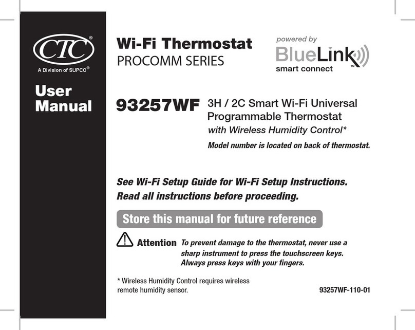
Wi-Fi Thermostat
93257WF
PROCOMM SERIES
Installer
Manual 3H / 2C Smart Wi-Fi Universal
Programmable Thermostat
with Wireless Humidity Control*
1
Specifications
2
Installation and Wiring
3
Quick Reference
4
Installer Settings
5
Wireless Remote Sensors
6
System Testing
TM
powered by
®
A Division of SUPCO®

Thermostat Location
Installthethermostatapproximately5feet(1.5m)abovetheoorinanareathathasagoodamountofair
circulationandmaintainsanaverageroomtemperature.
Avoidinstallationinlocationswherethethermostatcanbeaffectedbydrafts,deadairspots,hotorcoldair
ducts,sunlight,appliances,concealedpipes,chimneysandoutsidewalls.
Installer Manual 2
Install your new CTC
®
thermostat in 4 basic steps:
1 InstalltheSub-Base
2 ProvidePower
3 ConnectYourWires
4 AttachThermostattoSub-Base
Install the Sub-Base:
•Removethesub-basefromthebodyofthethermostat.
•Mountthesub-baseasshownbelow:
Warning
Disconnect power before beginning installation.
2
Installation and Wiring
1
UP UP
Drill 3/16” pilot holes in your
desired location. Use supplied
anchors for drywall or plaster.

3 Installer Manual
Provide Power
C
24VAC Power Terminal (C)
2
Connect Your Wires
3
+
+
• For24VoltACpower,youmustconnectthecommonsideofthetransformertotheCterminalonthethermostat
sub-base.Indualtransformerinstallations,thetransformercommonmustcomefromthecoolingtransformer.
• Forbatterypower,insertthe2supplied“AA”typealkalinebatteriesintothebatterycompartmentlocatedintherear
housingofthethermostat.MakesuretopositionthePositive(+)andNegative(-)sidesofthebatteriescorrectlywith
the+/-symbolsinthebatterycompartment.
• IfconnectingthisthermostattoaWi-Finetwork,a24VACcommon(Cwire)isrequired.
Batteries Installed as Shown
Terminal Function Description
Rc Input 24VoltACCoolingTransformer
(DualTransformerSystemsOnly)
Rh Input PowerConnection(24VoltAC
HeatingTransformer)
C Input 24VoltACTransformerCommon
W2/AUX Output (W2)2ndStageConventionalHeat
(AUX)AuxiliaryHeat(HeatPump)
W1/E Output (W1)1stStageConventionalHeat
(E)EmergencyHeat
L Input SystemMalfunctionIndicator
A Output Economizer,FreshAirorOutputControl
O/B Output (O)CoolActiveReversingValve
(B)HeatActiveReversingValve
G Output FanControl
Y2 Output 2ndStageCompressor
Y1 Output 1stStageCompressor
K - OptionalShare-a-Wire
TM
moduleconnection
S2
S1
Input OptionalWiredRemoteSensor
(indoororoutdoor)

Installer Manual 4
1 HEAT / 1 COOL Single or Dual Transformer
Set System Type to 11CONV
Rh
24VoltACPower(heatingtransformer)[note 2]
Rc
24VoltACPower(coolingtransformer)[note 2]
W1 HeatRelay
Y1 CompressorRelay
G FanRelay
C 24VoltACTransformerCommon[note 1, 3]
NOTES - Conventional Systems
[1]Optional24VoltACcommonconnection
(requiredforWi-Fi).
[2]Removefactoryinstalledjumperfordual
transformersystems.
[3]Indualtransformersystems,transformer
commonmustcomefromcoolingtransformer.
[4]Ifneededforsystem.
Provide disconnect and overload protection
as required.
2 HEAT / 2 COOL Single or Dual transformer
Set System Type to 22CONV
Rh
24VoltACPower(heatingtransformer)[note 2]
Rc
24VoltACPower(coolingtransformer)[note 2]
W1 HeatRelayStage1
W2 HeatRelayStage2
Y1 CompressorRelayStage1
Y2 CompressorRelayStage2 [note 4]
G FanRelay
C 24VoltACTransformerCommon[note 1, 3]
Typical Wiring Congurations
NOTE: The “System Type” option will be configured in the Installer Settings section.
Conventional Systems
Heat Only
Set System Type to 11CONV
Rh 24VoltACPower
W1 HeatRelay
G FanRelay[note 4]
C 24VoltACTransformerCommon[note 1]

5 Installer Manual
1 HEAT / 1 COOL - No Auxiliary Heat
Set System Type to 11HP
Rh 24VoltACPower
Rc ConnectedtoRhwithsuppliedJumperWire
O/B
ChangeoverValve [note 2]
Y1 CompressorRelay
G FanRelay
C 24VoltACTransformerCommon [note 1]
3 HEAT / 2 COOL – Including Auxiliary Heat
Set System Type to 32HP
Rh 24VoltACPower
Rc
ConnectedtoRhwithsuppliedJumperWire
O/B ChangeoverValve [note 2]
Y1
Compressor1Relay(1ststageheating/cooling)
Y2
Compressor2Relay(2ndstageheating/cooling)
AUX
AuxiliaryHeatRelay(3rdstageheating)[note 3]
E EmergencyHeatRelay [note 3]
G FanRelay
C 24VoltACTransformerCommon[note 1]
L OptionalSystemFaultMonitor[note 4]
2 HEAT / 1 COOL - Including Auxiliary Heat
Set System Type to 22HP
Rh 24VoltACPower
Rc ConnectedtoRhwithsuppliedJumperWire
O/B
ChangeoverValve[note 2]
Y1 CompressorRelay(1ststageheating/cooling)
W2
AuxiliaryHeatRelay(2ndstageheating)[note 3]
E EmergencyHeatRelay[note 3]
G FanRelay
C 24VoltACTransformerCommon[note 1]
L OptionalSystemFaultMonitor[note 4]
2 HEAT / 2 COOL - No Auxiliary Heat
Set System Type to 32HP
Rh 24VoltACPower
Rc ConnectedtoRhwithsuppliedJumperWire
O/B
ChangeoverValve[note 2]
Y1
Compressor1Relay(1ststageheating/cooling)
Y2
Compressor2Relay(2ndstageheating/cooling)
G FanRelay
C 24VoltACTransformerCommon[note 1]
L OptionalSystemFaultMonitor[note 4]
NOTES - Heat Pump Systems
[1] Optional24VoltACcommonconnection
(requiredforWi-Fi).
[2] O(coolactive)orB(heatactive)isselectedin
theInstallerSettingsmenu.
[3] Installaeldsuppliedjumperbetweenthe
W2/AUXandW1/Eterminalsifthereis
noseparateemergencyheatrelayinstalled.
[4] IftheLterminalisused,the24VoltACcommon
mustbeconnected(Cterminal).
Provide disconnect and overload protection as required.
Typical Wiring Congurations
NOTE: The “System Type” option will be configured in the Installer Settings section.
Heat Pump Systems

INSTRUCTIONS
HUMID
Installer Manual 6
NOTE: This thermostat ships configured as a 1H/1C conventional
thermostat. Confirm installer settings. See page 9.
UP UP
S1
S2
G
Y1
Y2
A
H
L
C
W1/E
/AUX1
W2/
AUX2
W3/
O/B
RH
RC
C
W1/E
/
AUX
1
S2
G
4
Attach Thermostat to Sub-Base
3) InsertQuickReferenceCardintoslot
ontopofthermostat.
1) Lineupthethermostatbodywiththesub-base.
2) Carefullypushthethermostatbodyagainstthe
sub-baseuntilitsnapsinplace.
NOTE: Additional options are configured in the
Installer Settings section.
S1
S2
A Economizer,FreshAirorOutputControl
K Share-a-WireTMModule[note 2]
NOTES - Additional Wiring Options
[1]CanbeusedtoconnectaCTC® indoororoutdoor
wiredremotesensor.
[2]
Canbeusedtoshareawireonexistinginstallations
whereacommonconnection(Cwire)isrequired.
Additional Wiring Options - All System Types
IndoororOutdoorRemoteSensor[note 1]

3) InsertQuickReferenceCardintoslot
ontopofthermostat.
7 Installer Manual
INSTRUCTIONS
HUMID
Room Temperature...................... Displaysthecurrentroomtemperature
Lock Mode Indicator ................... Indicatesifthethermostatislocked
Set Temperature.......................... Displaysthecurrentsetpointtemperature
Service Indicators ...................... Displaysvariousservice/maintenanceinformation
Humidity Indicator....................... Indicateswhenthereisacallforhumidication
ordehumidication
Time of Day ................................. Displaysthecurrenttimeofday
Program Event Indicator.............. Displaystheprogramevent
Day of the Week........................... Displaysthecurrentdayoftheweek
System Status Indicator ............. Displaysinformationaboutthestatusofthesystem
Hold Mode Indicator ................... IndicatesifthethermostatisinHOLDmode
Low Battery Indicator.................. Indicateswhenthebatteriesneedtobereplaced
Wi-Fi Indicator............................. IndicateswhenconnectedtoWi-Fi(asheswhen
connectionhasbeenlost)
Fan Indicator................................ Indicateswhenthesystemfanisrunning
Quick Reference Instructions...... Storedinslotlocatedattopofthermostat
SpeedBar®................................... Increasesordecreasessettings(time,temperature,etc.)
Reset Button ............................... Resetscurrenttime,programandusersettings
Battery Compartment ................. Locatedinthebackofthermostat
3
Quick Reference
1
2
3
11
4
16
7
6
8
15
9
10
12
14
1
2
3
4
5
6
7
8
9
10
11
Thermostat Display
14
15
16
Thermostat
5
12
13
13

Installer Manual 8
Thermostat TouchPads
NOTE: Thermostat TouchPads are located on the left, right and bottom portions of the display screen. They are
the “touch sensitive” segments used to adjust your thermostat. Depending on the equipment installed, all touch
pads may not show.
SYSTEM......SelectsAUTO(Heat/Cool),COOL,OFFHEATorEMER(EmergencyHeat)
FAN.............SelectsAUTO,ON,CIRC(Circulation)andPROG(Program)fanmodes
PROG..........Selectsprogrammingmodeorpressfor3secondstoselectSpeedSet® mode
HOLD..........Enters/ExitstheHOLDmode(programbypass)
DAY/TIME...Setsthecurrenttimeanddayoftheweek
BACK..........Movesbackinsettingandprogrammingmodes
NEXT...........Movesforwardinsettingandprogrammingmodes
RETURN......Returnstonormalmodefromprogramorsettingsmodes
CONFIG.......EnterstheUserandInstallersettingsmodes
HUMID........Displaysoradjuststhecurrenthumiditylevel
Outdoor Temperature
Ifanoutdoortemperaturesensorwasconnected,youmaytouchtheroomtemperatureareaofthescreento
viewtheoutdoortemperature.
INSTRUCTIONS
HUMID

9 Installer Manual
TheInstallerSettingsmustbeproperlyconguredinorderforthisthermostattooperatecorrectly.TheInstaller
Settingsaremenudriven.Theportionofthesesettingsthatdonotapplytoyoursetupwillbeskipped.These
settingsareindicatedbelowwithcomments.Moredetailoneachsettingfollowsthistable.
1. TouchandholddowntheSYSTEMandCONFIGTouchPadsfor3seconds.
2. Releasebothbuttonsandtherstinstallersettingwillbedisplayed.
3. ChangesettingsasrequiredusingtheUPorDOWNportionoftheSpeedBar®.
4. TouchNEXTorBACKtomovetothenextorprevioussetting,touchRETURNtoexit.
No. Installer Setting Factory Setting Comments
(Notes follow this table) Default Options (More information follows this table)
1 Residentialor RES RES SelectforResidentialprole
orCommercialProle COMM SelectforCommercialprole
2 ProgrammingMode 7 PROG 7 PROG Selectfor7dayprogrammingmode
[note 1] 52 PROG Selectfor5-2dayprogrammingmode
NO PROG Selectfornon-programmablemode
3 ClockFormat 12 HR 12 HR Selectfor12hourclock
24 HR Selectfor24hourclock
4 TemperatureScale F DEG F DEG SelectforFahrenheitdisplay
C DEG SelectforCelsiusdisplay
5 AutoChangeover oF AUTO oF AUTO DisablesAutoChangeovermode
ON AUTO EnablesAutoChangeovermode
11CONV Selectfor1H/1CConventionalsystem
22CONV Selectfor2H/2CConventionalsystem
6 SystemType 11CONV 11HP Selectfor1H/1CHeatPumpsystem
22HP Selectfor2H/2CHeatPumpsystem
32HP Selectfor3H/2CHeatPumpsystem
7 1stStageDifferential 0.5 DIF1 0.5, 1.0or Selecta1ststagetemperaturedifferentialof.5°,
2.0 DIF1 1°or2°F(.25°,.5°or2°C)
8 2ndStageDifferential 2.0 DIF2 1.0, 2.0, 3.0, Selecta2ndstagetemperaturedifferentialof1°,
[note 2] 4.0, 5.0or 2°,3°,4°,5°or6°F(.5°,1°,1.5°,2°,2.5°or3°C)
6.0 DIF2
9 3rdStageDifferential 2.0 DIF3 1.0, 2.0, 3.0, Selecta3rdstagetemperaturedifferentialof1°,2°,
[note 2] 4.0, 5.0or 3°,4°,5°or6°F(.5°,1°,1.5°,2°,2.5°or3°C)
6.0 DIF3
10 1stStageFanControl HG FAN 1 HG FAN 1 Selectfor1ststageGasheating
[note 3] HE FAN 1 Selectfor1ststageElectricheating
11 EmergencyHeat] HE EMER HE EMER SelectforElectricEmergencyHeat
FanControl[note 4] HG EMER SelectforGasEmergencyHeat
12 ReversingValve REVO REVO SelectforcoolactiveReversingValve(Oterminal)
(O/BTerminal)[note 5] REVB SelectforheatactiveReversingValve(Bterminal)
4
Installer Settings

Installer Manual 10
No. Installer Setting Factory Setting Comments
(Notes follow this table) Default Options (More information follows this table)
13 FossilFuel AE AUX AE AUX SelectforElectricAuxiliaryheat(withcompressor)
BackupHeat[note 4] AG AUX SelectforGasAuxiliaryheat(withoutcompressor)
14
CompressorPowerOutage
oF CPOP oF CPOP DisablesPowerOutageLockoutDelay
Protection [notes 4, 6] on CPOP EnablesPowerOutageLockoutDelay
15 ACPowerInterrupt
AC oF MONR
AC oF MONR DisablesACPowerInterruptWarning
Warning[note 6] AC on MONR EnablesACPowerInterruptWarning
16 CompressorShort 5 CSCP 5, 4, 3, 2or Selectacompressorshortcycleprotectiondelayof5,
CycleProtection 0 CSCP 4,3,2or0minutes
17 ResidualCooling 60 FAN 90, 60, 30 SelectaResidualCoolingFanDelayof90,60,
FanDelay or0 FAN 30or0seconds.
18 CirculatingFanLock oF CIRC oF CIRC DisablesCirculatingFanLockmode
on CIRC EnablesCirculatingFanLockmode
19 AdaptiveRecovery oF REC oF REC DisablesAdaptive(early)Recoverymode
Mode(ARM™) [note 7] on REC EnablesAdaptive(early)Recoverymode
20 IndoorRemoteSensor I SENS I SENS Temperatureissensedfromthermostatonly.
Control*[note 8] E SENS Temperatureissensedfromremotesensor(s)only.
(wirelesssensorsmust (averagedifmorethanone)
bepaired) A SENS Temperatureisaveragedwiththethermostatand
theremotesensor(s).
21 LockoutSecurityLevel 2 LOCK 2 LOCK Iflocked–Completelockoutisenabled
(set3-digitcodein 1 LOCK Iflocked–Partiallockoutisenabled(SpeedBar
®
is
usersettings) stillfunctional)
22 AutoChangeover 3 BAND 2, 3, 4or5 SelectaDeadBandof2°,3°,4°or5˚F
DeadBand[note 10] BAND (1°,2°or3°C)forAutoChangeovermode.
23 CompressorBalance NO BALC NO BALC DisablesBalancePoints
Point[notes 4, 10] 0-50 BALC SelectaCompressorBalancePointof0°-50°F
(-18°-10°C)
24 AuxiliaryHeatBalance NO BALA NO BALA DisablesBalancePoints
Point[notes 4, 10]
70-40 BALA
SelectaAuxiliaryHeatBalancePointof70°-40°F
(21°-4°C)
25 EconomizerFreshAiror OA NONE OA NONE DisablesFreshAirIntakeoption
OutputControl[note 11] OA ECON EnablesFreshAirIntake(EconomizerMode)
OA TOD EnablesFreshAirIntake(TimeofDayMode)
26
HeatSetPointUpperLimit
90LIM 90-60 LIM
SelectaHeatSetPointUpperLimitof90°-60°F(32°-10°C)
27
CoolSetPointLowerLimit
45LIM 45-80 LIM
SelectaCoolSetPointLowerLimitof45°-80°F(7°-27°C)
28 Humidication OFF OFF DisablesHumidication
[note 12] DEP EnablesDependantHumidication
IND EnablesIndependentHumidication
29 AutoHumiditySet AUTO AUTO Enablesautomatichumiditycontrolbasedon
PointLimit[notes 10, 12] outdoortemperature.
MAN Enablesmanualhumiditycontrolfromthermostat.
30 Dehumidication OFF OFF DisablesDehumidication
[note 12] NI Normallyinactive(open)relay
NA Normallyactive(closed)relay
31 InstallerClear CLR0 CLR0 ClearOff-Nochangesmadetosettings
CLR1 Clearswirelessremotesensorsettings
CLR2 Clearsallthermostatsettings(factorydefaults)
Options(shaded)28-30onlyappearifoptionalwirelessremotehumiditysensorisinstalled.
*Whenanoutdoorsensorisconnected,thethermostatautomaticallyrecognizesit.Pressroomtemperaturedigitsto
displayoutdoortemperature.
NOTE: Additional options such as Service Monitors, Setting the lock code, audible tone, etc. are
located in the User Settings – See User manual for information on setting these options.

11 Installer Manual
NOTES - Installer Settings
1 OnlyavailableifResidentialprolewasselectedinoption1.
2 Onlyavailableifa2or3stagesystemtypewasselectedinoption6.
3 OnlyavailableifaConventionalsystemwasselectedinoption6.
4 Onlyavailableifa2or3stageHeatPumpsystemwasselectedinoption6.
5 OnlyavailableifaHeatPumpsystemwasselectedinoption6.
6 Onlyavailableifthe24VoltACcommonwireisconnectedtotheCterminal.
7 Onlyavailableifaprogrammableprolewasselectedinoption2.
8 OnlyavailableifaCTC® indoorremotesensorisconnected(wiredorwireless).
9 Onlyavailableifautochangeoverwasenabledinoption5.
10 OnlyavailableifaCTCoutdoorsensorwasconnected.
11 OnlyavailableifCommercialprolewasselectedinoption1.
12 OnlyavailableifaCTCwirelesshumiditysensor(Model9330)isconnected.
Detailed Explanation of Installer Settings (also see NOTES above):
1Profile–Selectsaresidential(RES)orcommercial(COMM)prole.Ifresidentialisselected,4programming
eventsperdayareavailable.Ifcommercialisselected,2event,7dayprogrammingisavailable.
2Programming Mode [note 1]–Selectstheprogrammingmode,eitherfull7dayor5-2day(weekday/
weekend)programmingornon-programmable.
3Clock Type–Selectseithera12houror24hourclock.
4Temperature Scale–Selectsatemperaturescaleofeither°For°C.
5Auto Changeover–Selectsautochangeoveronoroff.Whenautochangeovermodeisenabledand
selected,thesystemautomaticallyswitchesbetweenheatingandcoolingmodes.Thereisa5minutedelay
whenswitchingfromheatingtocoolingorcoolingtoheatinginautochangeovermode.
NOTE: Also see “Auto Changeover Dead Band” in option 22.
6System Type–Selectsthesystemtypeforyourinstallation.NOTE: Changes made to this option will reset
options 7 through 14 back to their default values dependant on the system type.
71st Stage Differential–Selectsa1ststagetemperaturedifferential.
82nd Stage Differential [note 2]–Selectsa2ndstagetemperaturedifferential.
93rd Stage Differential [note 2]–Selectsa3rdstagetemperaturedifferential.
10 1st Stage Fan Control [note 3]–Selectsa1ststagefancontrolofeithergasorelectricheat.
11 Emergency Heat Fan Control [note 4]–Selectsemergencyheatfancontrolofeithergasorelectricheat.
12 Reversing Valve [note 5]–SelectstheoutputstateoftheO/Bterminal.SelectOforthisterminaltobe
activeinthecoolmodeorselectBforthisterminaltobeactiveintheheatmode.
13 Auxiliary Fossil Fuel Heat Pump Control [note 4]–Whensettoelectric(AEAUX),boththecompressor
(1ststage)andauxiliarystage(s)willrunwhenacallforauxiliaryheatismade.Whensettogas(AGAUX),
thecompressorstage(s)willbelockedoutoneminuteafteracallforauxiliaryheat.NOTE: This option can
be overridden if setting an auxiliary heat balance point in Option 24.
14 Compressor Power Outage Protection [notes 4, 6]–Selectspoweroutageprotectiononoroff.When
enabled,thisthermostatwillprovidecoldweathercompressorprotectionbylockingoutthecompressor
stage(s)ofheatingforaperiodoftimeafterapoweroutagegreaterthan60minutes.

Installer Manual 12
15 AC Power Interrupt Warning [note 6]–Whenenabled,thethermostatwilldisplayanoutagewarning
whenACpowertothethermostatislost.
16 Short Cycle Protection–Selectsthenumberofminutesthecoolingcompressorwillbelockedoutafter
turningoff.Thisshortcycleprotectionisalsoactiveintheheatmodeifaheatpumpsystemwasselectedin
Option6.
17 Residual Cooling Fan Delay–Selectsadelayforthesystemfanafterthecoolingcompressorhasturned
off.Thisdelaywillhelpremovetheremainingcoolairoutoftheductworkprovidingadditionalefciency.
18 Circulating Fan Lock–Whenenabled,theonlyuserfanoptionsavailableareONandCIRC(Circulation).
TheAUTOoptionisnotavailablewiththisoptionenabled.
19 Adaptive Recovery Mode (early recovery) [note 7]–EnablesordisablestheARMTM(adaptiverecovery
mode)feature.DuringARM,roomtemperatureisrecoveredbyturningontheheatingorcoolingbeforethe
endofthesetbackperiod.Thesetpointtemperatureischangedtothatoftheupcomingprogramtemperature.
20 Indoor Remote Sensor Control [note 8]–IfaCTC® indoorremotesensorisconnected(wired)or
paired(wireless)duringinstallation,thethermostatwillautomaticallydetectthesensor.Whenanindoor
sensorisdetected,youmayselectbetweenthermostatonly(ISENS),remotesensoronly(ESENS)or
combiningthethermostatandtheremotesensor(s)(ASENS).
NOTE: This option does not apply to the CTC outdoor sensor. When an outdoor sensor is connected
(wired) or paired (wireless), the thermostat automatically recognizes it and no further configuration
is necessary.
21 Lockout Security Level–Selectsthelevelofkeypadlockoutwhenthethermostatislocked.Level2locks
theentirethermostat(includingthefrontresetbutton).Level1lockseverythingexcepttheSpeedBar®
allowingforupanddowntemperatureadjustment.NOTE: The lock code is set in the User Settings mode
(see User Manual).
22 Auto Changeover Dead Band [note 9]–Whenautochangeovermodeisenabledinoption5and
selected,thesystemautomaticallyswitchesbetweenheatingandcoolingwhentheroomtemperature
meetsthenormalcriteriaforeitheraheatingorcoolingcall.Thereisaforcedseparation(deadband)
betweentheheatingandcoolingsetpointssothatthesystemsdonotworkagainsteachother.This
optionselectstheamountofthisdeadbandindegreeswiththedefaultbeing3°F.
23 Compressor Balance Point [notes 4, 10]–Locksouttheuseofthecompressorheatstagewhenthe
outsideairtemperatureislessthantheselectedsettingof0˚Fto50°F(-9°Cto10°C)
24 Auxiliary Heat Balance Point [notes 4, 10]–Locksouttheuseoftheauxiliaryheatstagewhenthe
outsideairtemperatureexceedstheselectedsettingof70°Fto40°F(21°Cto4°C).NOTE: This balance
point overrides the fossil fuel compressor lockout in option 13. If this option is set to gas and the outdoor
temperature is over the auxiliary balance point, the compressor will remain on during a call for auxiliary heat.

13 Installer Manual
25 Economizer, Fresh Air or Output Control [note 11]–Selectscontroloptions.Selectbetweendisabled
(NONE),economizermode(ECON)andtimeofday(TOD)mode.
26 Heat Set Point Upper Limit–Selectstheheatingsetpointupperadjustmentlimit.
27 Cool Set Point Lower Limit–Selectsthecoolingsetpointloweradjustmentlimit.
28 Humidification Mode [note 12]–Forusewithanexternalhumidier.Selectsbetweendisabling
humidication(OFF),dependentcontrol(DEP)orindependentcontrol(IND).TheDEPsettingcontrols
humidicationonlyduringacallforheating.TheINDsettingallowshumidicationoutputintheheatmode,
butdoesnotrequireacallforheating.NOTE: It is recommended that the IND setting only be used with
systems designed for low air temperature humidification such as steam humidification. Always ensure the
heat exchanger or other system parts are not exposed to excess water from condensation or other sources.
When there is any doubt, use the OFF or DEP setting.
29 Auto Humidity Set Point Limit [notes 10, 12]–Selectbetweenturningtheautomatic
humiditysetpointlimittoauto(AUTO)ormanual(MAN).WhenAUTOisselected,humiditycontrolisprovided
automaticallybasedontheoutdoortemperature.SelectingMANallowsyoutomanuallycontrolthelevel
ofhumidity.
30 Dehumidification [note 12]–Forusewithanexternaldehumidier.Selectbetweendehumidication
disabled(OFF),anormallyinactive(NI)ornormallyactive(NA)relay,dependingontherequirementsofyour
externaldehumidicationequipment.
31 Installer Clear–Clearssettingsbasedonyourselection.CLROmakesnochanges,CLR1clearsallwireless
remotesensorsettingsandCLR2clearsALLthermostatsettingstofactorydefault.
WARNING:IfyoupressNEXTorRETURNafterselectingCLR1orCLR2theclearwilltakeplaceand
theappropriatesettingswillbereturnedtofactorydefaults.Ifyoudonotwishtomakeanychanges,usethe
SpeedBar®toselectCLRO.
Time Step / Override Cooling Call
Occupied YES or NO ON ON OFF
YES ON OFF OFF
NO OFF OFF OFF
Override YES or NO ON ON OFF
External Air or Output Control (A)
Economizer Time of Disabled
Mode Day Mode
Time Step / Override Heating Call
Occupied YES or NO ON ON OFF
YES OFF OFF OFF
NO OFF OFF OFF
Override YES or NO ON ON OFF
External Air Output (A)
Economizer Time of Disabled
Mode Day Mode
Unoccupied
Unoccupied

NOTE: See the wireless remote sensor manual for complete installation and use instructions.
Compatible Wireless Remote Sensors
WirelessRemoteIndoorSensor(s)–4sensorsmaximum
WirelessRemoteOutdoorSensor–1sensormaximum
WirelessRemoteHumiditySensor–1sensormaximum
NOTE: No more than 4 wireless remote sensors can be connected.
Pairing Wireless Remote Sensors
1 PressandholdtheCONFIGandDAY/TIMEbuttonsfor3seconds.
2PressNEXT untilthewordSENSappearsinthedisplayandthesymbolashes.
3 Aftertheremotesensorispowered,pressandholdtheCONNECTbuttonatthesensorfor3seconds.
4 Theremotesensorwillenterpairingmodefor60seconds.DuringthistimetheblueLEDonthewireless
remotesensorwillashonceevery2seconds.
5Thethermostatdisplaywillchangeandindicatewhichremotesensorhasbeenpaired(seeTable1).The
symbolwillstopashingandtheblueLEDontheremotesensorwillturnonfor60seconds.
6 Topairanotherwirelessremotesensor,pressNEXTandrepeatsteps3-5.
7PressRETURNatanytimetoexit.
NOTE: Sensors that have already been paired will appear in the thermostat display first, with a solid symbol.
Using Wired Remote Sensors
OnewiredindoororwiredoutdoorremotesensorcanalsobeconnectedtothethermostatsS1andS2terminals
using2-wirethermostatcable.
Youcannotmixwiredandwirelessremotesensorsofthesametype(i.e.mixinganindoorwirelessremote
sensorandanindoorwiredremotesensor).
Replacing a Thermostat
Ifyouarereplacingathermostatthatispairedwithanexistingwirelesssensor,youwillneedtocleartheremote
sensorandpairitagainwiththenewlyinstalledthermostat.
1 Installthenewthermostat.
2 Onthewirelessremotesensoryouwanttoclear,pressandholdtheCONNECTbuttonfor10secondsuntilthe
redLEDturnsonsolid.
3ReleasetheCONNECTbuttonandtheblueandredLEDwilleachashoncetoindicatethesensorwas
successfullycleared.
4 Pairtheremotesensoragain.
Replacing a Sensor
Ifyouarereplacingawirelessremotesensorthatispairedwithanexistingthermostat,youwillneedtoclearthe
thermostat’sremotesensorsettingsbeforepairingthenewwirelessremotesensor.
1 Installthenewwirelessremotesensor.
2 ThermostatremotesensorsettingsareclearedbyadjustingInstallerSetting31toCLR1(seepages9-10).
Thissettingclearsalltheremotesensorspairedwiththethermostat.
NOTE: Be careful not to select CLR2 unless you want to clear all the thermostat settings.
3Oncetheremotesensorsettingsareclearedyouwillneedtopairyournewwirelessremotesensor.Youwill
alsoneedtopairanyotherexistingwirelessremotesensorsthatwerepreviouslyconnected.
5
Wireless Remote Sensors
Installer Manual 14
IDS1, IDS2, IDS3orIDS4 RemoteIndoorSensor1-4
HMS RemoteHumiditySensor
ODS RemoteOutdoorSensor
Table 1

15 Installer Manual
Wireless Remote Sensor Communication Loss
Ifcommunicationbetweentheremotesensorandthermostatislost,theredLEDontheremotesensor
willbegintoashonceevery10seconds.Thesensorwillattempttoreconnecttothethermostatseveral
timesautomatically.
NOTE: To attempt to reconnect manually, press and hold the CONNECT button for 3 seconds.
Thethermostatdisplaywillalsoindicatewhichwirelessremotesensorhaslostcommunicationbyashing
COMMLOSSalongwiththeremotesensorthathaslostcommunication(seeTable2).
Wireless Remote Sensor Low Battery
Ifthebatteriesinawirelessremotesensorarelow,theredLEDwillash3timesevery30seconds.The
thermostatdisplaywillalsoindicatewhichwirelessremotesensorhasalowbatterybyashingLOWBATT
alongwiththeremotesensorthathasthelowbatterycondition(seeTable2).Replacetheremotesensor
batteriesimmediately.
NOTE: If Audible Tone is enabled in User Options (see User Manual), the thermostat will also sound a beep every
60 seconds when communication has been lost. You can press RETURN to cancel the beeping sound.
IDS1, IDS2, IDS3orIDS4 RemoteIndoorSensor1-4
HMS RemoteHumiditySensor
ODS RemoteOutdoorSensor
Warning
Read Before Testing
• Donotshort(orjumper)acrossterminalsonthegasvalveorattheheatingorcoolingsystemcontrolboard
totestthethermostatinstallation.Thiscoulddamagethethermostatandvoidthewarranty.
• DonotselecttheCOOLmodeofoperationiftheoutsidetemperatureisbelow50ºF(10ºC).Thiscould
possiblydamagethecontrolledcoolingsystemandmaycausepersonalinjury.
• Thisthermostatincludesanautomaticcompressorprotectionfeaturetoavoidpotentialdamagetothe
compressorfromshortcycling.Whentestingthesystem,makesuretotakethisdelayintoaccount.
NOTE: The compressor delay can be bypassed by pressing the reset button on the front of the thermostat.
All user settings will be returned to factory default, however all Installer settings will remain as originally
programmed in section 4.
1 TouchtheSYSTEMTouchPaduntilthethermostatisinHEATmode.
2 UsingtheSpeedBar®raisethesettemperatureaminimumof3degreesabovethecurrentroom
temperature.Thesystemshouldstartwithinafewseconds.Withagasheatingsystem,thefanmay
notstartrightaway.
3 TouchSYSTEMuntilthethermostatisintheOFFmode.Allowtheheatingsystemtofullyshutdown.
4 TouchSYSTEMuntilthethermostatisintheCOOLmode.
5 UsingtheSpeedBarlowerthesettemperatureaminimumof3degreesbelowthecurrentroom
temperature.Thesystemshouldstartwithinafewseconds(unlesscompressorshortcycleprotection
isactive–Seenoteabove).
6 TouchSYSTEMuntilthethermostatisintheOFFmode.Allowthecoolingsystemtofullyshutdown.
7 TouchFANuntilthethermostatisinFANONmode.Thesystemfanshouldstartwithinafewseconds.
8 TouchFANuntilthethermostatisinFANAUTOmode.Allowthesystemfantoturnoff.
9 Ifthethermostatiscontrollingauxiliaryequipmentsuchasaneconomizeretc.,adjustthethermostat
settingstotestthesedevices.
6
System Testing
Table 2

93257WF-100-01
ThisequipmenthasbeentestedandfoundtocomplywiththelimitsforaClassBdigitaldevice,pursuanttoPart15oftheFCCRules.Theselimitsare
designedtoprovidereasonableprotectionagainstharmfulinterferenceinaresidentialinstallation.Thisequipmentgeneratesusesandcanradiate
radiofrequencyenergyand,ifnotinstalledandusedinaccordancewiththeinstructions,maycauseharmfulinterferencetoradiocommunications.
However,thereisnoguaranteethatinterferencewillnotoccurinaparticularinstallation.Ifthisequipmentdoescauseharmfulinterferencetoradioor
televisionreception,whichcanbedeterminedbyturningtheequipmentoffandon,theuserisencouragedtotrytocorrecttheinterferencebyoneor
moreofthefollowingmeasures:
•Reorientorrelocatethereceivingantenna.
•Increasetheseparationbetweentheequipmentandreceiver.
•Connecttheequipmentintoanoutletonacircuitdifferentfromthattowhichthereceiverisconnected.
•Consultthedealeroranexperiencedradio/TVtechnicianforhelp.
Changesormodicationsnotexpresslyapprovedbythepartyresponsibleforcompliancecouldvoidtheuser’sauthoritytooperatetheequipment.
Thisdevicecomplieswithpart15oftheFCCRules.Operationissubjecttothefollowingtwoconditions:(1)Thisdevicemaynotcauseharmfulinter-
ference,and(2)thisdevicemustacceptanyinterferencereceived,includinginterferencethatmaycauseundesiredoperation.
ThisdevicecomplieswithIndustryCanada’slicence-exemptRSSs.Operationissubjecttothefollowingtwoconditions:
(1)Thisdevicemaynotcauseinterference;and
(2)Thisdevicemustacceptanyinterference,includinginterferencethatmaycauseundesiredoperationofthedevice.
CetappareilestconformeauxCNRexemptsdelicenced’IndustrieCanada.Sonfonctionnementestsoumisauxdeuxconditionssuivantes:
(1)Cedispositifnepeutcauserdesinterférences;et
(2)Cedispositifdoitacceptertouteinterférence,ycomprislesinterférencesquipeuventcauserunmauvaisfonctionnementdel’appareil.
Store this manual for future reference.
CTC Thermostats Limited Warranty
CTCwarrantsyourCTCthermostattobefreefromdefectsinmaterialorworkmanshipforaperiodofthreeyearsfromthedateofsale
totheoriginaluserorconsumerpurchaser.IfyourCTCthermostatmalfunctionsorfailswithinthewarrantyperiodbecauseofadefect
inmaterialorworkmanship,wewillreplaceit.
THISWARRANTYISINLIEUOFALLOTHEREXPRESSWARRANTIES.THEDURATIONOFANYIMPLIEDWAR
RANTY,BUTNOTLIMITEDTO,
ANYIMPLIEDWARRANTYOFMERCHANTABILITYORFITNESSFORA
PARTICULARPURPOSE,INRESPECTTOYOURCTCTHERMOSTATIS
LIMITEDTOTHEPERIODOFTHEEX
PRESSWARRANTYSETFORTHABOVE.
ThiswarrantyisvoidedifyourCTCthermostatisnotpurchasedandusedintheUSA.Thiswarrantyexcludesanddoesnotcoverdefects,
malfunctionsorfailuresofyourCTCthermostatwhichwerecausedbyrepairsbypersonsnotauthorizedbyus,mishandling,improper
installation,modicationsordamagetotheCTCthermostatwhileinyourpossession,orunreasonableuse,includingfailuretoprovide
reasonableandnecessarymaintenance.
CTC
ClimateTechnologyCorporation
ADivisionofSUPCO,Inc.
P.O.Box21
2230LandmarkPlace
Allenwood,NJ08736USA
www.supco.com
Alltrademarksarethepropertyoftheirrespectiveowners.
©2015ClimateTechnologyCorporation•MadeinChina.
This manual suits for next models
1
Table of contents
Other Supco Thermostat manuals