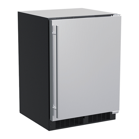
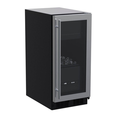
Marvel MLCP215-SS01B User manual

OWNER’S GUIDE & SERVICE MANUAL
MARVEL UNDERCOUNTER REFRIGERATION
Model: MLCP215-SS01B

WELCOME
Welcome to the Marvel Experience!
Congratulations on your purchase of the industry’s quietest
clear ice machine with the best ice clarity and purity. Your
new investment is protected by a limited warranty for the
rst year, and hermetically sealed refrigeration system parts
are covered for an additional 4 years.
Here’s your guide to the operation and maintenance of your
Marvel Clear Ice Machine to ensure years of enjoyment. If
you have any questions, please contact Marvel Customer
Service or Tech Support at:
Phone: (616) 754-5601
Email:
Got a Marvelous Design?
We would love to see how your Marvel product looks in its
new home. You can send us photos of your installed
might feature your Marvel home design on our website and
social media!
Warranty Registration
It is important you register your product warranty after
taking delivery of your appliance. You can register online at
www.marvelrefrigeration.com.
The following information will be
required when registering your
appliance:
Serial Number
Date of Purchase
Dealer’s name and address
The serial number can be found on the serial plate which is
located inside the cabinet on the left side near the top.
Online registration
available at
marvelrefrigeration.com

TABLE OF CONTENTS
Tip: Click on any section below to jump directly there
Safety
Important Safety Instructions
Installation
Unpacking Your Appliance
Electrical
Cutout & Product Dimensions
Side-by-Side & Stacking Installations
Door Reversal
Installing The Water Supply
Maintenance
Care and Cleaning
Long-Term Storage/Winterization
Operating Instructions
Using Your Electronic Control
Ice Maker Operation
Service
Obtaining Service
Troubleshooting
Wire Diagram
Product Liability
Warranty Claims
Ordering Replacement Parts
R600a Specifications
System Diagnosis Guide
Compressor Specifications
Control Operation - Service
Thermistor
Warranty
3

IMPORTANT SAFETY INSTRUCTIONS
Important Safety Instructions
Warnings and safety instructions appearing in this guide
are not meant to cover all possible conditions and
situations that may occur. Common sense, caution and
care must be exercised when installing, maintaining or
operating this appliance.
Recognize Safety Symbols,
Words and Labels
!WARNING
WARNING - You can be killed or seriously injured
if you do not follow these instructions.
!CAUTION
CAUTION -Hazards or unsafe practices which could
result in personal injury or property/product damage.
NOTE
NOTE -Important information to help assure a
problem-free installation and operation.
!WARNING
State of California Proposition 65 Warning:
This product contains one or more chemicals known
to the State of California to cause birth defects or
other reproductive harm.
!WARNING
State of California Proposition 65 Warning:
This product contains one or more chemicals known
to the State of California to cause cancer.
!WARNING
WARNING - This unit contains R600a (isobutane)
which is a ammable hydrocarbon. It is safe for
regular use. Do not use sharp objects to expedite
defrosting. Do not damage refrigerant circuit.
4

UNPACKING YOUR APPLIANCE
!WARNING
EXCESSIVE WEIGHT HAZARD
Use two or more people to move product.
Failure to do so can result in personal injury.
Remove Interior Packaging
Your appliance has been packed for shipment with all parts
that could be damaged by movement securely fastened.
Remove internal packing materials and any tape holding
internal components in place. The getting started guide is
shipped inside the product in a plastic bag along with the
warranty registration card and other accessory items.
Important
Keep your carton and packaging until your appliance has
been thoroughly inspected and found to be in good condi-
tion. If there is any damage, the packaging will be needed
as proof of damage in transit. Afterwards, please dispose of
all items responsibly.
!WARNING
WARNING - Dispose of the plastic bags which can
be a suocation hazard.
Note to Customer
This merchandise was carefully packed and thoroughly
inspected before leaving out facility. Responsibility for its
safe delivery was assumed by the retailer upon acceptance
of the shipment. Claims for loss or damage sustained in
transit must be made to the retailer.
DO NOT RETURN DAMAGED MERCHANDISE TO THE
MANUFACTURER - FILE THE CLAIM WITH THE
RETAILER.
NOTE
!CAUTION
If the appliance was shipped, handled or stored in other
than an upright position for any period of time, allow the
appliance to sit upright for a period of at least 24 hours
before plugging in. This will assure oil returns to the
compressor. Plugging the appliance in immediately may
cause damage to internal parts.
!WARNING
WARNING - Help Prevent Tragedies
Child entrapment and suocation are not problems of
the past. Junked or abandoned refrigerators are still
dangerous, even if they sit outside for “just a few hours”.
If you are getting rid of your old refrigerator, please
follow the instructions below to help prevent accidents.
Before you throw away your old refrigerator or freezer:
• Take o the doors or remove the drawers.
• Leave the shelves in place so children may not
easily climb inside.
5

ELECTRICAL
Do not remove
ground prong
!WARNING
Electrical Shock Hazard
• Do not use an extension cord with this appliance.
They can be hazardous and can degrade product
performance.
• This appliance should not, under any
• circumstances, be installed to an un-grounded
• electrical supply. Do not remove the grounding
prong from the power cord.
• Do not use an adapter.
• Do not splash or spray water from a hose on the
appliance. Doing so may cause an electrical shock,
which may result in severe injury or death.
Electrical Connection
A grounded 115 volt, 15 amp dedicated circuit is required.
This product is factory equipped with a power supply
cord that has a three-pronged, grounded plug. It must be
plugged into a mating grounding type receptacle in
accordance with the National Electrical Code and
applicable local codes and ordinances. If the circuit does
not have a grounding type receptacle, it is the responsibility
and obligation of the customer to provide the proper power
supply. The third-ground prong should not, under any
circumstances, be cut or removed.
NOTE
Ground Fault Circuit Interrupters (GFCI) are prone to
nuisance tripping which will cause the appliance to shut
down. GFCI’s are generally not used on circuits with power
equipment that must run unattended for long periods of
time, unles required to meet local building codes and
ordinances.
6

CUTOUT AND PRODUCT DIMENSIONS
ROUGH-IN OPENING DIMENSIONS CABINET DIMENSIONS
"A" "B" "C" "D" "E" "F" "G" "H" "J"
15"
(38.1 cm)
34" to 35"
(85.7 cm to 88.3 cm)
24"
(61 cm)
(37.8 cm)
(86.4 cm to 88.9 cm)
(60 cm)
1/2
(64.8cm)
(94.9 cm)
5/8
(42.2 cm)
Solid Door
Shown
"A"
"B"
"C"
"D"
"E"
If necessary, to gain clearance inside the rough-in
opening, a hole can be cut through the adjacent
cabinet and the power cord routed through this hole to
a power outlet. Another way to increase the available
opening depth is to recess the power outlet into the
rear wall to gain the thickness of the power cord plug.
Not all recessed outlet boxes will work for this applica-
tion as they are too narrow, but a recessed outlet box
equivalent to Arlington #DVFR1W is recommended for
this application.
7

CUTOUT AND PRODUCT DIMENSIONS
PRODUCT DATA
ELECTRICAL
REQUIREMENTS #
PRODUCT
WEIGHT
115V/60Hz/15A 105 lbs
(47.6 kg)
Minimum rough-in opening required is to be larger than the
adjusted height of the cabinet.
A grounded 15 amp dedicated circuit is required. Follow all
local building codes when installing electrical and
appliance.
Glass Door
Shown
"F"
2112"
(54.6 cm)
"D"
"E"
"H"
"J"
"G"
8

SIDE-BY-SIDE AND STACKING INSTALLATIONS
Side-by-Side Installation
Other Site Requirements
Units must operate from separate, properly grounded elec-
trical receptacles placed according to each unit's electrical
To ensure unobstructed door swing (opening both doors at
the same time), 1/4" (6.4 mm) of space needs to be maint-
ained between the units.
Hinge-by-Hinge Installation (Mullion)
When installing two units hinge-by-hinge, 13/16" (22 mm)
is required for integrated models. Additional space may be
needed for any knobs, pulls or handles installed.
Stainless steel models which include the standard stainless
handle will require 4-9/16" (116 mm) to allow both doors to
open to 90° at the same time.
Figure 10
Figure 11
Figure 12
Figure 13
Hinge-by-Wall Installation
When installing a unit hinge-by-wall or adjacent cabinetry,
7/16” (11mm) is required for integrated models. Additional
space may be needed for any knobs, pulls or handles installed.
¼”
13/16”
7/16”
4-9/16”
9

Door Reversing Instructions
Tools Needed:
• 1/8” Hex Key
• 5/32” Hex Key
• Phillips Screwdriver
Open door and remove Hinge Pin from the Upper Hinge using a 1/8” Hex Key tool making sure to steady the
Using a Phillips Screwdriver, remove the 6 screws from both the Upper and Lower Hinges and save for later steps
Once the Hinges are removed from the unit, using a Phillips Screwdriver, remove the Bushing Screw and Hinge Pin
Screw and save for later steps
On the Bottom Hinge, reattach the Bushing Screw and Hinge Pin Screw to the opposite side
Lower Hinge Bracket
(Before Reversal)
Upper Hinge Bracket
(After Reversal)
Lower Hinge Bracket
(After Reversal)
5. Using a 5/32” Hex Key, remove the Upper and Lower Hinge Brackets from the door saving all components.
screw into place
on the opposite side of the door (where plugs were removed). Remove the Cam Closer from the Lower-Hinge Bracket
and attach it to the opposite side
DOOR REVERSAL
Hinge Pin
Upper Right Hinge
Orientation
(Before Reversal)
Hinge Pin
Screw
Bushing
Screw
Lower Right Hinge
Orientation
(Before Reversal)
pper Left Hinge
Orientation
(After Reversal)
Upper Left Hinge
Orientation
(After Reversal)
Hinge
Bushing
Cam Closer
Upper Hinge Bracket
(Before Reversal)
10

6. Remove the door switch actuator tab from the door and attach it to the opposite side
DOOR REVERSAL
Door switch actuator tab
7. Reattach the Upper and Lower Hinges, and Hinge Brackets to opposite sides. Then install the door.
11

Control Function Guide
Function Command Notes
ON/OFF Press and release. Unit will immediately turn ON or OFF.
Toggle Interior Light - Door
Closed
Press and release to toggle interior light oper-
ation. Press again to deactivate. Light output 50%.
Enable Sabbath Mode Press and hold for 5 seconds and release.
The oF / oC symbol will fl ash briefl y after 5 seconds. Interior
light and display will go dark and remain so until user resets
mode - unit continues to operate.
Disable Sabbath Mode Press and release. Display and interior light return to normal operation.
Silent Mode (ice production
suspended for 3 hours) Hold and . Display will count down the hours:
Clean Mode Hold for 10 seconds to begin clean cycle. Unit will return to normal operation upon completion of clean-
ing. See “Care and Cleaning” section for more information.
Showroom Mode Hold and for 5 seconds.
The oF / oC symbol will fl ash. Display will be lit and interior light
will function. Unit will not cool. Repeat command to return to
normal operation.
Door Alert Notifi cation
When the door is left open for more than 30 minutes:
• A tone will sound for several seconds every minute
• will appear in display
• Close door to silence alert and reset
will appear in display
First Use
Initial startup requires no adjustments. When plugged in, the unit will
begin operating under the factory default settings. If the unit was turned off
during installation, simply press and the unit will immediately switch on.
To turn the unit off , press .
Electronic Control
Hold for 10 seconds to begin clean cycle.
USING YOUR ELECTRONIC CONTROL
12

ionized water are not recommended as they can adversely
Water
Supply
Line
Clamp and
Screw
Back view of
ice machine
NOTE
!CAUTION
INSTALLING THE WATER SUPPLY
Compression
Water
supply
line
Water supply
service loop
valve
Water valve
inlet
Water Supply
Observe and follow all local building codes when installing
this appliance.
This ice machine must be connected to a potable cold
water supply line. delivering water pressure between a
minimum of 20 psi and a maximum of 120 psi.
Use 1/4" copper tubing for your water supply which is
available at any local hardware or plumbing supply store.
Route the 1/4" copper tubing to suit your installation being
sure not to kink the tubing. Purchase enough copper tubing
length to allow a coil to be formed behind the unit for a
"service loop" which will allow the appliance to be pulled
out from the installation for servicing or cleaning. Connect
the copper tubing to the "top side" of a cold water pipe to
prevent the ice-maker from plugging with sediment.
ease servicing the appliance. NOTE: A SELF-PIERCING
TYPE VALVE IS NOT RECOMMENDED as they are prone
to clogging with sediment which will create pressure drop
reducing the water supply to the unit.
Connect the copper tubing water supply to the water valve
IMPORTANT: Secure the water supply line to the back of
the cabinet with the screw and strain relief clamp provided
in the corner of the back panel.
Make certain all connections are watertight after
installation. Form the tubing so that it will not vibrate
against the cabinet body or kink when your appliance is
moved in and out of position.
This ice machine is designed to make clear ice from the
majority of water sources on a daily basis. If your results
treated. A water specialist can recommend proper water
treatment.
!CAUTION
•
only. Do not use with plastic tubing.
•
13

The Ice Making Process
fractional freezing to form a slab of ice that is clear and
has less dissolved solids than the water it is produced
from. This is accomplished by running water over the cold
evaporator plate which gradually freezes
leaving the
dissolved solids in the residual reservoir water to provide
clear ice.
sheet is released and slides onto the grid cutter
cutter’s heated
wires. The water containing the dissolved minerals is
drained after each freezing cycle. Fresh water enters the
machine for the next ice making cycle.
Water distributor
Water
reservoir
Evaporator
Circulation
Pump
Reservoir
drain plug
Front
panel
Bin Level
Sensor
Ice
Grid Cutter
ICE MAKER OPERATION
14

when the ice supply is low or full and starts or stops the ice
making process accordingly.
power to the unit.
New Sounds
your household refrigerator. Because these sounds are
new to you they may be of a concern but are most likely
normal. The ice production process will make noises that
valves opening and closing. Following are some of the
A buzzing sound will be heard when the water valve
water line.
evaporator plate and into the water reservoir.
A "thud" when the ice slab is released from the
evaporator plate and slides onto the grid cutter.
"Clicks" when the cubes fall into the ice storage bin.
machine.
An air noise from the condenser fan.
Ice Production
In normal mode the ice machine will produce up to 39
pounds (17.7 kg) of clear ice in a 24-hour period when
installed in a 72°F ambient with a 55°F water supply.
24-hours of operation the unit will produce up to 39 lbs of
the ice storage bin is maintained at a temperature slightly
production rate will overcome the ice melt and the storage
NOTE
NOTE
The ice machine will keep producing ice until the ice
machine’s bin is full and will restart automatically when
ice needs to be replenished in the bin. The ice bin is
machine to run for 24-48 hours to accumulate ice in the ice
machine’s bin.
ICE MAKER OPERATION
15

!CAUTION
Forcing ice through the grid cutter will break the grid cutter
wires.
!CAUTION
Remove all ice
from the evaporator
plate and grid cutter
area that is not
embedded in wires
Clean reminder: CLEAN
NOTE
OFF
dependent on
your water source and usage. Normal ice production will
continue while the "CLEAN" reminder is displayed.
When
another
. If you choose to clean the appliance at
Clean mode:
recommended to clean your ice machine once every six
months. This simple cleaning routine will also ensure
water
Once you have your cleaner:
the
"ON/OFF" icon for 3 seconds. "OFF" will be displayed on
the control.
Use only Marvel-approved ice machine cleaner and follow
all label warnings and directions. Incorrect chemical
warranty.
To clean your ice machine you will need to purchase a
"nickel safe" ice maker cleaner. You can order ice machine
cleaner (part # S41013789) at marvelrefrigeration.com.
machine is ready to be cleaned.
While cleaning is needed, UI will alternate between "CL"
and "ICE" every 3000 cycles to indicate that the unit needs
to be cleaned. Over time, mineral build-up on the cold
evaporator plate can occur which can adversely affect the
quality of your ice. This build-up is dependent on your
water source and usage. Normal ice production will
continue while the "CLEAN" reminder is displayed. The
"CL" clean reminder will reset after your ice machine has
completed the cleaning cycle and will not occur for another
3000 cycles.
16

CARE AND CLEANING
Remove all of
the ice from
the ice bin
Remove the
black reservoir
drain plug from
the bottom of
the reservoir.
Splash shield
brackets
After the cleaning cycle is completed, verify that all build-up
has been removed. If not, repeat the clean cycle procedure.
Clean inside of unit with a clean, damp rag before ice mak-
ing cycle begins.
Replace the splash shield if removed.
Clean cycle time is approximately 45 minutes.
Ice maker will automatically return to ice making once clean
cycle is complete.
Pour cleaning solution slowly
onto the front edge of evaporator
plate behind the grid cutter.
Evaporator
plate
Grid cutter
Splash shield
Lift fascia door up to ac-
cess evaporator plate
Remove ice from bin. Pull plug from the reservoir. Once
reservoir is empty, replace plug. Hold the button for
10 seconds to show "CL" on the display. Lift Fascia door
to access evaporator plate. Lift or remove splash shield to
expose evaporator plate. Using 1-3 ounces of cleaner,
pour cleaning solution slowly on evaporator plate so it
flows down into the fresh water reservoir.
17

18

Draining and Removing Water from the Ice-
Making System with a Gravity Drain.
1.
2.
3.
water valve.
Change the electronic control to the "CLEAN" position
for approximately one (1) minute. This will energize and
open the water valve and remove most of the water
from the water valve and the water valve’s outlet water
line to the reservoir.
4. Change the electronic control to the "OFF" position.
This will energize and open the drain valve to drain the
reservoir and the ice machine drain system.
5. Unplug the ice machine from the electrical outlet.
6. Remove the access cover from the rear of the ice
machine.
water in the ice-making system.
This ice machine must have all water drained and removed
to prevent ice machine damage as well as possible water
damage to the surrounding area in freezing conditions.
These damages are not covered under warranty.
Do not use any type of anti-freeze or other solution as a
substitution for properly draining the ice machine.
Clean the Ice Machine
Cleaning the ice machine will help prevent mold and
mildew growth as well as sanitize the ice machine for
storage or when it is put back into service.
!CAUTION
!CAUTION
Risk of electrical shock or personal injury could occur
access cover is removed before unplugging the ice
machine.
!WARNING
Electrocution Hazard
Back view of
ice machine
Water supply
Water
supply
line
Water valve
inlet
Access
cover
Screw
!CAUTION
Winterization: If the unit will be exposed to temperatures
LONG TERM STORAGE AND WINTERIZATION
19

Reconnect the water valve outlet water line.
Reinstall the ice machine’s access cover.
Clean and dry the ice machine’s storage bin.
Prop the door open for air circulation to prevent mold
and mildew.
Leave the water supply line disconnected or
reconnect
water on and allow water to enter back into the
water valve.
White
collar
Plastic outlet
water line
7. Disconnect the water valve’s outlet water line to the
reservoir and drain the remaining water left in the water
line trap area.
To disconnect the water outlet
line: Push up on the white collar
and pull the plastic water line
from the bottom of the water
valve.
To reconnect the water outlet
line: Simply insert the plastic
tubing into the white collar and
push until it stops (about 12
valve).
Draining Water for Factory Installed Drain
Pump Applications
Follow steps 1 through 12 for the gravity drain then do the
13. Install the winterization plug in the water drain hole
inside the ice bin.
Winterization
plug
LONG TERM STORAGE AND WINTERIZATION
20
Table of contents
Other Marvel Refrigerator manuals
Marvel
Marvel 60RD-BB-F User manual
Marvel
Marvel MS15RA Manual
Marvel
Marvel 60HK-SS-F Guide
Marvel
Marvel 8SBARE Manual
Marvel
Marvel 60RD Guide
Marvel
Marvel 30AR-BB-F User manual
Marvel
Marvel MPWC424-SG31A User manual
Marvel
Marvel 60RGD-SS-F Manual

Marvel
Marvel MORF224 User manual
Marvel
Marvel 3BAR-BD User manual
Marvel
Marvel MS24FASFRW Manual

Marvel
Marvel MOKR124-SSD1A User manual

Marvel
Marvel MLRE024 User manual
Marvel
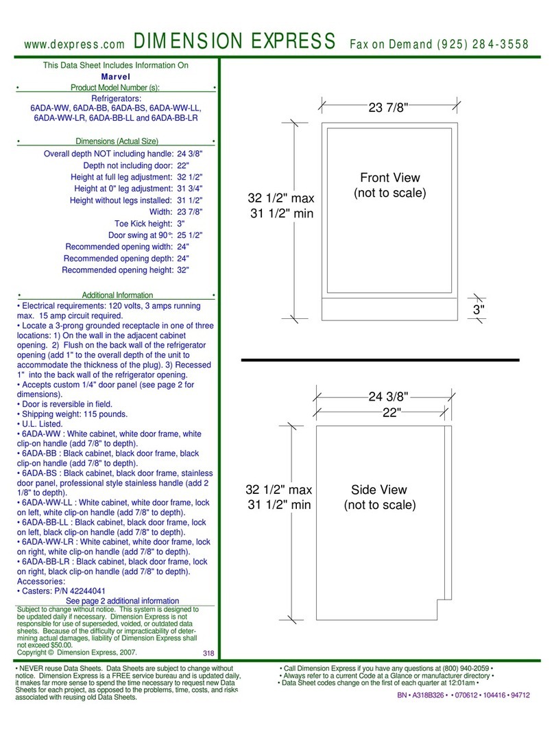
Marvel 6ADA-BB User manual
Marvel
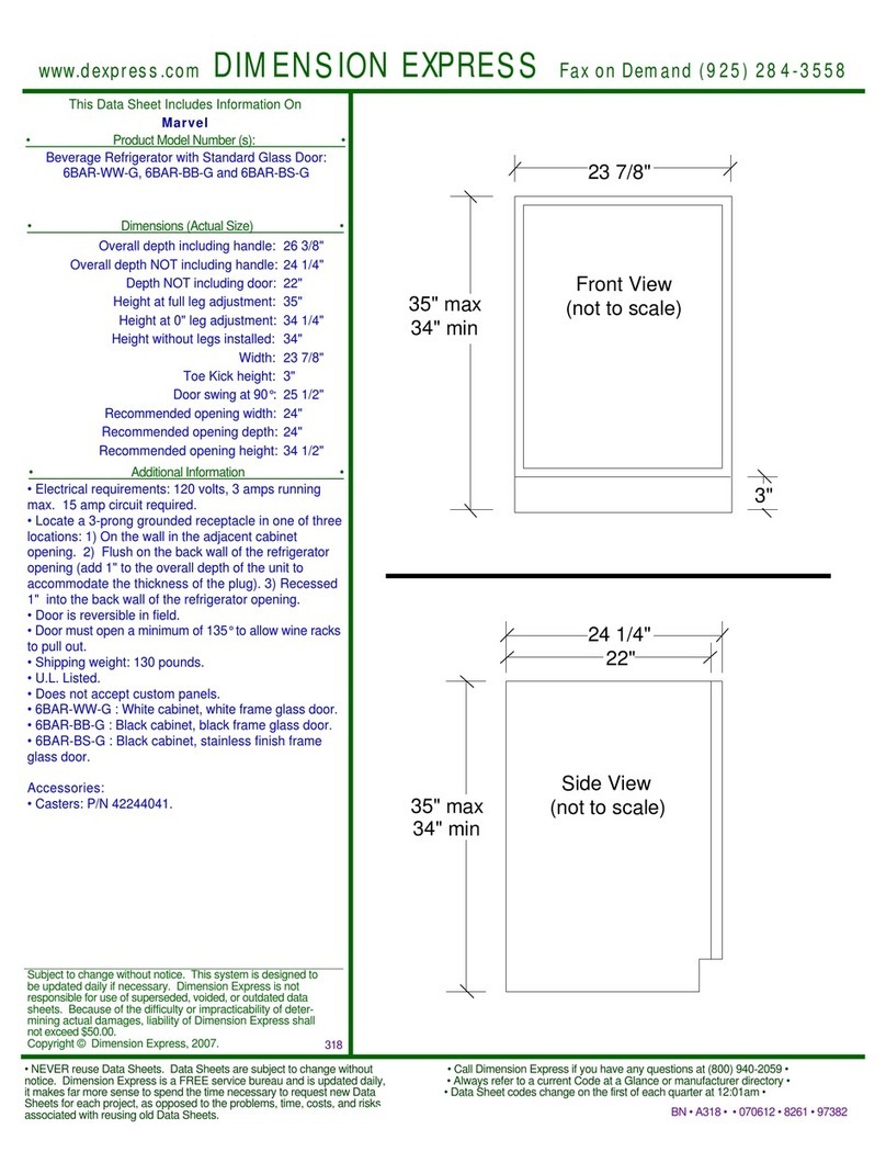
Marvel 6BAR-BB-G User manual
Marvel
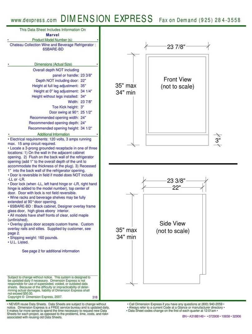
Marvel 6SBARE-BD User manual
Marvel
Marvel 4570105 User manual
Marvel
Marvel MPRE424-SG81A User manual
Marvel
Marvel MLCP215 User manual
Marvel
Marvel MPWD424-SS31A User manual

