MAS 640 Series User manual

MAS 640 Instruction Manual Rev. 0A
MAS 640
Instruction Manual
MAS Advanced Measurement Solutions
www.massensors.com
-1-

MAS 640 Instruction Manual Rev. 0A
Table of Contents
1. Introduction........................................................................................................................................................3
2. Specification.......................................................................................................................................................3
2.1. General Technical Data ...................................................................................................................3
Figure 2: Mounting holes distance in mm ....................................................................................................
2.2. Applications.............................................................................................................................................
2.3. Technical Data A/D Converter...................................................................................................................
3. Putting Into Operation........................................................................................................................................5
3.1. Opening the Instrument..............................................................................................................................5
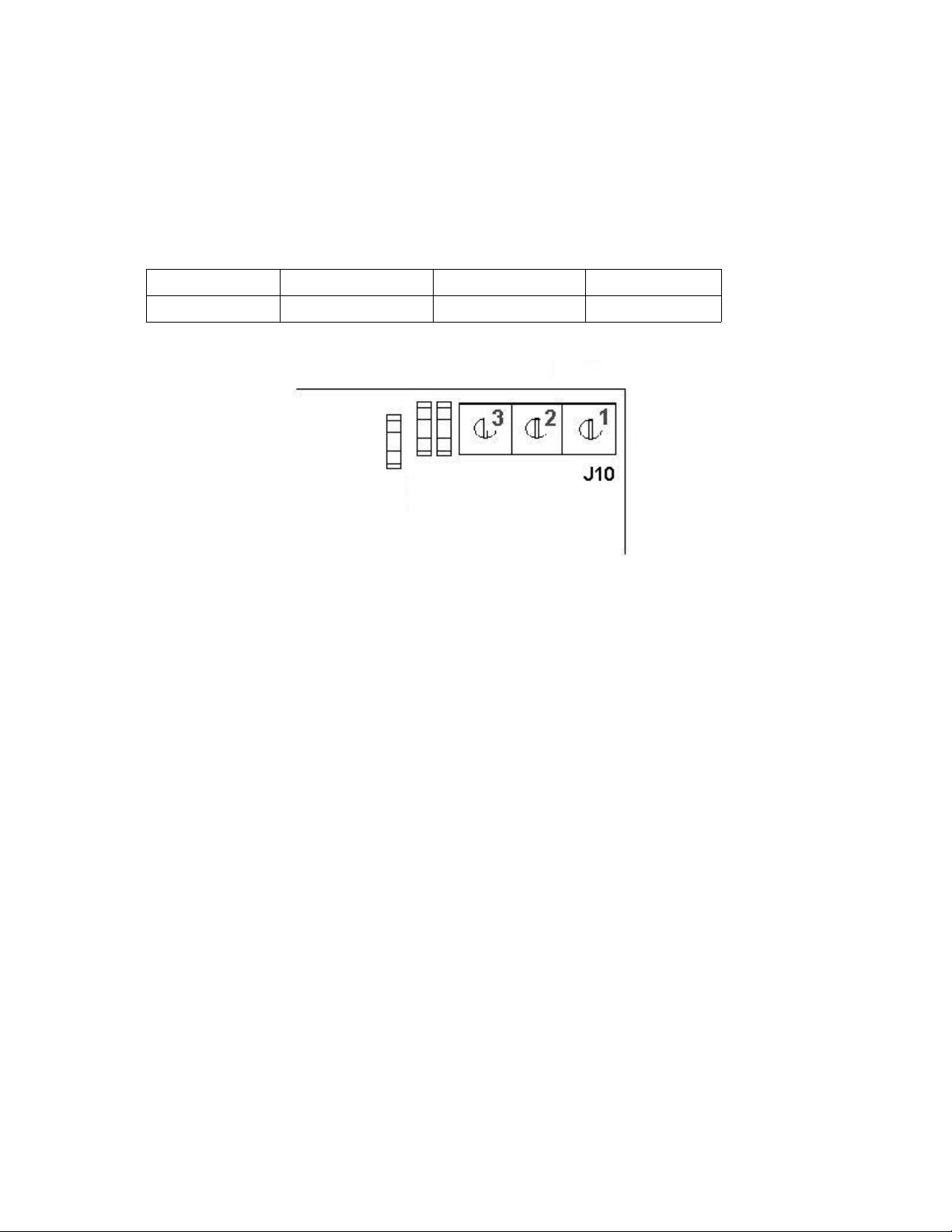
3.2. Connecting a Weighing Platform...............................................................................................................5
3.3. Connecting to the Serial Interface .............................................................................................................6
. Basic Functions..................................................................................................................................................7
.1. User Interface............................................................................................................................................7
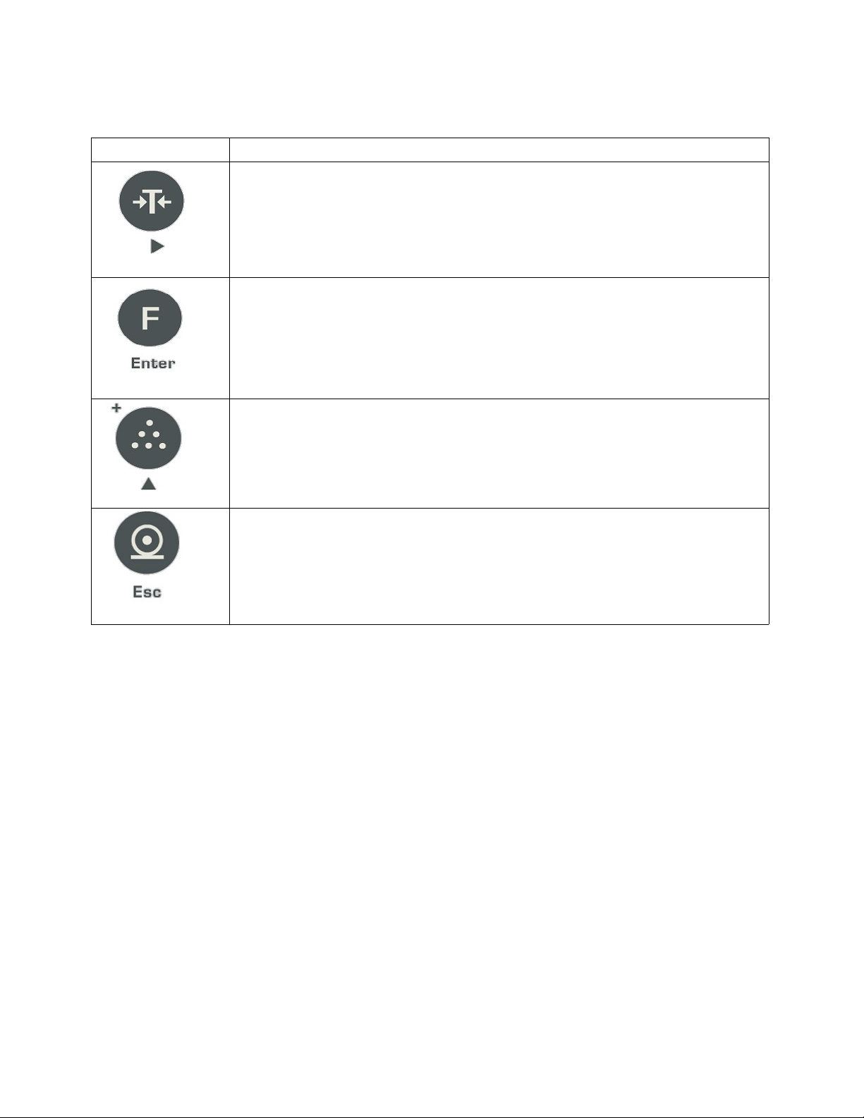
.2. Operation Keys .........................................................................................................................................7
.3. Note on Stability ........................................................................................................................................8
. . Front Panel Annunciators (LEDs)..............................................................................................................9
.5. Switching the Instrument On and Off.........................................................................................................9
.6. Zeroing.......................................................................................................................................................9
.7. Simple Weighing........................................................................................................................................9
.8. Weighing with Tare..................................................................................................................................10
.9. Printing/transferring data..........................................................................................................................10
5. Special Functions.............................................................................................................................................10
5.1. Special Function Keys..............................................................................................................................10
5.2. Counting...................................................................................................................................................10
5.3. Setting a Filtering Level...........................................................................................................................11
5. . Accumulate Weighing..............................................................................................................................11
5.5. Printout Select....................................................................................................................................11
5.5.1. Printout Select Options....................................................................................................................12
5.6.1. Autozero/Zero Tracking Options...........................................................................................................13
6. Setup................................................................................................................................................................13
6.1. Entering the Setup Mode.........................................................................................................................13
6.2. Main Menu Setup Functions....................................................................................................................1
6.2.1. Switching Between the Setup Functions from Main Menu..............................................................1
6.2.2. Editing Function Content..................................................................................................................15
6.2.3. Accepting or Canceling Changes ....................................................................................................15
6.3. Example Setup Table for Single Interval Weight Measurements............................................................16
6. . Example Setup Table for Two Interval Weight Measurements................................................................16
7. Calibration Routines ........................................................................................................................................17
7.1. Zero Calibration.......................................................................................................................................17
7.2. Span Calibration......................................................................................................................................18
8. Saving Changes...............................................................................................................................................19
9. Leaving Setup mode .....................................................................................................................................19
10. Error Messages Table....................................................................................................................................19
-2-

MAS 640 Instruction Manual Rev. 0A
1. Introduction
The weight indicator MAS 6 0SS was designed for fast and accurate high resolution measurements. Its
performance is based on a 2 bit delta sigma A/D converter. Water resistant housing allows this instrument to
work under very demanding industrial environments with years of constant quality.
This manual provides technical specification as well as instructions for setup and use of the instrument.
2. Specification
2.1. General Technical Data
Main display 7 segment LED display, 6 numbers, 20 mm high
Housing ABS plastic, protection class IP66
Power Supply Power adapter 12-15V DC
Data Interface RS232
Operating Temperature -10°C... + 0 °C
Storage Temperature -20°C...+60 °C
Relative Humidity 10...85 %, non condensing
Weight Approx 1 kg
Figure 1: Case dimmensions in mm.
-3-

MAS 640 Instruction Manual Rev. 0A
Figure 2: Mounting holes distance in mm
2.2. Applications
Weighing functions
● Simple weighing
● Check weighing
● Zero setting, Zero tracking, Autozero
● Taring, Clearing tare
● Counting
● Totalization
Optional functions ● Barcode printer connection
● Barcode scanner connection
● AC relay/DC relay output
● 0-10V output
● -20 mA output
2.3. Technical Data A/D Converter
Load Cell Excitation Voltage +5V DC
Load Cell Drive Up to 8 x 350 Ohm load cells
Maximum Displayed Resolution 1 : 60.000 d
Measurement Update Rate 10 Hz
Loadcell Input Sensitivity Up to 3mV/V
- -

MAS 640 Instruction Manual Rev. 0A
3. Puttin Into Operation
3.1. Openin the Instrument
WARNING!
Before opening the instrument disconnect the power cord from the power supply.
To open the instrument unscrew the 8 screws from the back and lift the cover.
3.2. Connectin a Wei hin Platform
●Insert the weighing platform cable into the instrument through the cable gland
●Connect the weighing platform cable to J3 terminal according to the
table below.
Pin 1 2 3 5 6
Assignment SIG+ SIG- EXC+ EXC- REF+ REF-
Note:
For wire loadcells J1 and J2 pads should be solder bridged or Ref+ and Ref- shoud be connected to EX+
and EX- respectively.
Figure 2: Location of J3 terminal on the digital module inside the instrument.
-5-

MAS 640 Instruction Manual Rev. 0A
3.3. Connectin to the Serial Interface
●Insert the interface cable into the instrument through the cable gland.
●Connect the interface cable to the J10 (3-pin terminal) according to the table below.
Pin 3 2 1
Assignment Rxd Gnd Txd
Figure 3: Location of J10 terminal on the digital module inside the instrument.
Default parameters are: 800 bps, 8 data bits, no parity, one stop bit, no handshake.
-6-

MAS 640 Instruction Manual Rev. 0A
4. Basic Functions
4.1. User Interface
Figure 5. Front panel interface
4.2. Operation Keys
KEY DESCRIPTION
<POWER>
The <POWER> key is used to turn the instrument on and off.
<ZERO>
The <ZERO> key is used to execute zero level adjustment.
Use the <ZERO> key once empty scale has drifted away from zero reading.
-7-

MAS 640 Instruction Manual Rev. 0A
<TARE>
The <TARE> key is used to display zero on the display when an empty container is
placed on the weighing platform.
Use the <TARE> key to cancel mass of an empty container
<FUNCTION>
The <FUNCTION> key is used to select one of the special function. Refer to the
Special Functions [ section 5.] for the details on the available functions.
<PIECES> The <PIECES> key activates counting pieces of similar weight like screws,
nails, etc.
A long press of the <PIECES> key is used to declare the number of sample pieces
used as a reference for counting. For more details on how to use this function refer to
the Special Functions [ section 5.].
<PRINT>
The <PRINT> key sends the current status to a connected printer allowing a printout
of the displayed stable readings, i.e. weight, total weight, number of pieces.
Please note, readings must be stable on the display before printing.
4.3. Note on Stability
The Unit has to wait for stable readings when the <ZERO>, <TARE> or <PRINT> key is pressed.
That way execution of associated operation may be delayed by a few seconds. Readings are stable when you
see the LED of stable reading symbol [section . ] highlited.
If readings are unstable for more than 10 seconds message error -E06- will be displayed and printing
operation will be canceled.
-8-

MAS 640 Instruction Manual Rev. 0A
4.4. Front Panel Annunciators (LEDs)
Symbols on the
front panel
Description
I, II Indicates which one of two ranges is actually in operation
ƩIndicates that total weight is being displayed
Indicates stable readings for weighing or counting
k , lb Indicates unit of weight measurements
pcs Indicates that the instrument is working in counting pieces mode
zero Indicates that instrument is at zero reference level
net Indicates that Net values are being displayed
Indicates the standby mode
4.5. Switchin the Instrument On and Off
Press the <POWER> key to turn on the instrument.
The display lights up, serial number appears and the instrument performing a self test.
Press the <POWER> key once instrument is in the operation to switch to the standby mode.
The standby mode is indicated by the standby LED.
Warnin :
While in the standby mode the instrument is still connected to AC mains power supply. During the
maintenance disconnect instrument's power supply plug from the wall socket.
4.6. Zeroin
Unload weighing platform.
Press the <ZERO>key.
Zero level is indicated by lighting up the zero LED placed just above the <ZERO> key.
4.7. Simple Wei hin
Press the <ZERO> key to light up zero annunciator if needed.
Place the weighing sample on the weighing platform.
Wait until stab. annunciator is on.
Read weighing result.
-9-

MAS 640 Instruction Manual Rev. 0A
4.8. Wei hin with Tare
Place the empty container on the weighing platform and press the <TARE> key. Instrument will cancel a
container mass by displaying zero.
On the main display, after canceling a container mass, the net LED will light up just above the <TARE>
key to indicate the Net weight readings.
To cancel tare effect press the <TARE> key once instrument's readings are zero or below zero.
4.9. Printin /transferrin data
Press the <PRINT> key.
The display contents are printed out or transferred to a computer.
Refer to the section 5.5 for the available printout options.
Note:
Unstable readings will not be printed out or transfered to a computer.
5. Special Functions
5.1. Special Function Keys
Special functions are accesed through the Operation Keys.
Follow the symbol under each Operation Key to recognize its additional function.
5.2. Countin
Place the container on the weighing platform and press the <TARE> key if needed.
Place the known number of sample pieces to be counted into the container.
Note: The greater sample number and weight, the more accurate are the counting results.
A long press the <PIECES> key, then set the number of sample pieces to be loaded with the <TARE>,
<ZERO> or <PIECES> keys, according to the arrow markings under each key.
Accept changes by pressing the <FUNCTION> key.
Read the number of peaces after stab annunciator lit.
To exit counting mode short press the <PIECES> key. Unit will go back to the weighing mode.
Note: Once the number of sample pieces is stored by the unit memory there is no need to load the sample
pieces again until a different item is to be counted.
User can simply toggle between counting mode and weighing mode by short pressing the <PIECES> key.
If there is no sufficient load of sample pieces during counting mode unit displays the message error -E08-.
-10-

MAS 640 Instruction Manual Rev. 0A
5.3. Settin a Filterin Level
Press the <FUNCTION> key.
Press the <PIECES> key repeatedly until message 'AuE' displayed.
Press the <FUNCTION> key to enter filtering sub menu.
Change the last digit blinking from 0 to 3 to adjust strenght of the filter.
Accept changes by pressing the <FUNCTION> key.
Filtering Level: Description:
0 background FIR filtering
1 mild average
2 strong average
3 very strong average
5.4. Accumulate Wei hin
Press the <FUNCTION> key.
Press the<PIECES> key repeatedly until message totAL displayed.
Press the<FUNCTION> key to enter Accumulate Weighing sub menu.
Change the last digit blinking to 0 or 1 to disable or enable Accumulate Weighing respectively.
Accept changes by pressing the <FUNCTION> key.
5.5. Printout Select
Press the <FUNCTION> key.
Press the <PIECES> key repeatedly until message 'SE' displayed.
Press the <FUNCTION> key to enter Printout Select sub menu.
Change the last digit blinking for 1,2,3 or with the <PIECES> key. Refer to the Printout Select Options'
table [5.5.1] for more information.
Accept changes by pressing the <FUNCTION> key.
-11-

MAS 640 Instruction Manual Rev. 0A
5.5.1. Printout Select Options.
No Description
1 Net weight only printout.
Example:
N: 12. kg
2 Net and Gross weight printout.
Example:
N:12. kg
G:13.0 kg
3 Net, Gross and Tare weight printout .
Example:
N: 12. kg
G: 13.0 kg
T: 0.6 kg
Net weight and Total weight printout .
Example:
N: 12. kg
SUM: 12. kg
---------------------------- #1
N: 12.0 kg
SUM: 2 . kg
---------------------------- #2
N: 10.1 kg
SUM: 3 .5 kg
---------------------------- #3
5...9 Label printout (option).
5.6. Autozero / Zero Trackin Select
●Press the <FUNCTION> key.
●Press the <PIECES> key repeatedly until message 'AZEr' displayed.
●Press the <FUNCTION> key to enter Autozero/Zero Tracking Select sub menu.
●Change the last digit blinking for 0,1 or 2 with the <PIECES> key. Refer to Autozero/Zero Tracking
Options table [5.6.1] for more information.
●Accept changes by pressing the <FUNCTION> key.
-12-

MAS 640 Instruction Manual Rev. 0A
5.6.1. Autozero/Zero Trackin Options
Autozero option No. Description:
0 Disable Autozero and Zero tracking
1 Enable Zero tracking only
2 Enable Zero tracking and Autozero
6. Setup
6.1. Enterin the Setup Mode
To enter the setup mode:
●Disconnect the indicator from the power supply.
●Remove the instrument back cover. Move the jumper on the digital module from the position J9 to J8
[Figure 5.].
●Turn the power on.
●Once display shows the 'iuPER' message, move the jumper on the digital module from the position J8
to J9.
Display will light 'SET' message as shown. Now you can select any function from Main Manu Setup Functions
[6.2.] by pressing repeatedly the <PIECES> key.
Figure 5: Location of the J8, J9 jumpers on the digital module inside the instrument.
-13-

MAS 640 Instruction Manual Rev. 0A
6.2. Main Menu Setup Functions
See the Table below for available functions.
Firmware version A0.01
Function name Description
dP Setting position of decimal point for display readings.
Allowed numbers: 0 to 3.
0 – no decimal point.
1,2,3 – n position from right end of the display.
Example:
Dp = 3; the display zero reading is: 0.000
Dp = 2; the display zero reading is: 0.00
di1 Value of the least significant digit for the first interval.
Allowed numbers : 1,2,5,10,20,50.
Example:
Once di =1 is chosen, every reading in the least significant position of the
displayed value will be changed by 1.
Once di = 5 is chosen, every reading in the least significant position of the
displayed value will be changed by 5, etc.
di2 Value of the least significant digit for the second interval see description for di1
function.
FU1 Setting the maximum value for the first measuring interval.
Maximum allowed number is 99999.
FU2 Setting the maximum value for the second measuring interval.
Maximum allowed number is 99999.
ESetting the value of the load the unit will be adjusting (calibrating) with. Maximum
allowed number is 99999.
E should be no more than value at FU2.
ZErOCAL No load calibration. This level will be recognized by the instrument as a zero
reference.
SPAnCAL Span calibration at a load declared in E function
SAuE Savings parameters to nonvolatile memory.
6.2.1. Switchin Between the Setup Functions from Main Menu
To switch between the different functions of the Main Menu press the <PIECES> key
repeatedly.
< PIECES>
-1 -

MAS 640 Instruction Manual Rev. 0A
6.2.2. Editin Function Content
To edit content of a chosen function press the <FUNCTION> key while function
name is displayed.
The flashing digit and the function name will light on the display.
<FUNCTION>
To change the content of a chosen function use the <PIECES> key to increment the
value of the flashing digit.
<PIECES>
Use the <ZERO> or <TARE> keys to move the flashing digit position to the left or
right respectively.
<ZERO>
<TARE>
6.2.3. Acceptin or Cancelin Chan es
To accept the changes press the <FUNCTION> key and chose another function
from the Main Menu.
<FUNCTION>
Press the <PRINT> key to cancel any changes within chosen function and go back to
the Main Menu.
<PRINT>
-15-

MAS 640 Instruction Manual Rev. 0A
6.3. Example Setup Table for Sin le Interval Wei ht Measurements
Max
Cap[k ]
n d dP diu div2 FU1 FU2 E<=FU2
(example value)
1 10000 0.1g 1 1 1 10000 10000 10000
3 6000 0.5g 1 5 5 30000 30000 30000
6 3000 2g 0 2 2 6000 6000 6000
15 3000 5g 3 5 5 15000 15000 10000
30 3000 10g 2 1 1 3000 3000 2000
60 3000 20g 2 2 2 6000 6000 6000
150 3000 50g 2 5 5 15000 15000 10000
300 3000 100g 1 1 1 3000 3000 1500
600 3000 200g 1 2 2 6000 6000 3000
1500 3000 500g 1 5 5 15000 15000 1000
3000 3000 1kg 0 1 1 3000 3000 2000
6.4. Example Setup Table for Two Interval Wei ht Measurements
Max
Cap[k ]
n* d dP diu div2 FU1 FU2 E <= FU2
(example value)
3/6 6000 1g/2g 0 1 2 3000 6000 6000
6/15 7500 2g/5g 0 2 5 6000 15000 10000
15/30 6000 5g/10g 0 5 10 15000 30000 15000
30/60 6000 10g/20g 2 1 2 3000 6000 10000
60/150 7500 20g/50g 2 2 5 6000 15000 10000
150/300 6000 50g/100g 1 5 10 15000 30000 15000
300/600 6000 100g/200g 1 1 2 3000 6000 3000
1500/3000 7500 500g/1000g 1 5 10 15000 30000 15000
•scale intervals
-16-

MAS 640 Instruction Manual Rev. 0A
7. Calibration Routines
7.1. Zero Calibration
After entering the setup mode [section 6.1] repeatedly press the <PIECES> key
until ZerCAL is displayed.
< PIECES>
Make sure that there is no load at the weighing platform.
Press the <FUNCTION> key. ZerCAL will start to flash.
Press the <FUNCTION> key again and the calibration will start.
<FUNCTION>
During the calibration the display shows the internal count reading at the zero level.
Once the reading is stable you can accept it by pressing the <FUNCTION> key. <FUNCTION>
Wait until program return to the main menu setup displaying ZerCal. Press the
<PIECES> key to select another function from the main menu setup.
<PIECES>
-17-

MAS 640 Instruction Manual Rev. 0A
7.2. Span Calibration
After entering the setup mode [see 6.1] repeatedly press the <PIECES> key until
SPAn is displayed. <PIECES>
Make sure the weighing platform is loaded by a load of weight declared in the E
function of the main menu.
Press the <FUNCTION> key. SPAn will start to flash. Press the <FUNCTION> key
again and span calibration will start. <FUNCTION>
During the calibrtion the display shows the internal count reading at the span level.
Once the reading is stable accept it by pressing the <FUNCTION> key.
<FUNCTION>
Wait until the program return to the main menu displaying SPAn and
press the <PIECES> key to select another function from the main menu.
<PIECES>
-18-

MAS 640 Instruction Manual Rev. 0A
8. Savin Chan es
In the main menu setup, press the <PIECES> key repeatedly until 'SauE' is
displayed.
< PIECES>
Accept the savings by pressing the <FUNCTION> key.
<FUNCTION>
9. Leavin Setup mode
After completion of all the adjustments select the 'SAuE' function from the main menu and accept it by pressing
the <FUNCTION> key.
●Make sure the calibration jumper is in the position J10.
●Power cycle the instrument.
Warnin :
New settings will not be stored unless saved in non volatile memory
10. Error Messa es Table
Error: Description: Solution:
-E06- The readings are not stable. Retry an operation when the readings
become stable.
-E07- The initial load exceeds 10% of the
maximum range.
Remove any load from the platform before
turning on the instrument.
-E08- Counting pieces resolution error occurred. For the counting mode, mass of the single
piece should represent at least 1/ of the
instrument minimum displayed division. Use
heavier item for counting.
-E02- Load exceeds the maximum measuring
range of the instrument.
Remove heavy load from the platform.
-E01- Incorrect tare value occured. Taring is only allowed for indication higher
than zero.
Use the<Tare> key to clear the previous tare
while indication is below or equal to zero.
-19-

MAS 640 Instruction Manual Rev. 0A
NOTES:
-20-
This manual suits for next models
1
Table of contents