Qimarox PRORUNNER Mk5 User manual

Prorunner mk5
User Manual
2.0 / 2019-12-12

Qimarox
Nobelstraat 43
3846 CE Harderwijk
The Netherlands
Tel: +31 341 436 700
Fax: +31 341 436 701
E-mail: [email protected]
Internet: www.Qimarox.com
Copyright © Qimarox B.V.
All rights reserved. No part of this publication may be reproduced, stored in a computer
database or published in any form or in any way electronically, mechanically, by means of
photocopying, recordings or in any manner without prior written permission from Qimarox.
2 UM-Prorunner mk5-2.0-EN

Table of Contents
1 About this manual
1.1 Introduction...............................................................................................................................6
1.2 Product documentation............................................................................................................ 6
1.3 Source language...................................................................................................................... 7
1.4 Drawings.................................................................................................................................. 7
1.5 Symbols used in the manual.................................................................................................... 7
1.6 Terminology list.........................................................................................................................7
1.7 Further support and information............................................................................................... 8
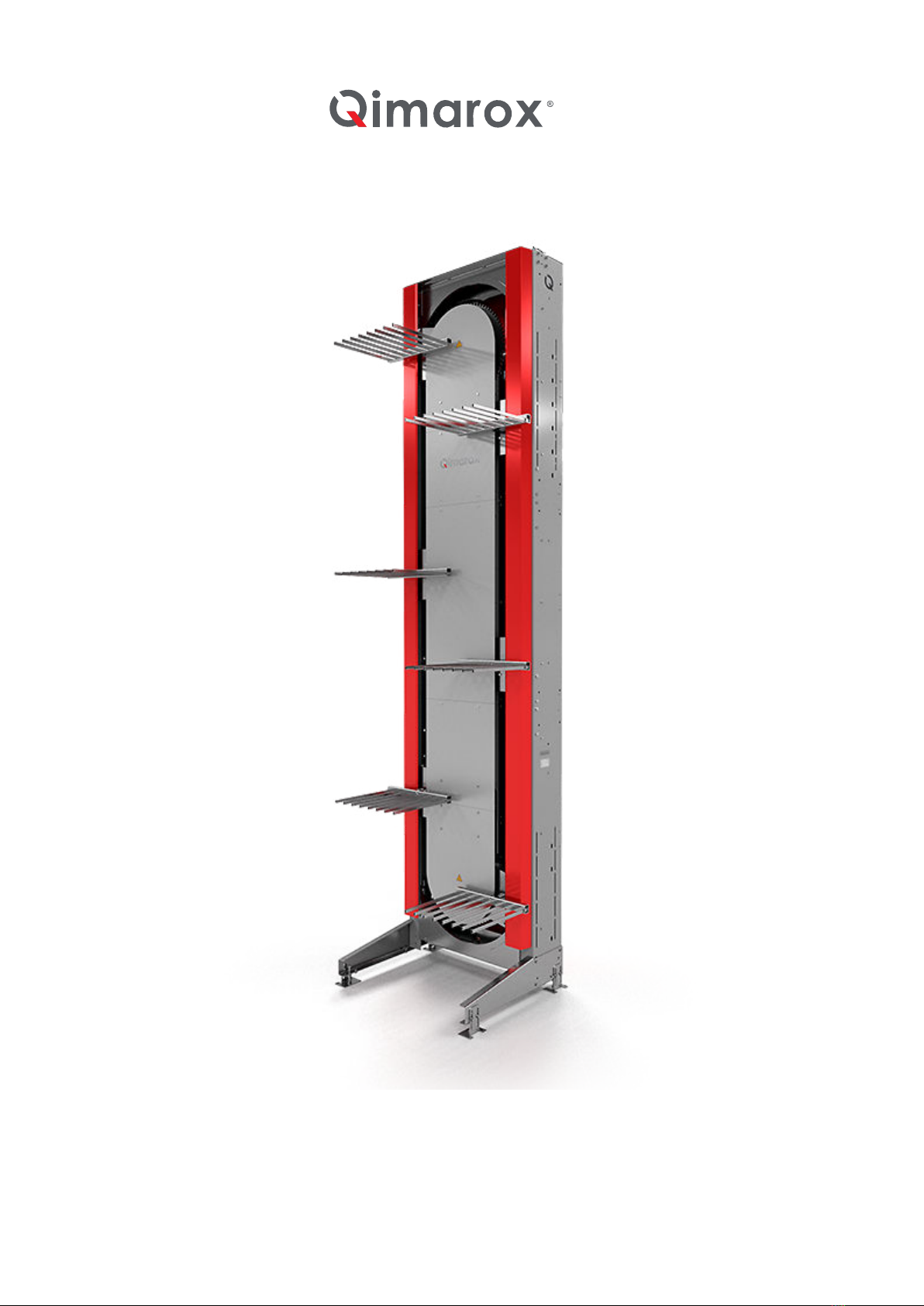
2 General
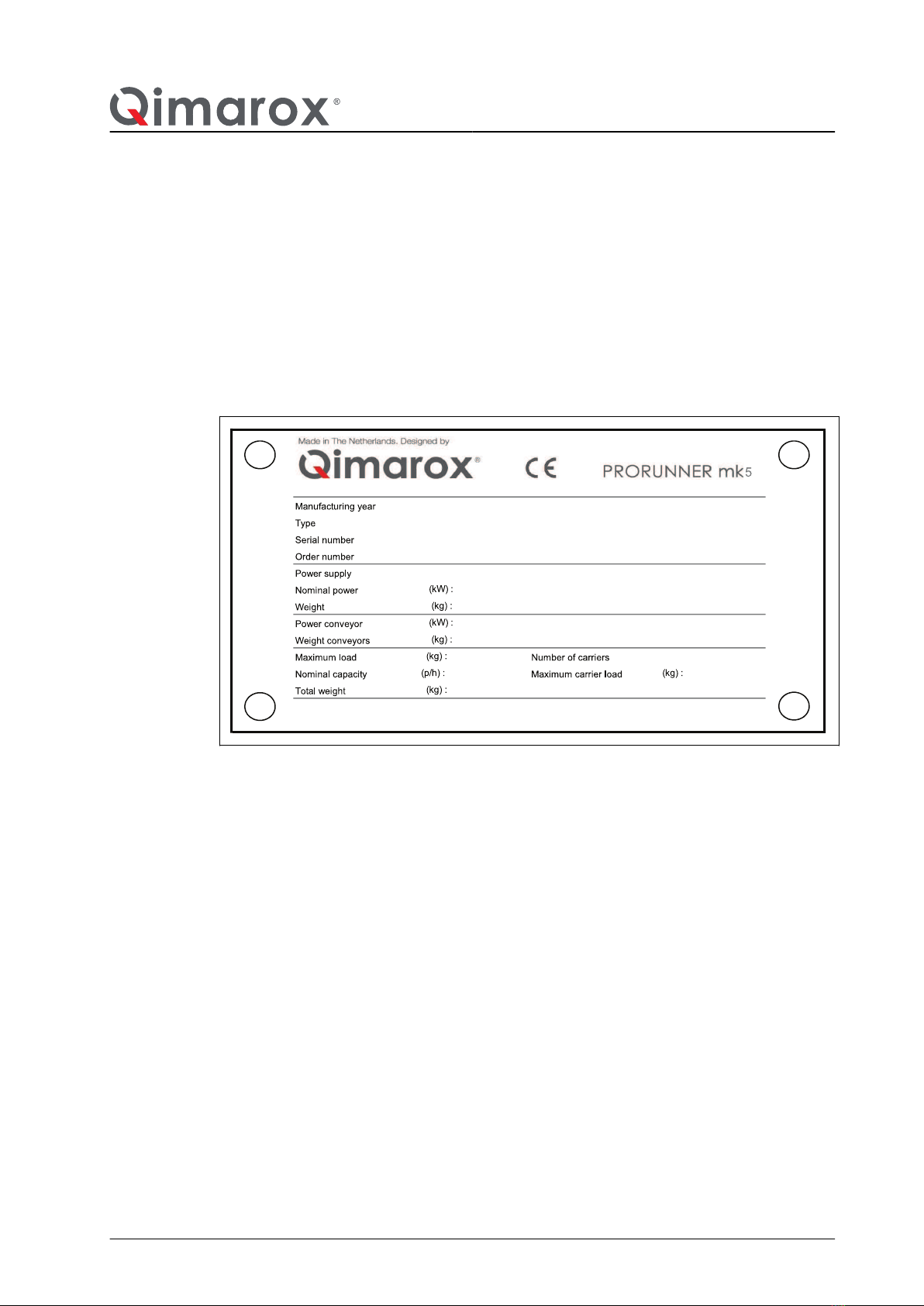
2.1 Machine identification...............................................................................................................9
2.2 Machine layout drawing and specifications............................................................................ 10
2.3 Warranty................................................................................................................................. 11
2.4 Liability....................................................................................................................................11
2.5 CE Declaration of Conformity.................................................................................................12
2.6 Patent..................................................................................................................................... 12
3 Safety
3.1 Intended use of the machine.................................................................................................. 13
3.2 User types and qualifications................................................................................................. 13
3.3 Safety instructions.................................................................................................................. 13
3.4 Safety provisions.................................................................................................................... 15
3.5 Sound level.............................................................................................................................17
3.6 Personal safety.......................................................................................................................17
3.7 Potential risks......................................................................................................................... 19
3.8 Machine end of life and environment disposal....................................................................... 19
4 Description
4.1 General overview................................................................................................................... 21
4.2 Working principles.................................................................................................................. 21
4.3 Sensors.................................................................................................................................. 23
4.4 Motor...................................................................................................................................... 26
4.5 Control system....................................................................................................................... 27
4.6 Guiding of the carriers............................................................................................................ 28
4.7 Machine in a system...............................................................................................................28
4.8 Specifications......................................................................................................................... 31
Table of Contents
UM-Prorunner mk5-2.0-EN 3

5 Installation
5.1 General...................................................................................................................................33
5.2 Delivery.................................................................................................................................. 33
5.3 Possible installations.............................................................................................................. 34
5.4 Unpacking.............................................................................................................................. 35
5.5 Location..................................................................................................................................35
5.6 On-site transport.....................................................................................................................36
5.7 Preparations for installation by Qimarox (optional)................................................................ 38
5.8 Installing the machine.............................................................................................................38
5.9 Installing conveyors................................................................................................................46
6 Maintenance
6.1 General...................................................................................................................................48
6.2 Specific safety regulations......................................................................................................48
6.3 Preventive maintenance.........................................................................................................49
6.4 Cleaning................................................................................................................................. 53
6.5 Lubrication..............................................................................................................................54
6.6 Chain maintenance................................................................................................................ 54
6.7 Bottom sprocket plain bearing rejection dimension................................................................57
6.8 Plain bearing (between trolley and leveller) rejection dimension........................................... 57
6.9 Replace parts......................................................................................................................... 57
7 Troubleshooting
8 CE declaration of conformity
9 Exploded views
9.1 General...................................................................................................................................85
9.2 Machine overview...................................................................................................................86
9.3 Top section............................................................................................................................. 88
9.4 Middle section........................................................................................................................ 92
9.5 Bottom section........................................................................................................................94
9.6 Supports................................................................................................................................. 96
9.7 Drive (option)........................................................................................................................102
9.8 Carrier...................................................................................................................................110
9.9 Lowering adapter..................................................................................................................118
9.10 Labels...................................................................................................................................120
4 UM-Prorunner mk5-2.0-EN

10 Electrical circuit diagrams
10.1 Standard electric drawings................................................................................................... 122
10.2 Drives................................................................................................................................... 122
Table of Contents
UM-Prorunner mk5-2.0-EN 5

1 About this manual
1.1 Introduction
This manual gives information about the Prorunner mk5. From here on, the Prorunner
mk5 is referred to as the 'machine'.
The function of the machine is vertical movement of products within a transport system.
This manual is intended for:
• Retailers/Original Equipment Manufacturers (OEM) project engineers and mechanics.
• Operators, installation and maintenance engineers and other users.
As soon as possible after purchase of the machine, carefully read this manual.
Before you operate the machine, you must read this manual.Make sure that you are
familiar with the content of the manual and the machine.
System integrators/OEMs
This manual explains machine configurations that can be used to set up the machine. It
also provides instructions on how to add or change the machine’s technical components.
Users
The machine may be supplied fully assembled. If so, some chapters in this manual will
not be applicable.
To integrate the machine within a transport system, refer to the documentation provided
by the OEM of the transport system.
1.2 Product documentation
Document Reference
Machine manual* UM Prorunner mk5 v2.0 EN
Machine assembly instructions* AI-Prorunner mk5 v2.0 EN
Electrical components Refer to the manufacturer
Electrical drawings* Refer to section 10
Specifications document** Refer to section 2.2
* Generic information for each machine, apart from exceptions outlined in the Machine layout
drawing. Download from https://www.qimarox.com.
** Machine specific information.
About this manual
6 UM-Prorunner mk5-2.0-EN

1.3 Source language
This manual was originally written in the English language.
1.4 Drawings
Drawings and illustrations used are examples and may differ from the actual situation in
details.
1.5 Symbols used in the manual
The following symbols are used in this manual:
Warning
Risk of serious injury to the user if the instructions are not accurately
followed.
Caution
Risk of damage to the machine if the instructions are not accurately followed.
Note
To provide additional information to the user about a task or issue.
1.6 Terminology list
For the machine, the following common terms are used.
Term Definition
Machine Machine name
Product Products transported by the machine.
Fork The component which carries the product.
Feeding conveyor The conveyor that delivers products to the machine. The
feeding conveyor is not part of the machine.
Discharge conveyor The conveyor that discharges products from the machine. The
discharge conveyor is not part of the machine.
Fenced area Area around the machine that unauthorized personnel cannot
enter for safety reasons.
About this manual
UM-Prorunner mk5-2.0-EN 7

Term Definition
Infeed conveyor The feeding conveyor puts products on the infeed conveyor.
The infeed conveyor is not described in this manual. As a
complete system, the infeed conveyor is part of the machine.
Outfeed conveyor The outfeed conveyor puts products on the discharge
conveyor.
The outfeed conveyor is not described in this manual. As a
complete system, the outfeed conveyor is part of the machine.
1.7 Further support and information
Qimarox can supply additional expertise and support services, for:
• Training.
• Global support.
• Service contracts.
For more information, please contact Qimarox.
About this manual
8 UM-Prorunner mk5-2.0-EN

2 General
2.1 Machine identification
The machine identification is given on the type plate. For the location, refer to section
9.10.
Refer to the Specifications document of the machine for an explanation of the serial
number, for the specifications and for the applicable products.
:
:
:
:
:
:
2.1.1 Machine overview
The figure shows the main components.
General
UM-Prorunner mk5-2.0-EN 9

A. Drive
B. Fork, on trolley and leveller
C. Chain
D. Frame
2.2 Machine layout drawing and specifications
After a machine order is placed, a Machine layout drawing and Specifications document
is handed over for approval. After approval, the Specifications document is used as a
reference for this manual.
The complete technical documentation of
the machine consists of:
• Machine layout drawing (see
sample).
• Specifications document (see
sample).
• Electrical drawings.
• Functional software description of the
software function block.
A
C
D
B
General
10 UM-Prorunner mk5-2.0-EN

This Machine layout drawing and the
Specifications document include:
• The machine serial number.
• Product dimensions and mass.
• Machine dimensions.
• Machine configuration.
• Motor specifications.
• The number of forks.
• Electrical components
The machine can only be used according
to the specifications in this manual, the
Machine layout drawing and the
Specifications document.
If you want to use the machine outside the recommended specifications, you must
contact Qimarox to check if this is possible. Inappropriate and/or modified use of the
machine can result in dangerous safety issues and/or damage. You must obtain written
confirmation from Qimarox before using the machine in a modified or unspecified manner.
Qimarox cannot be held liable for any accidents and/or damages that may occur through
inappropriate unauthorised use of the machine.
2.3 Warranty
The scope and duration of the warranty is agreed upon when an order is placed for the
machine. The warranty only applies if the machine is used according to the specifications
and if the user and maintenance instructions are observed. The warranty does not cover
wear of the parts.
The machine warranty is null and void in cases of:
• Unskilled usage.
• Inadequate maintenance.
• Unskilled maintenance.
• Modifications made to the machine without prior written permission from Qimarox.
2.4 Liability
Qimarox believes to the best of its knowledge that the information in this user manual is
accurate. In the event that technical or typographical errors exist, Qimarox reserves the
right to make changes to subsequent editions of this user manual without prior notice to
holders of this edition. The reader should consult Qimarox if errors are suspected. In no
event shall Qimarox be liable for any damages arising out of or related to this user
manual or the information contained in it. Except as specified herein, Qimarox makes no
v4.0 1/9
mk5
/
-
N/A
/€
Requested capacity 400 Products / hour
Default: Steel
Default: Steel
Default: Powder coated
Column Default: RAL 9007
Conveyors Default: RAL 7037
Side covers Default: RAL 3020
Back covers Default: RAL 3020
Front cover alupanel Glossy Default: Silver 9006
Default: Steel
Default: RAL 9005
50 Hz
No
1 year Default: 1 year
Default: English UK
IEC
Prorunner mk5
Quotation / order number
Serial number
18XXXXX
mk5 18XXXXX rev -
MATERIAL & SURFACE TREATMENT
Discount / Currency
QS180XXX
Line number / Customer PO
Date
Customer
Colour
N/A
APPLICATION
Revision
Material
N/A
N/A
Position
Safety switch
Silver 9006
SAFETY FENCING
RAL 3020
RAL 3020
Material of levelling feet
Steel
Material
English UK
SPECIAL CUSTOMER REQUESTS
WARRANTY & DOCUMENTATION
User manual language
Warranty
Motor voltage
Brake voltage
Certification
Food grade oil in gearmotors
230/400V
230V AC (220-242V)
N/A
Powder coated
GENERAL GEARMOTOR PROPERTIES
Line frequency
Surface treatment
Steel
RAL 9007
RAL 7037
www.qimarox.com
General
UM-Prorunner mk5-2.0-EN 11

warranties, express or implied, and expressly disclaims any warranty of non-infringement,
merchantability or fitness for a particular purpose. Customer's right to recover damages
caused by fault or negligence on the part of Qimarox shall be limited to the amount paid
to Qimarox by the customer. Qimarox shall not be liable for damages resulting from loss
of data, profits, use of products, or incidental or consequential damages, even if advised
of the possibility thereof. This limitation of liability of Qimarox will apply regardless of the
form of action, whether in contract or tort, including negligence. Any action against
Qimarox must be brought without one (1) year after that cause of action accrues.
Qimarox is not liable for damages, unsafe conditions, defects, malfunctions, or service
failures caused by the following:
• Owner’s or user’s failure to follow Qimarox's installation, operation and maintenance
instructions, including but not limited to neglecting warnings or regulations as shown
on the machine or in this manual.
• Usage of the machine for other applications, or under other circumstances than
indicated in this user manual. This includes abuse, misuse or negligent acts.
• Modifications of any kind to the machine. This includes the replacement of parts with
parts that are not specified in this manual.
• Insufficient or improper maintenance.
2.5 CE Declaration of Conformity
For the CE Declaration of Conformity, refer to the Specifications document.
2.6 Patent
Patent protection applies to parts of the machine. Consequently, other parties are not
permitted to build this machine in this form, unless Qimarox B.V. has explicitly given
permission for this. For more information, refer to mk5patents.qimarox.com.
General
12 UM-Prorunner mk5-2.0-EN

3 Safety
3.1 Intended use of the machine
The machine is exclusively intended for the vertical transportation of goods, as described
in this manual. For a detailed description of the specifications of use, refer to section 4.
The machine is always set up within a larger transport system in which products are
automatically loaded on and off the machine.
Warning
Any other use of the machine is strictly forbidden.
3.2 User types and qualifications
The following user types are referred to in this manual:
• The operator.
• The electrical installer.
• The maintenance engineer.
• The mechanical installer.
The maintenance engineer must be familiar with the full content of this manual.
Before any person sets up, electrically installs or maintains the machine, permission to
carry out these tasks must be obtained from Qimarox. Qimarox determines if the person
is qualified for carrying out the given task. The machine should only be operated by
qualified personnel.
An electrical installer is only qualified if a person has attended appropriate training and/or
attained appropriate industry standard recognized qualifications. Qimarox can provide
training if required.
Qimarox can also give advice about actions and tasks to be carried out on the machine.
3.3 Safety instructions
3.3.1 General
• Comply with the safety regulations given in this manual. Deviation from these
regulations can lead to unacceptable risks.
• Never close doors (if present) in the fenced area of the machine, when personnel are
inside this area.
Safety
UM-Prorunner mk5-2.0-EN 13

• Switch off the machine and secure the main power supply switch in the off position
with a padlock to prevent the machine from being switched on while personnel work
in the fenced area.
• Comply with all relevant local legislation and regulations.
3.3.2 Set up
• Connect the machine in accordance with the local laws and regulations concerning
safety and health.
• Before putting the machine into use, check if the machine has been set up in
accordance with the instructions in this manual and with the layout drawing.
• Make sure that the transport system complies with all relevant health and safety
directives and regulations.
3.3.3 Start the machine
• Do not switch the main power supply on when persons are in contact with the
machine.
• Do not start the machine when persons are in contact with the machine.
• Do not start the machine when persons are present in the fenced area of the
machine.
• Before the machine is put into operation, all machine parts must comply with all
relevant health and safety directives and regulations.
3.3.4 During machine operation
• Keep your hands and feet away from the fenced area.
• Make sure you do not wear loose clothing and secure long or loose hair.
• Make sure that no persons or objects are within the range of any moving parts of the
machine.
• Make sure that users know and observe all safety rules with regard to the machine
and the environment in which it operates.
3.3.5 Maintenance and repair
• Turn off the power of the machine using the main power supply switch before starting
any maintenance or repair tasks. Secure the main power supply switch in the off
position with a padlock.
• Replace damaged or defective parts before putting the machine back into operation.
• Changes and modifications that may affect the safety of the machine can only be
carried out when these changes and modifications comply with the relevant
regulations, legislation, directives and recognized industry standards.
Safety
14 UM-Prorunner mk5-2.0-EN

• If changes and modifications are outside the scope of specifications given by Qimarox
in this manual and Qimarox has not granted permission changes and modifications,
then the changes and modifications will entirely be the responsibility of those persons
responsible for carrying out the changes and modifications.
• Electrical installation tasks must only be carried out by qualified personnel.
3.4 Safety provisions
3.4.1 Safety equipment
• Do not disassemble, bypass or disable any safety equipment on the machine.
• Do not start the machine if even a single item of the machine safety equipment is
defective.
• Immediately take the machine out of operation if a single item of the machine safety
equipment is defective.
• Always replace all safety equipment that have been removed from the machine when
all maintenance tasks are complete.
The machine should have the following safety equipment:
• Covers with labels.
• Interlock switches that trigger the safety system.
• Emergency stop buttons.
Note
Replace inreadable or damaged labels on the machine.
For safety reasons, Qimarox requires a fenced area around the machine. Any access
doors must be secured with (interlock) door switches. The (interlock) door switches must
be included in the emergency stop and safety circuit. For information about how to set up
the fenced area, refer to section 3.4.2 .
In case of non-compliance with the required safety measures, the CE Declaration of
Conformity will become null and void.
3.4.2 Safety fences
The fenced area must comply with EN ISO 13857 and EN 619 standards.
Make sure that the fence, the fenced area and safety control system comply with local
safety laws and safety rules.
The infeed and outfeed openings of the machine must prevent persons from entering the
danger zone when the machine may cause a danger to a person in that area. Every
infeed and outfeed opening must be fitted with a safety device (door with a safety switch,
light curtain, etc.) that is embedded in the safety control system, to control the access. All
Safety
UM-Prorunner mk5-2.0-EN 15

machines in the fenced off area must stop if the safety control system is triggered due to
unsafe access.
If Qimarox supplies the safety fencing, a layout drawing of the safety fencing will be
provided. Refer to the figures as examples.
Warning
If the machine moves the products through a floor to another level, apply
safety measures to all levels.
3.4.3 Safety controls
The provisions must be designed according to a so-called Performance Level (PL)
corresponding with the current standard for safety functions of a machine or a machine
control in compliance with EN ISO 13849-1:2016. To the machine a PL_d applies, in
which 'd' indicates that the risk must be substantially reduced.
Safety
16 UM-Prorunner mk5-2.0-EN

Emergency stop circuit
The machine must have an emergency stop circuit. When one of the emergency stop
buttons is pressed, the main power and the control current of the machine are switched
off immediately.
Set the motor protection relay
Motor protection devices must be set to the nominal motor current. A relay set too low
prevents optimum use of the motor. A relay set too high does not guarantee full thermal
protection.
Thermistor protection (TF contact)
For motors that are frequently started and stopped, intermittently operated, use a high
switching frequency or power controller, it is essential to use a motor protection relay and
thermistor protection. This is to avoid prematurely switching the motor protection relay or
overheating of the motor winding in these operational conditions.
Check of the transport time slot
The software should monitor the position of the products in the machine during infeed,
internal transport and outfeed. When the related time slots are exceeded, the machine
must immediately stop to avoid damage.
3.5 Sound level
The sound level of the PRORUNNER Mk5 is 80.9 dB(A). To measure and calculate the
sound level, refer to the standards ISO 3740 and ISO 3744.
If necessary, ask Qimarox for a full report.
3.6 Personal safety
For your own safety use personal protective equipment.
Always wear proper personal protective equipment when working with, on or near the
machine.
The following table gives an overview of the required personal protective equipment.
Safety
UM-Prorunner mk5-2.0-EN 17

Safety sign Protective device
(example)
Description When required
Safety helmet During maintenance
Protective goggles During maintenance,
cleaning
Hearing protection During production
Protective gloves
(no leather, but rubber
or silicone!).
During cleaning
Protective shoes During cleaning and
with slippery floors
Safety
18 UM-Prorunner mk5-2.0-EN

Safety sign Protective device
(example)
Description When required
Protective clothing During cleaning
Safety harness/belt
Take off your personal protective equipment during a work break to prevent possible
residue from getting onto canteen tables and in your food.
3.7 Potential risks
The machine is intended to be integrated into a transport system. Qimarox has attempted
to protect against as many hazards as possible.
The following potential risks should be addressed before machine and assembled parts
are put into operation:
• Risk of injury caused by falling products.
• Risk of injury as a result of moving fork and conveyor.
• Hazards occurring at places where the machine connects to other parts of the
production line, such as supply and discharge conveyors.
The interior of the machine can be accessed through the front of the machine. Protection
is required at the supply, discharge, infeed and outfeed conveyors.
Protective measures must be applied on each floor level.
3.8 Machine end of life and environment disposal
Proper use and maintenance of the machine will not involve any environmental risks.
After the machine is no longer useable, the machine should be dismantled and disposed
of in an environmentally responsible manner.
Warning
Obey all relevant legislation, regulations, instructions and precautions
with regards to health and safety when dismantling the machine.
Safety
UM-Prorunner mk5-2.0-EN 19

Warning
Obey all relevant legislation, regulations, instructions and precautions
with regard to the disposal of products in the environment.
Safety
20 UM-Prorunner mk5-2.0-EN
Other manuals for PRORUNNER Mk5
3
Table of contents
Other Qimarox Accessories manuals