MAS Genio INM Series User manual

Revision No: 03 July/2018
In-Line Centrifugal Pumps with Frequency Inverter
GENiO INM SERIES
OPERATING MANUAL

EC DECLARATION OF CONFORMITY
AT UYGUNLUK BEYANI
Manufacturer / İmalatçı
: MAS DAF MAKİNA SANAYİ A.Ş.
Address / Adres
: Aydınlı Mah. Birlik OSB. 1.No’lu Cadde No:17 Tuzla - İSTANBUL / TÜRKİYE
Name and address of the person authorised to
compile the technical file
Teknik Dosyayı Derleyen Yetkili Kişi ve Adresi
Vahdettin YIRTMAÇ
Aydınlı Mah. Birlik OSB. 1.No’lu Cadde No:17
Tuzla - İSTANBUL / TÜRKİYE
The undersigned Company certifies under its sole responsibility that the item of equipment specified below satisfies the
requirements of the mainly Machinery Directive 2006/42/EC which is apply to it.
The item of equipment identified below has been subject to internal manufacturing checks with monitoring of the final assessment
by MAS DAF MAKİNA SANAYİ A.Ş.
Aşağıda tanımlanmış olan ürünler için Makine Emniyeti yönetmeliği 2006 / 42 / AT’ nin uygulanabilen gerekliliklerinin yerine
getirildiğini ve sorumluluğun alınmış olunduğunu beyan ederiz.
Aşağıda tanımlanan ürünler içüretim kontrollerine bağlı olarak MAS DAF MAKİNA SANAYİ A.Ş. tarafından kontrol
edilmiştir.
Equipment / Ürün
: In-Line Centrifugal Pumps / In-Line Santrifüj Pompalar
Seri / Model-Tip
: INM / INL Series - INM / INL Serisi
For pumps supplied with drivers/ Elektrikli Pompa Üniteleri Related Directives / Yönetmelikler
2006/42/EC Machinery Directive / 2006/42/AT Makine Emniyeti Yönetmeliği
2014/35/EU Low Voltage Directive / 2014/35/AB Alçak Gerilim Yönetmeliği
2014/30/EU Electromagnetic Compatibility Directive / 2014/30/AB Elektromanyetik Uyumluluk Yönetmeliği
EUP 2009/ 125 /EC Electric Used Products Directive/ Elektrik Kullanan Ekipmanlar Direktifi (EUP)
94/9/EC Equipment For Explosive Atmospheres / Patlayıcı Ortamlardaki Ekipman Yönetmeliği
2009/125/EC European Ecodesign Directive, Regulation No: 547/2012 Ecodesign Requirements for Water Pumps / Avrupa
Ekotasarım Direktifi, (SGM-2015/44) 547/2012 No’lu Su Pompalarında Ekotasarım Regülasyonu
Regulations applied acc. to harmonize standards / Uygulanan Uyumlaştırılmış Standartlar
TS EN ISO 12100:2010, TS EN 809+A1, TS EN 60204-1:2011.
We hereby declare that this equipment is intended to be incorporated into, or assembled with other machinery to constitute relevant
machinery to comply with essential health and safety requirements of Directive The machinery covered by this declaration must
not be put into service until the relevant machinery into which it is to be incorporated has been declared in conformity with
provisions of the directive.
Ekipman, uygun bir makina oluşturmak amacıyla diğer ekipmanlar ile birleştirilirken ya da monte edilirken gerekli sağlık ve
güvenlik yönetmeliklerine uyulması gerekmektedir.
Bu bildiri kapsamında yönetmelikte belirtilen bütün hükümler yerine getirilmeden makinanın devreye alınmaması gerekmektedir.
Place and date of issue / Yer ve Tarih
: İstanbul, 02.06.2014
Name and position of authorized person
Yetkili Kişinin Adı ve Görevi
: Vahdettin YIRTMAÇ
General Manager / Genel Müdür
Signature of authorized person
Yetkili Kişinin İmzası
:

Mas Grup
1
TABLE OF CONTENTS Page No
Introduction 1
1.Important Safety Precautions 1
2.General 1
3.Safe Operating Conditions 2
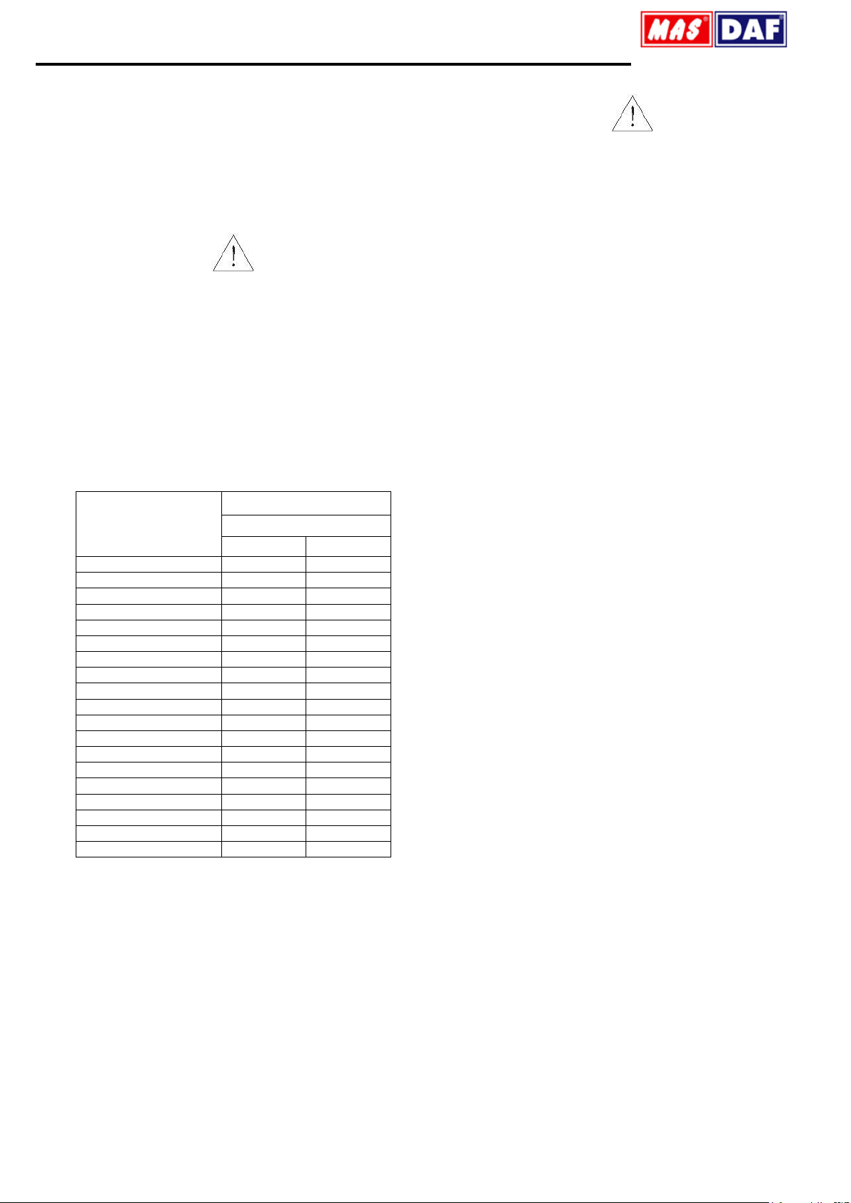
4.Technical Information 3
5.Transport and Storage 3
6.Assembly/Installation 4
6.1.Location of Installation 4
6.2.Piping 4
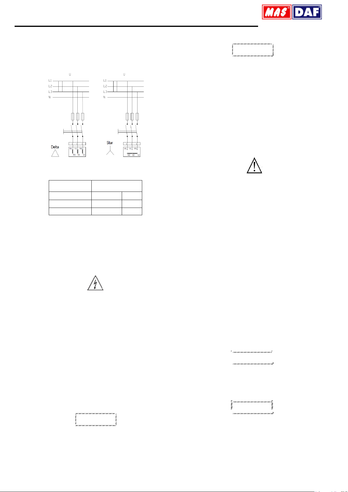
6.3.Motor Connection 4
7.Commissioning, Start up and Operating 5
7.1.Preparations Before Start up 5
7.2.Checking The Direction of Rotation 5
7.3.Start up Procedure 5
7.4.Shut Down Procedure 5
8.Maintenance 6
8.1.The Checks During the Operation 6
8.2.Service 6
8.3.Spare Parts 6
9.Noise Level and Vibration 7
10. Disassembly, Repair and Reassembly 7
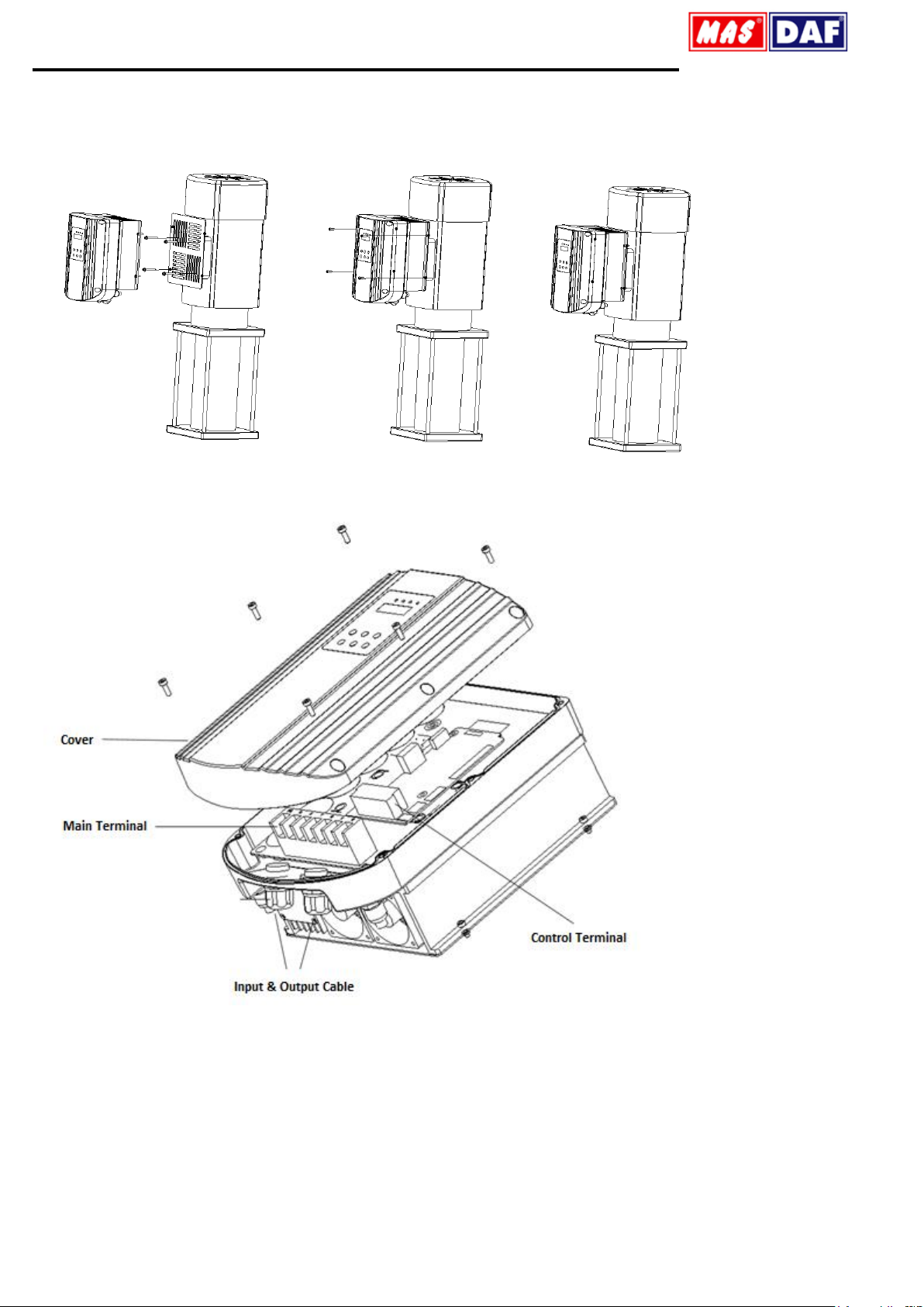
11. Information About Frequency Inverter 8
12. Possible Failures, Causes, Solutions 14
13. Pump Dimensions Table 15
14. Tightening Torques 22
15. Forces And Moments at The Pump Flanges 23
16. Sample Plumbing 24
17. INM/INL Sectional Drawing and Part List 25
18. INM Drawing for Dismantling 28
19. INM/INL Series MEI Value Tables 30
20. Figure List 31
21. Table List 31
INTRODUCTION
This manual contains instructions for the installation, operation and
maintenance of the INM/INL type non-self priming in-line centrifugal
pumps of MAS DAF MAKINA SANAYI A.Ş.
Please read carefully this manual and apply all the instructions to
operate pumps without problems. Pumps shall be used for their
intended duties. In this manual, there are information on operating
conditions, installation, starting-up, settings and main controls of
pumps.
These operating and maintenance instructions contain MAS DAF
MAKINA SANAYI A.Ş.`s suggestions. The special operating and
maintenance information of the plumbing that a pump is fitted to is not
considered in these instructions. This information must be given by the
plumbing constructors only.
Please refer to instructions of plumbing constructors.
Please pay attention to the warnings in this manual and ensure that it is
read before the installation-start up process. MAS DAF MAKINA
SANAYI A.Ş. is not responsible for the accidents resulting from
negligence.
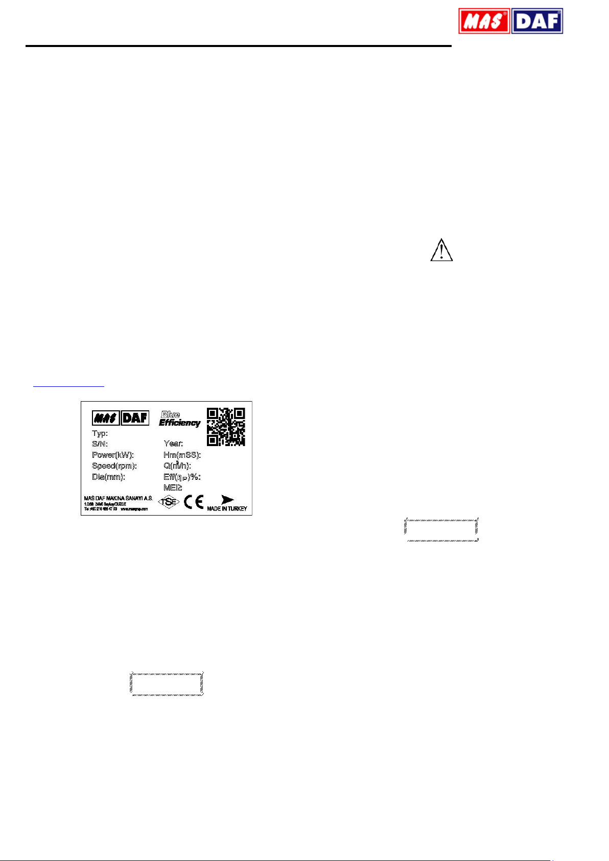
If you cannot find an answer to your questions in this manual, it is
suggested that you contact MAS DAF MAKINA SANAYI A.Ş. Please
inform us about the rated value and especially the serial number of the
pump when you get in contact for help.
The safety instructions in this manual cover the current national
accident protection regulations. Beside all of these, an operation, work
and safety measure imposed by the costumer has to be applied.
The Signs Used in This Operation Manual
Read the instructions carefully in this operating manual
and keep it for your future reference.
Warning sign against the electrical risks
Sign for the operator’s safety.
1. IMPORTANT SAFETY PRECAUTIONS
In order to minimize the accidents during the mounting and putting into
service of the pump, the following rules have to be applied:
1. Do not work without taking safety measures relevant to equipment.
Cable, mask and safety band must be used when necessary.
2. Be sure there is adequate amount of oxygen and there is no toxic
gaseous around
3. Before using welding or any electrical equipment make sure that
there is no risk of explosion.
4. Check the cleanliness of the area to take care of your help. (Dust,
smoke, etc.)
5. Do keep in mind that there is a risk of having accidents related to
electricity
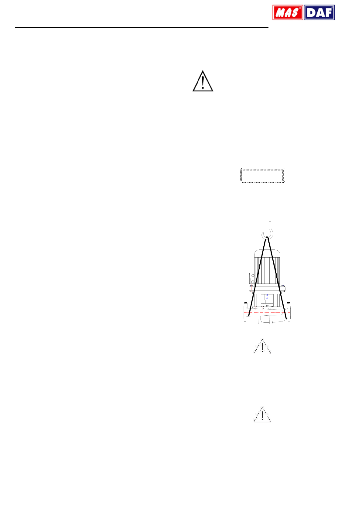
6. Do not lift the pump before you check the transport equipment.
7. Be sure you have a by-pass line
8. Use helmet, eye glasses and protective shoes for your safety
9. Place a protective barrier around the pump within the necessary
safety area
10. Dust, liquids and gaseous that may cause overheating, short circuit,
corrosion and fire must be kept away from the pump unit.
11. By checking the noise level of the pump unit, necessary measures to
avoid noisy operation of the pump that can have harmful effects on
the personnel and environment.
12. Be careful about the direction of transport and storage.
13. Cover appropriately the moving parts to avoid possible injury of the
personnel. Mount the coupling guard and belting before starting-up
the pump
14. All the electrical and electronic applications must be performed by
authorized person conforming EN60204-1 and /or domestic
instructions.
15. Protect the electrical equipment and motor against overloading
16. If flammable and explosive liquids are pumped, ground connection of
electricity should be carried out properly
17. Do not expose the pump unit to sudden temperature variations
18. All personnel who work with the waste water system need to be
vaccinated in case of contagious diseases.
19. If the pump contains hazardous liquids, one must use protective
helmet against the risk of splatter. One also must accumulate the
liquid in a proper container against any risk of leakage.
All Other Health and Safety Rules, Laws and
Regulations Must Be Applied
2. GENERAL
2.1.Definition of Pump and Usage Areas
INM/INL series pumps are non-self priming in-line centrifugal pumps.
They are used in
•Water networks and pressurization facilities
•Irrigation, sprinkling and drainage systems
•Filling-Draining of tanks and reservoirs
•Hot and cold water circulation in heating and cooling systems
•Condense water pumping
•Water circulations in pools
•Health and purification facilities
•Industrial and social facilities
•Fresh and sea water pumping in ships
They shall be used to pressurize liquids (up to 90°C) which are clean or
mildly impure, non abrasive, and not containing large solid particles or
fiber.
CAUTION
Please contact MAS DAF MAKINA SANAYI A.Ş. for liquids that have
different chemical and physical specifications.
INM/INL pumps comply with DIN 24255 standards within nominal
capacity range.
Sign for protecting against explosion.

Mas Grup
2
Technical specifications of INM/INL type pumps
Suction Flange: DN 40-DN 250
Discharge Flange: DN 40-DN 250
Operating Pressure: 10 bar.
Operating Temperature: -25 –120°C
Capacity: 2-800 m3/h
Hm: 2-100 m.
Speed: 900-3600 RPM
Product Information as per Regulation No. 547/2012 (for Water Pumps
with a Maximum Shaft Power of 150 kW) Implementing "Ecodesign"
Directive 2009/125/EC
Minimum Efficiency Index for MAS INM/INL Pump Series is shown on the
pump label.
MEI values of MAS INM/INL Pump Series are shown on the pump
characteristic curves.
Minimum Efficiency Index for MAS INM/INL Pump Series; Minimum 0.4.
(MEI≥0,4)
Efficiency values of the pump characteristic curves, which are cut
diameter, are expressed in %.
INM/INL Series water pumps, the pump efficiency can be achieved more
than fix speed in case of variable speed control.
More information about the Ecodesign can be reached at
www.europump.org
Figure 1: Pump Label
2.2.Performance Inforation
Actual performance of the pump can be obtained from the order page
and/or from the test report. This information is given on the pump label.
The performance curves given in the catalog are valid for water whose
density and viscosity are ρ=1 kg/dm3and ν=1 cst. respectively. For
those liquids whose densities and viscosities are different from those of
water, please consult with MAS DAF MAKINA SANAYI A.Ş. since the
performance curves vary with density and viscosity
CAUTION
Do not operate the pump with a motor that has a different power
except for the given catalog and label values.
The pump is not to be operated at off-design point given in the order and
supplied from the firm.
It is necessary to ensure that the instructions are obeyed for the safe
running of the pump.
2.3.Warranty Conditions
The entire products in our selling program are warranted by MAS DAF
MAKINA SANAYİ A.Ş.
The warranty conditions will only be valid when all the instructions about
installation and start-up operations of the pump unit are taken into
account.
2.4.Test
All Pumps are dispatched for sale when all the performance and pressure
tests are completed. Proper assurance of material and fault-free
operation of pumps whose performance tests are made is under the
warrantyof MAS DAF MAKINA SANAYI A.Ş.
2.5.Pressure Limit
Pressure at the discharge flange must not exceed 16 Bar. A special order
is necessary for applications with higher pressures.
3. SAFE OPERATING CONDITIONS
This manual contains main safety instructions for the installation,
operation and maintenance. It must be read by the personnel who are
responsible for installation and operation. This manual should always be
kept near the installation location. It is important to comply with safety
precautions stated in page 1 along with the general safety instructions as
well as preventive measures repeated in other sections of this manual.
3.1.Training of Personnel
Installation, operation and maintenance personnel must have necessary
knowledge in order to accomplish the given job. The responsibility,
adequacies and controlling duties of such personnel must be determined
by the costumer. It has to be certain that these personnel comprehend
totally the content of the operating manual.
If the personnel do not have enough knowledge, required training must
be given by the costumer. If training support is needed by the costumer,
it will be provided by the manufacturer/seller.
CAUTION
Untrained personnel and unwillingness to comply with safety instructions
may be risky for both machine and environment. MAS DAF MAKINA
SANAYI A.Ş. is not responsible for this kind of damages.
3.2.Hazardous Conditions That May Occur When One does not
Comply With the Safety Instructions
Incompliance with safety regulations may put the personnel, the
environment and the machine in danger and thus may cause damages.
Incompliance with safety regulations may give rise to situations listed
below.
Important operational functions of the factory may stop.
Maintenance may get difficult.
One may get injured by electrical, mechanical or chemical hazards.
3.3.Safety Measures for Operator
Dangerous, hot or cold components in the pump area must be covered so
that one cannot touch them.
Moving components of the pump (such as coupling) must be covered so
that one cannot touch them. Those covers must not be dismounted while
the pump is running. Dangers that results from electrical connections
must be removed. To get more information about this subject, you can
refer to domestic electrical instructions.

Mas Grup
3
3.4.Safety Measures for Maintenance and Installation
The costumer must assure that all maintenance, check and installment
tasks are performed by qualified personnel. Repair work must only be
performed while the machine is not running.
The pump and its auxiliary system must be cleaned thoroughly if it
contains hazardous liquids. At the end of the repair work, all safety and
protective equipment must be re-installed.
3.5.Spare Parts Replacement
Replacement of spare parts and all modifications must be done after
contacting with the manufacturer. Spare parts and accessories certified
by the manufacturer are important for the safe operation of the system.
Notice: MAS DAF MAKINA SANAYI A.Ş. is not responsible from the
usage of improper spare parts.
4. TECHNICAL INFORMATION
4.1.Design
Single stage, non-self priming in-line centrifugal pumps are furnished with
standard pumps and mechanical sealings.
4.1.1.Locations of Flange –Flanges
Discharge Flanges : DIN 2533-PN 16
Suction Flanges : DIN 2533-PN 16
4.1.2.Connection of Pump and Motor
Motor is close coupled to the pump with a rigid coupling using and an
adapter and flange. In this way, the shafts of the motor and pump
constitute a complete unit.
4.1.3.Impeller
The closed radial type impeller of the pump is balanced dynamically in
an electronic balance machine. The thrust (axial force) is balanced with
the back wear ring and balance holes.
4.1.4.Shaft
The shaft, impeller and other parts of the pump is designed to be
dismountable without moving (dislodge) the suction and discharge pipes
and volute of the pump. In this way, the installation and maintenance
operations can be performed very easily.
4.1.5.Bearing and Lubrication
Rolling bearings are not used in INM type pumps. Motor bearing is
enough for countervailing all axial and radial forces.
4.1.6.Seals
In standard production, various mechanical seal types (e.g. bellow type,
spring actuated type) are used for sealing.
4.2.Construction of Pump Group
4.2.1.Drive
TEFC (Totally Enclosed Fan Cooled) 3 phase, squirrel caged, in
accordance to DIN 42673, IM 2001B5 type electrical motor which
complies with DIN IEC and VDE is used to drive the pump in proper
speed and power.
Specifications of electrical motor;
Isolation class: F
Protection class: IP 54-IP 55
Frequency: 50 Hz
Running type: S1
Start up type: Up to 4 kW, 3x380 V (Y)
More than 4 kW, 3x380V (Δ)+(Y/ Δ)
4.2.2.Coupling and Coupling Guard
At INM type pumps, a flexible coupling is used. A coupling guard is given
in accordance with EN 953.
Pump can only be run with a couplingguard in
accordance with EN 953 according to safety
instructions.
If there is no coupling cover, it is provided by the
operator.
5. TRANSPORT AND STORAGE
Suction, discharge and all auxiliary fittings must be closed during
transport and storage. Dead-end covers must be removed while the pump
unit is being installed.
5.1.Transport
Pump and pump group must be carried safely to the installation location
by lifting equipments.
CAUTION
Current general lifting safety instructions must be applied. Please use a
suspension system shown in figure while you are carrying and lifting the
pump unit. The suspension rings may be broken because of the
excessive load and may result in a damage of the pump. Prefer fabric
cable for suspension.
Figure 2: Transport of Pump Group
Incorrect lifting may damage the pump unit and cause injuries.
Damages caused in transport
Check the pump when it is delivered to you. Please let us know of there is
any damage.
5.2.Storage
Please keep the unit clean and dry area during storage.
If the pump is out of use for a long time, please consider the instructions
below.
1.If there is water inside the pump, drain it.
2.Clean the pump casing and impeller by jetting clean water for a short
time.
3.Empty water inside the pump casing, suction line and discharge line.

Mas Grup
4
4.Add small amount of antifreeze inside the pump casing if it is not
possible to empty it completely. Rotate the pump shaft by hand to mix
the antifreeze.
5.Close the suction and discharge exits with gasket
6.Spray an anti-corrosive into the pump casing.
7.Rotate the pump shaft by hand once in every month, in order to protect
it from freezing and to lubricate the bearings.
6. ASSEMBLY / INSTALLATION
In our standard production, the pump and the motor have been installed
in a common base plate.
6.1.Location of Installation
Pump shall be installed in a location where the control and the
maintenance of the pump are easily made. The pump room shall be
suitable for operation of lifting systems such as freight elevator, forklift,
etc.
The pump group should be installed in the lowest possible location of the
pumping system in order to achieve the highest suction pressure.
6.1.1.Location of Installation- Local Ambient Temperature
When the local ambient room temperature exceeds +40oC in a pumping
system, suitable ventilation should be provided in order to remove the
heat dissipated to the environment and supply fresh air.
6.2.Piping
6.2.1.General
Do not use the pump as the hinged support for the piping system.
Put enough supports under the piping system in order to carry the
weight of the pipe and fittings.
Avoid piping system loads on pump by installing flexible components
(compensator) to suction and discharge of the pump.
By mounting flexible supporting items, take into consideration the fact
that these items may elongate under the pressure.
Suction pipe shall be in a constantly increasing slope to the pump. Air in
the suction pipe shall be arranged to move into the pump
Discharge piping shall be in a constantly increasing slope to the
reservoir or discharge point, without up and downs which can cause air
pockets in the piping system. At locations where forming of air pockets
is possible, special items like air valve and air cock are mounted to
evacuate the trapped air.
It is important that pipe diameter and fittings are at least as much as the
pump opening diameter or preferable one or two size higher. One
should never use fittings with smaller diameters than the pump exit
diameter. In particular, preferred fittings like foot valve, strainer, filter,
check valves and valves shall have large free passing area, and low
friction loss coefficient.
For piping systems with hot liquids, thermal expansions are to be taken
into account and compensators shall be mounted in accordance with
these expansions. Caution shall be exercised to avoid the loading of
pump in this installation.
6.2.2.Specification of Work in Piping Installation
In installation of pipes, follow the procedures below certainly.
•Install the pump on the concrete base as illustrated in Figure 2.
•Take out the guards (placed by the manufacturer) from suction and
discharge openings of the pump.
•Close the suction and discharge flanges with rubber gaskets. This
precaution is important to avoid the undesired substances (weld crust,
weld slag, sand, stone, wood piece etc.) get into the pump. Do not take
off this gasket until the installation is completed.
•Start the installation of piping from the pump side. Do the necessary
assembling and welding of the parts in a successive order.
•In these operations, do not neglect to put the necessary supports in
their respected locations.
•Following above procedure, complete all piping system at suction side
up to the suction tank (or foot valve if available), at discharge side up to
do discharge collector and discharge pipe.
•When all installation and welding process is done and the heat
dissipated by welding is removed, dismantle all the bolted connections
from the suction tank to discharge pipe. Take out all demountable parts.
•Clean these parts and then paint body coat completely inside and
outside.
•Mount the parts again in their intended places. However, this time start
from the discharge line and move downward to the pump. In this
instance, do not forget to check the flange gaskets. If needed, (for
example deformation during welding) replace them.
•Concerning the connection of the pump flanges to piping, in case of
misalignment of axis and flange holes, do not force the system to
eliminate the misalignment. Forcing the system may cause difficult-to-
correct problems.
•If there is an axial misalignment between the flanges of the pump and
the pipe, due to the welding or any other reasons, cut the pipe from a
suitable location in order to fix the problem. Connect the pipe (pump
side) to the pump. After carrying out the necessary correction, connect
the parts again by welding..
•Dismantle and clean the last welded part. Repaint again and mount on
its place.
•After all these processes are accomplished, remove the rubber gasket
from the suction and discharge openings. Open their holes and mount
them again on their intended place.
6.2.3.Specification of Work after Installation of Piping and Piping
System
Installing Pipes
Suction line (top wiew)
Suction line (bottom wiew)
Suction flange
Suction flange
Figure 3: Piping System
An illustrative piping system is shown in Figure 6. Appropriate
manometers shall be mounted on suction and discharge pipe lines.
Complete the auxiliary pipe connections in piping system if exist (cooling
to bearing housing, and stuffing box (seal), relief pipe, oil pipe etc.)
6.3.Motor Connection
Motor shall be connected by an electrical technician according to the
connection (switch) diagram. Local electricity policies regulations have to
be applied.
•Electrical connections have to be made by authorized electricians.
•In dismantling the pump, make sure the electricity is cut off before
taking the motor cover out.
•Use the appropriate electrical connection to the motor.

Mas Grup
5
6.3.1.Motor Connection Diagram
Motors requiring high moments at start up shall not be connected star-
delta
Frequency controlled motors, require high moment at start up and have to
be cooled properly at low speeds. Provide the necessary cooling for the
motors.
Figure 4: Electric Connection Diagram
Electrical circuit
Motor
U (Volt)
230/400 V
400 V
3 x 230 V
Delta
3 x 400 V
Star
Delta
6.3.2.Motor Protection
•Three phased-motor shall be connected to power supply.
•Wait the motor to cool down when thermic protected motor breaks in
circuit due to the overheating. Make sure the motor does not start
automatically until it cools completely
•In order to protect the motor from overcharging and short circuit use a
thermic or thermic-magnetic relay. Adjust this relay to the nominal
current of the motor.
Electrical equipments, terminals and the components of the control
systems may carry electric current even though they are not
operating. They may cause deadly and serious injuries or
irreparable material damages.
7. COMMISSIONING, START UP AND OPERATING
7.1.Preparations Before Start Up
Check pump seals
Make sure that the pump and the suction pipe is completely filled with
water before the starting. If the pump operates on a positive suction
head, no problem will be encountered. Suction valve is opened and air
drains are un-tightened.
Pumps with foot valve are filled with water by opening the pump filling
tap or, one takes advantage of the water accumulated in the discharge
pipe and by using a small valve the check valve is bypassed and the
pump is filled.
In vacuum pump driven pumps, by operating the vacuum pump one
achieves to fill the pump via increasing the water level in the suction
pipe.
CAUTION
Do not start your pump dry (WITHOUT WATER).
7.2.Checking The Direction of Rotation
CAUTION
•The direction of rotation is indicated on the pump label with an arrow.
Apart from special cases, it is clockwise direction when looking from the
motor end. Observe if the pump is rotating in the expected sense by
starting the motor for a very short instant. If it is turning in the opposite
sense, interchange any of two motor leads.
•If the motor connection is delta, open the discharge valve slowly.
•If the motor connection is star-delta, set the time relay to maximum 5
seconds. Monitor the passage from star to delta by pressing the start
button. As soon as you are assured that the connection is delta, open
the discharge valve slowly. Continue opening the valve until you read
the amperage on the electrical panel
•One should always check the labels which show the direction of
rotation and the direction of fluid flow. If you dismount the
coupling protection to monitor the direction of rotation, do not
restart the engine before remounting the protection.
As a result of getting in touch with rotating and stable parts each
other temperature increase can occur. Never check the direction of
rotation while the pump is dry.
7.3.Start up Procedure
Check if the suction valve is open and the discharge valve is closed.
Start the motor
Wait until the motor reaches sufficient speed. (In Star-delta
connections, wait until the engine passes to delta connection.)
Keeping an eye on the amperage shown on the panel, open the
discharge valve slowly.
In the primary operation, if the discharge pipe is empty, do not open the
valve completely. By keeping an eye on the amperage, open the valve
with care regarding that it should not exceed the value indicated on
pump’s label.
After opening the valve completely, check the pressure from the pump
exit manometer and make sure that this value is the pump operating
pressure value and is indicated on pump’s label.
If the value one reads is less than the pump label value when the valve
is completely open, it means that the height is miscalculated. Increase
the value by narrowing the valve and bring it to pump’s label value.
If the value one reads is greater than the pump label value when the
valve is completely open, it means that the height is calculated less
than what it should be in reality. The device is pumping less than what
is requested. Check the installation and the calculations.
Minimum flow rate: If the pump is working with zero flow rates (closed
valve) from time to time during its operation, the water inside the pump
may endanger the pump by getting warmed up. In such cases, a
minimum flow valve must be connected to the pump exit.
CAUTION
Stop the motor if the pump gets too hot. Wait until it gets cold.
Then start the system up again carefully.
7.4.Shut Down Procedure
CAUTION
During sudden start ups and stops, a pressure reducing valve must be
placed at the exit section of high flow rate pumps whose discharge
pipelines are long, in order to reduce water hammer effect. Water
hammer may explode the pump.
In normal conditions (apart from sudden power shut down, etc), stop the
pump as below:
•Close the discharge valve slowly
•Switch the power off, stop the motor. Notice that the rotor slows down.
•Do not start up the motor at least before 1 to 2 minutes.

Mas Grup
6
•If the pump will be out of use for a long time, close the suction valve
and auxiliary circuits. If the pump is outside and if there exists a danger
of frost, remove all drain taps and empty all the water inside the pump.
(5.2. Storage)
CAUTION
If the pump is outside and if there exists a danger of frost, remove
all drain taps and empty all the water inside the pump.
8. MAINTENANCE
CAUTION
Maintenance operations must be done by authorized personnel with
protective clothing only. The personnel must also beware of high
temperatures and harmful and/or caustic liquids. Make sure that the
personnel read carefully the manual.
•The instructions in Safety Precautions must be executed during
maintenance and repair
•Continuous monitoring and maintenance will increase the engine’s and
pump’ s lives.
The instructions below should be applied.
8.1.The Checks During the Operation
Pump must never be operated without water.
Pump must not be operated for a long time with the discharge valve
closed (zero capacity).
Precautions must be taken against flare up when the component
temperatures are over 60C. “Hot Surface” warnings must be placed
over necessary areas.
All the auxiliary systems must be in use while the pump is operating.
If the pump has mechanical sealing, there is no need for excessive
maintenance. Water leakage from the mechanical sealing indicates the
fact that the sealing is worn out and therefore needs to be replaced.
If the system consists of a substitute pump, keep it ready by operating it
once a week. Check also the auxiliary systems of the substitute pump.
Occuring explosive ambient inside of the pump must be prevent. The air
of the pump and suction line must be drained before commissioning of
the pump. The interior of the pump contacting with pumped liquid
including gasket way and auxiliary systems must be filled with pumped
liquid.
Ensure that delivery pressure is enough.
Exceeded the allowable using limits regarding pressure, temperature,
transportating material and motor speed may cause explosion risk, hot
and poison liquid may leak to external environment.
8.1.1.Component Check
CAUTION
To make possible the visual control, one must be able to reach the pump
from any direction. Especially, to be able to dismount the internal units of
the pump and the engine, sufficient free space must be created around
them for maintenance and repair. Furthermore, one must make sure that
the piping system can easily be dismounted.
8.1.2.Bearing and Lubrication
Rolling bearings are not used in INM/INL type pumps. Motor bearing is
enough for countervailing all axial and radial forces. Motor bearings are
provided with lifelong heat resistant grease.
8.1.3.Mechanical Seal
Mechanical seals are used in INM/INL type pumps. Mechanical Seals are
absolutely leak-proof and needs less maintenance than soft packing.
Mechanical seal;
1.Provides leak proof operation in heavy operating conditions (in
waste water pumps, chemical process and refinery pumps).
2.Easily mountable and needs less maintenance.
3.Does not cause wearing on the shaft
4.Sealing operation does not depend on the quality of shaft
finishing.
8.1.4.Drive
Apply to the operating instructions of the motor manufacturer.
8.1.5.Auxiliary Components
Check regularly the fittings and the gaskets, replace the worn out pieces.
8.2.Service
Our Customer Service Department offers after-sale service. Manager
should employ authorized and trained personnel for
mounting/dismounting procedures. Before these procedures, one must
make sure that pump interior is clean and empty.
This criterion is also valid for the pumps which are sent to our factory or to
our service points.
Maintain the safety of the personnel and the environment in every
field procedure.
8.3.Spare Parts
The spare parts of INM/INL type pumps are guaranteed for 10 years by
MAS DAF MAKINA SANAYI A.Ş.
In your spare parts requests, please indicate the below listed values that
are indicated on your pump’s label.
Pump type and size:
Motor power and speed:
Pump serial number:
Capacity and head:
If you wish to keep spare parts in store, depending on the number of
same type of pumps, for two operation years, the quantities which are
listed in the table below are recommended.
Component Name
The Number of Equivalent Pumps in the
Installation
1-2
3
4
5
6-7
8-9
10+
Shaft (Key included)
(quantity)
1
1
2
2
2
3
%30
Impeller (quantity)
1
1
1
2
2
3
%30
Mechanical Seal
1
2
2
3
3
4
%50
Wear ring
1
1
1
2
2
3
%50
Rigid clamped
coupling (INL)
1
2
2
3
3
4
%50
Table 1: Spare Part List

Mas Grup
7
9. NOISE LEVEL AND VIBRATION
The reasons which increase the noise level are indicated below:
•Touch of coupling halves due to worn rubber sleeves (incorrectly
aligned)
•Noise level increases due to the fact that the pump is not founded
properly (Vibration)
•If the installation does not have compensator noise and vibration
increases.
•Wearing in ball bearing also increases noise level.
Check if there is any noise increasing elements in your installation.
9.1.Expected Noıse Values
Measurement conditions:
The distance between the measure point
and the pump
: 1m
Operation
: Without Cavitation
Motor
: IEC Standard Motor
Tolerance
: ±3 dB
Power of Motor PN [kW]
Sound Pressure Level (dB) *
Pump with Motor
1450 rpm
2900 rpm
< 0,55
63
64
0,75
63
67
1,1
65
67
1,5
66
70
2,2
68
71
3
70
74
4
71
75
5,5
72
83
7,5
73
83
11
74
84
15
75
85
18,5
76
85
22
77
85
30
80
93
37
80
93
45
80
93
55
82
95
75
83
95
90
85
95
Table 2: Sound Pressure Level
(*) Without protective sound hood, measured at a distance of 1 m directly
above the driven pump, in a free space above a sound reflecting surface.
The above values are maximum values. The surface noise pressure level
at dB(A) unit is shown as (LpA). This complies withTS EN ISO 20361.
10. DISASSEMBLY, REPAIR AND REASSEMBLY
Before starting work on the pump set, make sure it is disconnected from
the mains and can not be switched on accidentally.
Fallow the safety precautions outlined in “Safety instructions”.
10.1. Disassembly
Close all valves in the suctions and discharge lines. Drain the water in
the pump.
Remove the safety guard.
Because of the pump design, the impeller, shaft and other rotating
parts being removable no need to disconnect the suction and delivery
pipes. If there is not any operation on the casing, not need to remove
the pipe connection.
If to take out the complete pump is necessary, disconnect pump from
the driver, suction and discharge pipes and detach the baseplate (If
Any)
Remove stud nuts (300) which connect the adapter to the casing and
dismantle the rotor group with motor from the volute casing.
Unscrew the end nuts (65) of the impeller and take out the impeller (20)
and impeller key (210). Use rust remover solvent if necessary during
dismantling.
Take out the set screws on the pump shaft and take off the motor by
unscrew the hex bolts (320)
Pull out the rotating part of the mechanical seal (250) from the shaft.
Take out the shaft.
10.2. Reassembly
Reassembly proceeds in reverse sequence to disassembly as
described in section 10.1. You may find the attached drawings useful.
Coat the seats and screw connections with graphite, silicon or similar
slippery substance before reassembly. If you can not find any of the
above you may use oil instead. (Except the pumps for drinking water)
Never use the old o-rings and make sure the o-rings are the same size
as the old ones.
Connect the pump shaft to the motor, fix the setscrews.
Place the stationary part of mechanical seal to its place on the adaptor
(12)
Mount the adaptor to the motor flange.
Slip the rotating part of the mechanical seal onto the pump shaft (61)
Place the impeller key (210) into keyway, slide the impeller (20) onto the
shaft (61) and screwthe impeller nuts (65).
Now reassembly of the rotor group is complated.
Finally mount rotor assembly to the volute casing. (In the repair shop
or on site)
Make sure the gaskets and o-rings are evenly placed without sliding
and not damaged or not squezed at all.
Place the pump on the baseplate, couple the motor. Connect suction
and discharge pipes as well as auxiliary pipes. Take the unit into
operation as it was indicated in section 7.

Mas Grup
8
11. INFORMATION ABOUT FREQUENCY INVERTER
11.1. Installation Of The Frequency Inverter On The Motor
Fix the baseplate with 4 screws on the electrical box of motor. Install the frequency inverter on the baseplate and fix with 4 screws. Finish installation.
11.2. Making Of Electrical Connections
Dismantle the screws on operation panel, unplug the keyboard cable, and remove the cover. (Caution: do not break the keyboard cable). Each cable
is connected to the terminals correctly through waterproof joint on the bottom. Connect the keyboard cable, install the cover and fix with screws.

Mas Grup
9
11.3. Wiring Diagram
Al1 and Al2 are analog input terminals (pressure transmitter). Al1 will be connected as a priority in the system having single sensor.
11.4.Control Terminal
M1 M2 COM COM 24V S+ S-
MO1 MCM AI1 AI2 VO GND GND
TA TB TC
M1, M2 : Multi-function digital input terminal
AI1, AI2 : Analog Inputs
VO : Analog reference voltage
GND : Analog ground terminal
TA/TB/TC : Relay output
24V : +24V power for external devices
COM : +24V power public terminal
S+, S- : Standard RS485 communication terminal
MO1 : Multi-function analog output
MCM : Multi-function output

Mas Grup
10
11.5.General Wırıng Dıagram In Multı-Pump System
11.6. Use of Keypad
PRGM This key has two functions. It is reached to the pages where program parameters (F0, F1, F2…) are included by pressing longish
on first page. Another function of it is to exit from the parameter page without saving any changes.
Pressure/ENTThis key has two functions. One of them, by pressing this key longish on the first page, set pressure setting can be made by
connecting set pressure setting parameter directly. Another function of it is to exit from the parameter page without losing any changes.
Shift Used to move the screen or cursor during the parameter setting. When it is on running mode, it allows to be changed values such
as current pressure and current frequency.
▲▼ Used to change parameter values.
Run Allows the system to run.
Stop Allows the running system to be stopped.

Mas Grup
11
11.7. Connections of Sensor
11.7.1. Transmissible pressure gauge: working voltage 4~13VDC, output 0~10VDC. Wiring method is shown as below.
11.7.2. 24V pressure transmitter: working voltage range 10~30VDC, output 4~20mA.
Sensor with two cables Sensor with three cables
Note: “Pressure transmitter with two cables will be connected from end 1 to 24V electric terminal and from end 2 to Al1 terminal.
Note: The blue cable will be connected to Al1 terminal and the brown cable will be connected to 24V electric terminal.
Note: (+) end of the temperature sensor connection will be connected to 24V electric terminal and its (-) end will be connected to Al1
terminal. In addition, if it is required to operate above the set temperature, the F3.06 parameter will be set to 011. If it is required to operate
below the set temperature, the F3.06 parameter will be set to 010.
11.7.3. 10V pressure transmitter: working voltage range 10DC, output 4~20mA
11.7.4. Closed contact floater connection is as follows:
-There are 3 cables, the blue and black ones will be used for connection.

Mas Grup
12
11.7.5. Open contact floater connection is as follows:
-There are 3 cables, the brown and black ones will be used for connection. At the same time, firstly, F0.15 parameter will be set as 02 after
that F7.26 parameter will be set as 02 on the interface.
11.7.6. Open contact liquid level electrode connection is as follows:
-During the liquid level electrode connection, while a cable is connected to M2, a bridge contact is made from COM to inverter ground
connection. At the same time, firstly, F0.15 parameter will be set as 02 after that F7.26 parameter will be set as 02 on the interface.
11.7.7. Open contact PTC sensor connection is as follows:
-PTC connection will be made as seen above. At the same time, firstly, F0.15 parameter will be set as 02 after that F7.26 parameter will be
set as 02 on the interface.
11.7.8. Open contact PTC sensor and floater connection in series is as follows:

Mas Grup
13
-There are 3 cables belonging to the floater, the brown and black ones will be used for connection. The brown one of the floater will be
connected to M2 terminal and the black one will be connected to end of PTC cable. The other end of PTC cable will be connected to COM
electric terminal. At the same time, firstly, F0.15 parameter will be set as 02 after that F7=26 parameter will be set as 02 on the interface.
11.7.9. Making Of Start-up Installation Setting
Maximum working pressure of the sensor is set as ‘bar’ by F0.08 parameter. This value is set as 6 bar for pressure sensor conforming with 6 bar.
Motor is introduced to the inverter by setting motor parameters on F5 setting menü.
Direction of motor rotation is checked, if it is wrong, F0.02 value is changed from 1 to 0 or from 0 to 1.
Macro Settings is made according to table below.
Set pressure is set by F0.00 parameter.
System Type
Parameter
Solo Pump Setting
F0.20=1
2 Inverters, as Master
F0.20=2
3 Inverters, as Master
F0.20=3
4 Inverters, as Master
F0.20=4
5 Inverters, as Master
F0.20=5
6 Inverters, as Master
F0.20=6
One Inverter, one grid
F0.20=7
Emergency Mode
F0.20=9
Inverter Network, Slave No.1
F0.20=11
Inverter Network, Slave No.2
F0.20=12
Inverter Network, Slave No.3
F0.20=13
Inverter Network, Slave No.4
F0.20=14
Inverter Network, Slave No.5
F0.20=15
Example:
F0.20 is set as 3 on the inverter being Master in a system including 3 pumps and 3 frequency inverters.
The one of two remaining frequency inverters (1. Slave pump) is set as F0.20=11 and the second one (2. Slave pump) is set as F0.20=12 for
macro setting of the system.
Power and rotation speed of the motor must be introduced to frequency inverter.
Motor power is written as kW by F5.00 parameter.
Motor rotation speed is written as RPM by F5.02 parameter.
Finally, set pressure must be set. Set pressure can be set in two ways. While it is in setting menu, by pressing Pressure/ENT key
longish, set pressure value can be set as bar or by accessing parameters part, set pressure value is set as bar by F0.00 parameter.

Mas Grup
14
12. POSSIBLE FAILURES, CAUSES, SOLUTIONS
Possible failures and solution strategies are listed in the table below. Please apply to the Customers’ Service Department of our company when a
generic solution is not found to your problem.
While the failures are repaired the pump must always be dry and un-pressurized.
POSSIBLE FAILURE
CAUSES
SOLUTIONS
The pump delivers insufficient
capacity
Discharge head too high
Very high counter pressure
Pump and/or pipe cannot discharge air, cannot suck
Occurrence of air pockets inside the pipe
NPSH is too low
Readjust the operating point
See if there is any undesired material inside
the pipe
Vent completely the pump and the pipe
Change the piping configuration
Increase the liquid level
Motor overload
System pressure is lower than the requested pressure level
Speed too high
Liquid pumped of different specific gravity and viscosity than
that for which pump is rated
Engine works at two phases
Adjust the operating pressure to the label
value
Decrease the speed
Increase the engine power
Replace the fuse and control the electrical
connections
Pump head is too high
System pressure is higher than the requested pressure level
Set the operating pressure to the label
value.
Bearing temperatures are high
Too much, too little or improper lubrication
Increase in axial forcing
Change the oil, decrease or increase its
quantity
Clean the balance holes on the impeller disc
Excessive leakage from the
stuffing box
Worn out gland
Use brand new gland
Change the stuffing bush
Noisy operation
Worn out motor or pump ball bearings
Cavitation
Operation in the far left or right of the performance curve
Replace
Close the delivery partially in order to
reduce the capacity.
Operate the pump at its label setting
Excessive increase in pump
temperature
Pump and/or pipe can neither discharge, nor aspirate air
Too low capacity
Bleed completely the pump and the pipe
Open more the valve
Vibration
Pump and/or pipe can neither discharge, nor aspirate air
NPSH is too low
Internal components of the pump are worn out
System pressure is lower than the requested pressure level
Too much, too little or improper lubrication
Rotor unbalanced
Improper bearings
Bleed completely the pump and the pipe
Increase the liquid level
Replace the worn out components
Adjust the operating pressure to the label
value
In case of continuous overload, decrease
the impeller diameter
Change the oil, decrease or increase its
quantity
Balance the impeller again
Use new bearings
Table 3 - Possible Failures, Causes, Solutions

Mas Grup
15
13. PUMP DIMENSIONS TABLE AND WEIGHTS
Figure 5: INM Pump Dimensions Figure
MOTOR
FLANGES
GENERAL
PUMP
Mechanical
Seal
KW
IEC
Lm
DNs -
DNd
H
h1
f
W
A
B
Nominal
Impeller
Diameter
mm
mm
Mm
mm
mm
mm
mm
mm
40-125
4 poles
0.25
71
217
40
462
105
140
300
160
140
Ø 25
0,37
71
217
462
105
140
300
160
140
Ø 25
2 poles
0,75
80
238
40
483
105
140
300
160
140
Ø 25
1,1
90S
258
503
105
140
300
160
140
Ø 25
1,5
90L
283
528
105
140
300
160
140
Ø 25
2.2
90L
283
528
105
140
300
160
140
Ø 25
3
100L
315
590
105
170
300
160
140
Ø 25
40-160
4 poles
0.25
71
217
40
462
105
140
340
180
160
Ø 25
0,37
71
217
462
105
140
340
180
160
Ø 25
0,55
80
238
483
105
140
340
180
160
Ø 25
0.75
80
238
483
105
140
340
180
160
Ø 25
2 poles
2.2
90L
283
40
528
105
140
340
180
160
Ø 25
3
100L
315
590
105
170
340
180
160
Ø 25
4
112M
332
607
105
170
340
180
160
Ø 25
5,5
132S
375
650
105
170
340
180
160
Ø 25
7,5
132S
375
650
105
170
340
180
160
Ø 25
40-200
4 poles
0.37
71
217
40
447
95
135
380
190
190
Ø 20
0.55
71
217
447
95
135
380
190
190
Ø 20
0,75
80
238
493
95
160
380
190
190
Ø 20
1.1
90S
258
513
95
160
380
190
190
Ø 20
2 poles
3
100L
315
40
590
95
180
380
190
190
Ø 20
4
112M
332
607
95
180
380
190
190
Ø 20
5,5
132S
375
675
95
205
380
190
190
Ø 30
7,5
132S
375
675
95
205
380
190
190
Ø 30
11
160M
491
816
95
230
380
190
190
Ø 30

Mas Grup
16
MOTOR
FLANGES
GENERAL
PUMP
Mechanical
Seal
KW
IEC
Lm
DNs -
DNd
H
h1
f
W
A
B
Nominal
Impeller
Diameter
mm
mm
mm
mm
mm
mm
mm
mm
40-250
4 poles
0.75
80
238
40
507
100
169
440
215
225
Ø 20
1.1
90S
258
527
100
169
440
215
225
Ø 20
1,5
90L
283
552
100
169
440
215
225
Ø 20
2,2
100L
315
603.5
100
188.5
440
215
225
Ø 20
3
100L
315
603.5
100
188.5
440
215
225
Ø 20
2 poles
5.5
132S
375
40
688
100
213
440
215
225
Ø 30
7.5
132S
375
688
100
213
440
215
225
Ø 30
11
160M
491
829
100
238
440
215
225
Ø 30
15
160M
491
829
100
238
440
215
225
Ø 30
50-125
4 poles
0.37
71
217
50
467
110
140
320
170
150
Ø 25
0.55
80
238
488
110
140
320
170
150
Ø 25
0,75
80
238
488
110
140
320
170
150
Ø 25
2 poles
1,5
90L
283
50
533
110
140
320
170
150
Ø 25
2.2
90L
283
533
110
140
320
170
150
Ø 25
3
100L
315
595
110
170
320
170
150
Ø 25
4
112M
332
612
110
170
320
170
150
Ø 25
5,5
132S
375
655
110
170
320
170
150
Ø 25
50-160
4 poles
0.37
71
217
50
482
125
140
360
190
170
Ø 25
0.55
80
238
503
125
140
360
190
170
Ø 25
0,75
80
238
503
125
140
360
190
170
Ø 25
1,1
90S
258
523
125
140
360
190
170
Ø 25
1,5
90L
283
548
125
140
360
190
170
Ø 25
2 poles
3
100L
315
50
610
125
170
360
190
170
Ø 25
4
112M
332
627
125
170
360
190
170
Ø 25
5,5
132S
375
670
125
170
360
190
170
Ø 25
7,5
132S
375
670
125
170
360
190
170
Ø 25
11
160M
491
816
125
200
360
190
170
Ø 25
50-200
4 poles
0.55
71
217
50
472
110
145
400
200
200
Ø 20
0.75
80
238
508
110
160
400
200
200
Ø 20
1,1
90S
258
528
110
160
400
200
200
Ø 20
1.5
90L
283
553
110
160
400
200
200
Ø 20
2 poles
3
100L
315
50
605
110
180
400
200
200
Ø 20
4
112M
332
622
110
180
400
200
200
Ø 20
5.5
132S
375
690
110
205
400
200
200
Ø 30
7,5
132S
375
690
110
205
400
200
200
Ø 30
11
160M
491
831
110
230
400
200
200
Ø 30
15
160M
491
831
110
230
400
200
200
Ø 30

Mas Grup
17
MOTOR
FLANGES
GENERAL
PUMP
Mechanical
Seal
KW
IEC
Lm
DNs -
DNd
H
h1
f
W
A
B
Nominal
Impeller
Diameter
mm
mm
mm
mm
mm
mm
mm
mm
50-250
4 poles
0.75
80
238
50
513
115
160
440
215
225
Ø 20
1.1
90S
258
533
115
160
440
215
225
Ø 20
1.5
90L
283
558
115
160
440
215
225
Ø 20
2,2
100L
315
610
115
180
440
215
225
Ø 20
3
100L
315
610
115
180
440
215
225
Ø 20
2 poles
11
160M
491
50
836
115
230
440
215
225
Ø 30
15
160M
491
836
115
230
440
215
225
Ø 30
18.5
160L
491
836
115
230
440
215
225
Ø 30
22
180M
549
894
115
230
440
215
225
Ø 30
30
200L
637
982
115
230
440
215
225
Ø 35
65-125
4 poles
0.37
71
217
65
487
130
140
340
180
160
Ø 25
0.55
80
238
508
130
140
340
180
160
Ø 25
0,75
80
238
508
130
140
340
180
160
Ø 25
2 poles
2.2
90L
283
65
553
130
140
340
180
160
Ø 25
3
100L
315
615
130
170
340
180
160
Ø 25
4
112M
332
632
130
170
340
180
160
Ø 25
5,5
132S
375
675
130
170
340
180
160
Ø 25
65-160
4 poles
0.37
71
217
65
489
130
142
390
210
180
Ø 25
0.55
80
238
510
130
142
390
210
180
Ø 25
0,75
80
238
510
130
142
390
210
180
Ø 25
1,1
90S
258
530
130
142
390
210
180
Ø 25
1,5
90L
283
555
130
142
390
210
180
Ø 25
2 poles
3
100L
315
65
617
130
172
390
210
180
Ø 25
4
112M
332
634
130
172
390
210
180
Ø 25
5,5
132S
375
677
130
172
390
210
180
Ø 25
7,5
132S
375
677
130
172
390
210
180
Ø 25
11
160M
491
823
130
202
390
210
180
Ø 25
15
160M
491
823
130
202
390
210
180
Ø 25
65-200
4 poles
0.55
71
217
65
477
115
145
460
230
230
Ø 20
0.75
80
238
513
115
160
460
230
230
Ø 20
1.1
90S
258
533
115
160
460
230
230
Ø 20
1.5
90L
283
558
115
160
460
230
230
Ø 20
2,2
100L
315
610
115
180
460
230
230
Ø 20
2 poles
4
112M
332
65
627
115
180
460
230
230
Ø 20
5.5
132S
375
695
115
205
460
230
230
Ø 30
7.5
132S
375
695
115
205
460
230
230
Ø 30
11
160M
491
836
115
230
460
230
230
Ø 30
15
160M
491
836
115
230
460
230
230
Ø 30
18,5
160L
491
836
115
230
460
230
230
Ø 30

Mas Grup
18
MOTOR
FLANGES
GENERAL
PUMP
Mechanical
Seal
KW
IEC
Lm
DNs -
DNd
H
h1
f
W
A
B
Nominal
Impeller
Diameter
mm
mm
mm
mm
mm
mm
mm
mm
65-250
4 poles
1.5
90L
283
65
578
135
160
480
245
235
Ø 20
2.2
100L
315
630
135
180
480
245
235
Ø 20
3
100L
315
630
135
180
480
245
235
Ø 20
4
112M
332
647
135
180
480
245
235
Ø 20
5,5
132S
375
715
135
205
480
245
235
Ø 30
2 poles
15
160M
491
65
856
135
230
480
245
235
Ø 30
18.5
160L
491
856
135
230
480
245
235
Ø 30
22
180M
549
914
135
230
480
245
235
Ø 30
30
200L
637
1032
135
260
480
245
235
Ø 35
37
200L
637
1032
135
260
480
245
235
Ø 35
45
225M
680
1075
135
260
480
245
235
Ø 35
80-160
4 poles
0.75
80
238
80
543
135
170
440
220
220
Ø 20
1,1
90S
258
563
135
170
440
220
220
Ø 20
1,5
90L
283
588
135
170
440
220
220
Ø 20
2,2
100L
315
640
135
190
440
220
220
Ø 20
2 poles
4
112M
332
80
657
135
190
440
220
220
Ø 20
5.5
132S
375
720
135
210
440
220
220
Ø 30
7,5
132S
375
720
135
210
440
220
220
Ø 30
11
160M
491
866
135
240
440
220
220
Ø 30
15
160M
491
866
135
240
440
220
220
Ø 30
80-200
4 poles
1.1
90S
258
80
558
140
160
500
250
250
Ø 20
1.5
90L
283
583
140
160
500
250
250
Ø 20
2.2
100L
315
635
140
180
500
250
250
Ø 20
3
100L
315
635
140
180
500
250
250
Ø 20
4
112M
332
652
140
180
500
250
250
Ø 20
2 poles
11
160M
491
80
861
140
230
500
250
250
Ø 30
15
160M
491
861
140
230
500
250
250
Ø 30
18.5
160L
491
861
140
230
500
250
250
Ø 30
22
180M
549
919
140
230
500
250
250
Ø 30
30
200L
637
1037
140
260
500
250
250
Ø 35
37
200L
637
1037
140
260
500
250
250
Ø 35
80-250
4 poles
2.2
100L
315
80
650
145
190
550
270
280
Ø 20
3
100L
315
650
145
190
550
270
280
Ø 20
4
112M
332
667
145
190
550
270
280
Ø 20
5,5
132S
375
735
145
215
550
270
280
Ø 30
7,5
132M
421
781
145
215
550
270
280
Ø 30
2 poles
15
160M
491
80
876
145
240
550
270
280
Ø 30
18.5
160L
491
876
145
240
550
270
280
Ø 30
22
180M
549
934
145
240
550
270
280
Ø 30
30
200L
637
1052
145
270
550
270
280
Ø 35
37
200L
637
1052
145
270
550
270
280
Ø 35
45
225M
680
1095
145
270
550
270
280
Ø 35
Table of contents
Other MAS Water Pump manuals