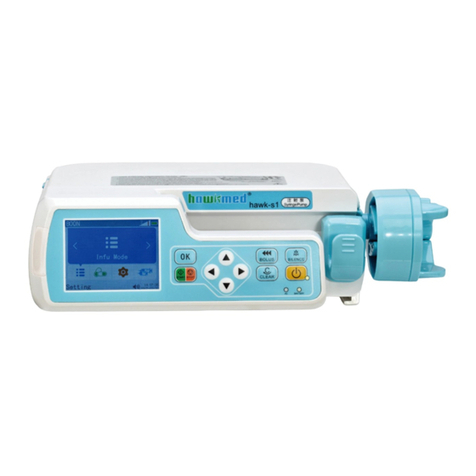
Hawk Hawk-i1 User manual

1
Hawk-i1 INFUSION PUMP
USER MANUAL
Version: V2.0.1
Shenzhen Hawk Medical Instrument Co. Ltd.
Please read the manual before using the product.
Please keep the manual for reference!
057-00088-00

2
Contents
REVISION NOTES:........................................................................................................1
1. WARNINGS AND CAUTIONS......................................................................................1
2. INTRODUCTION ........................................................................................................5
2.1 FEATURES.............................................................................................................5
2.2 MAJOR USES AND SCOPE OF APPLICATION....................................................................6
2.3 TYPE AND SPECIFICATION .........................................................................................6
2.4 PRODUCT MODEL ...................................................................................................6
2.5 OPERATING CONDITIONS...........................................................................................6
2.6 IMPACTS ON ENVIRONMENT AND ENERGY .....................................................................7
2.7 DATE OF MANUFACTURE &LIFE SPAN ...........................................................................7
2.8 VERSION OF SOFTWARE............................................................................................7
3. OPERATING PRINCIPLE AND CONSTITUENT PARTS..................................................7
3.1 OPERATING PRINCIPLE .............................................................................................7
3.2 CONSTITUENT PARTS ...............................................................................................7
4. TECHNICAL CHARACTERISTICS AND PARAMETERS.................................................8
5. INSTALLATION AND ADJUSTMENT............................................................................9
5.1 INSTALLATION CONDITIONS AND TECHNICAL REQUIREMENTS ..............................................9
5.2 INSTALLATION METHOD AND CAUTIONS..........................................................................9
6. APPEARANCE INTRODUCTION ...............................................................................10
6.1 FRONT VIEW ........................................................................................................10
6.2 OPERATION PANEL ................................................................................................10
6.3 SCREEN DISPLAY ..................................................................................................12
6.4 REAR VIEW .........................................................................................................13
6.5 LABEL ................................................................................................................14

3
7. PRECAUTIONS FOR PREPARATION AND OPERATION .............................................16
7.1 PREPARATION AND INSPECTION BEFORE USE ...............................................................16
7.2 OPERATION PRECAUTIONS ......................................................................................16
8. OPERATION METHOD .............................................................................................17
8.1 INFUSION OPERATION ..........................................................................................17
8.2 ALARMS AND SOLUTIONS ........................................................................................33
8.3 INFUSION TUBE SETTING.........................................................................................38
8.4 SYSTEM SETTING..................................................................................................40
8.5OPERATION PRECAUTIONS ......................................................................................47
8.6 CONTRAINDICATIONS:............................................................................................47
9. TROUBLESHOOTING ..............................................................................................47
10. SAFETY INVENTION AND TROUBLESHOOTING .....................................................49
10.1 SAFETY INVENTION AND PRECAUTIONS .....................................................................49
10.2 TROUBLESHOOTING .............................................................................................49
11. MAINTENANCE, INSPECTION, REPAIR AND RECOVERY ........................................49
11.1 ROUTINE MAINTENANCE ........................................................................................49
11.2 MAINTENANCE DURING OPERATION ..........................................................................49
11.3 REGULAR INSPECTION ..........................................................................................49
11.4 NORMAL REPAIR PROCEDURES ...............................................................................51
11.5 MAINTENANCE FOR LONG-TIME STORAGE................................................................51
11.6 RECYCLING........................................................................................................51
12. TRANSPORT AND STORAGE.................................................................................51
12.1 PRECAUTIONS DURING TRANSPORT .........................................................................51
12.2 STORAGE CONDITIONS .........................................................................................52
13. PACKAGE LIST .....................................................................................................52

4
13.1 STANDARD CONFIGURATION IN A PACKAGE:................................................................52
14. OPEN-PACKAGE INSPECTION...............................................................................52
15. AFTER-SALES SERVICE........................................................................................52
16. EMC INFORMATION ..............................................................................................53
17. LIST OF FACTORY DEFAULT PARAMETERS..........................................................59
APPENDIX 1 ...............................................................................................................59
TABLE 1CLASSIFICATION OF ALARMS AND COLOR OF ALARM INDICATOR LIGHT...........................59
TABLE 2ALARM CONDITIONS AND ALARM SIGNAL DELAY......................................................60
TABLE 3CHARACTERISTIC PARAMETER OF ALARM SOUND ...................................................61
TABLE 4OCCLUSION RESPONSE CHARACTERISTICS............................................................61
TABLE 5STARTING CURVE ...........................................................................................62
TABLE 6TRUMPET CURVES ..........................................................................................63
APPENDIX 2 FLOW ACCURACY TEST METHOD FOR INFUSION PUMP .........................64

1
Revision Notes:
The copyright of this user manual belongs to Shenzhen Hawk Medical Instrument Co., Ltd. No unit or
individual is allowed to copy, revise or translate this user manual without the consent of the company.
On the premise of comply with relevant laws and regulations, we’ll revise the manual timely according to
the improvement of products or update of laws and regulations.
This Manual applies to hawk-i1 infusion pump.
Version No.
Date of Preparation
V1.0.0
2017.05.24
V1.0.1
2017.08.23
V2.0.1
2018.04.04
User manual version upgrade instructions:
V X.Y.Z
V means version No. of user manual.
X means device has big upgraded: When software, hardware and construction of device have big
modified, the user manual should be upgraded accordingly.
Y means the device has small improvement: In order to better using the device, the software, hardware
and construction of device have been tiny improved ( it is not necessary for re-registration after
evaluation), the user manual should be upgraded accordingly.
Z means correcting information of user manual while the device has no changed. It only correct the wrong
word/ diagram/explanation and so on.
1. Warnings and Cautions
Warning

2
Personal casualties may be caused if precautions mentioned in this warning are violated.
A) The Infusion Pump uses peristaltic mechanism for medical fluid infusion, but cannot detect leakage
caused by disconnection or crack of infusion set. It is required to inspect the infusion status regularly
to prevent above problems.
B)During infusion process, please regularly check the status of dripping as well as the residual liquid
inside the infusion bag/bottle to ensure correct performance of the infusion. The Infusion Pump does
not directly measure quantity of fluid so it may not detect certain free flow in extremely special case.
Even equipped with drop sensor, the Infusion Pump may not detect free flow that smaller than certain
volume due to tolerance.
C) The Infusion Pump has occlusion detection function. It gives occlusion alarm when the infusion needle
fails to insert into intravenous vein properly or the needle deviates from its position inside the vein
during infusion. As occlusion alarm is given only after the occlusion pressure reaching a certain value,
the area around the needle may already become swollen or bleeding at this time. In addition, the
occlusion alarm is not given maybe because the actual occlusion pressure not large enough to reach
the occlusion alarm gate, therefore, it needs to check the insertion area regularly. If the insertion area
seems abnormal, please take proper treatments such as re-inserting the needle.
D) The user must install the infusion set straight and properly along the peristaltic fingers from left to right.
Otherwise, infusion may not reach expected performance.
E) Make sure the IV set is properly installed to the location of air bubble sensor and the occlusion sensor
(pressure detector). Air Bubble alarm or Occlusion alarm may not be given due to incorrect
installation of IV set.
F) Infusion flow blockage that caused by infusion set knotting, filter or needle blocking, or needle
occurring thrombosis etc. may lead to pressure increase inside the infusion set. Solving such
blockage may be followed by temporary large-volume infusion. The correct method is to clamp the IV
set near the insertion area tight before opening the pump door to release the pressure. Then release
the clamping of IV set, get rid of the occlusion problem and restart operation. If infusion restarting with
blockage remaining, occlusion alarm shall sound again and the pressure inside the tube may keep
increasing, which may result in disconnection or crack of the tube and further bring harm to the
patient.
G) Recommended that keep the flow clip of IV set in downstream position of the Infusion Pump. In case

3
of Air Bubble alarm, it is convenient for the user to clamp the flow clip and then squeeze the air
bubble back into the drip chamber.
H) Fix the Infusion Pump well to infusion stand/bar and also ensure the stability of the stand/bar. Be
cautious when moving the stand/bar and the Infusion Pump to prevent the Infusion Pump falling off or
the stand collision with surrounding objects.
I)The Infusion Pump cannot parallel use with gravity infusion device, as the machine can’t detect
downstream occlusion or empty of gravity infusion set.
J) The Infusion Pump cannot use with possible large negative or positive pressure piping such as
extracorporeal circuit. As in such case, the Infusion Pump cannot ensure infusion accuracy and
correct alarm functions.
K)The Infusion Pump cannot use for blood transfusion.
L) Please install the IV set in correct direction (from left to right). If installing in a wrong direction, patient’s
blood may be sucked out.
M) Do not use the Infusion Pump near inflammable liquid or gas.
N) Never store or use this infusion pump in places with chemical and active gas (including gases for
disinfection) or with much humidity, since it may affect the internal parts of infusion pump and finally
lead to degradation or damage of their performance.
O) This infusion pump cannot be directly powered by vehicle power supply.
P) Medical staffs should have regular patrol inspection, instead of relying on alarm system only, so as to
prevent accidents.
Q) Under single failure state, the maximum infusion quantity should be the remaining fluid in infusion
bottle/bag. Keep monitoring the operation state of system during infusion and check infusion pipe,
instead of relying on alarm function of this system.
R) Operator should not start infusion until the infusion parameters of infusion pump are conforming to the
medical advices. Any nonconforming setting of parameters may lead to invalid operation.
S) Make sure there is no water on the external wall of infusion pipe, especially make sure do not let water
flow to ultrasonic sensor; otherwise, it may fail to give alarm when there is bubble.
Cautions
Personal injury or property loss may occur if violating these precautions.
A) Inspect the Infusion Pump before use, making sure it can work normally. If any malfunction is found,

4
stop operation immediately and contact the distributor or the manufacturer. Besides, adhesion or
leakage of medical liquid may lead to malfunction of the Infusion Pump. Therefore please clean the
Infusion Pump and store it properly after each use.
B) When use the Infusion Pump the first time after purchasing or after long-time of storage, please
connect it to AC power source and charge it for at least 10 hours with power on, (or 3.5 hours with
power-off). If not fully recharged, the internal battery can’t support the Infusion Pump with enough
power in case of AC power failure.
C) If being used near electric cautery equipment, the pump may have misoperation due to the
high-frequency noise wave. The following steps and measures should be adopted if it is used
together with the medical electric burning device:
(1) Avoid using the Infusion Pump along with old-fashioned electric cautery apparatus (open vacuum
tube).
(2) The distance between Infusion Pump and the body of electric cautery apparatus or its power
source should be more than 25cm.
(3) Make sure power cables of electric burning device and infusion pump are induced from different
power distribution cabinets and they are reliably earthed.
D) Do not use mobile phone, wireless device or cardiac defibrillator within 1 meter near the Infusion
Pump. Otherwise the high frequency noise/signal may cause wrong performance of the Infusion
Pump. Make sure the Infusion Pump has ground connection and do not use the same power socket
with that for the above-mentioned devices.
E) The Infusion Pump cannot use in area with radiotherapy equipment or magnetic resonance (MR)
equipment or hyperbaric oxygen therapy.
F) Do not use pointed object like pen-tip or finger nail etc) to press on keys of the Infusion Pump.
Otherwise, the keys or the mask may suffer premature damage.
G) Keep the infusion bag, IV set and the Infusion Pump a certain distance from the AC power source and
DC socket to prevent the medical liquid from splashing or dropping onto the socket to incur shortage
of circuit. In addition, make sure the power plug and socket are dry before connecting to power
source.
H) Try to use the medical liquid when it reaches or near room temperature. If infusion with low
temperature fluid, the air dissolution inside the tube evaporate to many air bubbles, which cause

5
frequent Air Bubble alarms.
I) In normal conditions, try to use AC or DC power source to extend battery service life. When use AC
power source, making sure it is well connected to ground and please use the power cord that is
standard configuration with the Infusion Pump. Just use battery when there is difficulty in ground
connection or without AC power (such as AC power failure or mobile infusion).
J) Please do not use infusion pipe in the same pumping position for more than 6 hours (infusion pipe
replacement cycle for infusion at flow velocity below 1ml/h should be less than 24h). The infusion
pipe will deform and thus leading to flow error after long time use. It is suggested to move the infusion
pipe upward for 15cm every time after 6h (infusion pipe replacement cycle for infusion at flow velocity
below 1ml/h should be less than 24h) and then start infusion again, or replace with a new infusion
pipe.
K) To prevent free flow after door open please make sure to close the flow clip of IV set before taking it
out of the Infusion Pump.
L) Pay more attention to occlusion when infusion at low rate. The lower the rate, the more time needed
for detecting occlusion, thus there may be a long interval of infusion interruption.
M) When using computer port, it may suffer interference from devices such as electric cautery apparatus,
mobile phone, wireless device or cardiac defibrillator etc. Please try to keep away from the
above-mentioned devices.
N) If Infusion Pump falling off or suffering collision, stop using it immediately and contact the distributor or
the manufacturer. Even there is no damage on appearance or no malfunction alarm, the internal parts
may have damaged.
O) The Infusion Pump must be operated by well-trained professionals such as doctor, nurse and medical
device expert.
P) Do not disassemble or modify the Infusion Pump or use it for other purposes other than normal
infusion. Otherwise, the manufacturer takes no responsibility.
2. Introduction
2.1 Features
User friendly interface, easy operation
8 occlusion level adjustable

6
Large memory function
Multiple infusion modes to meet clinical requirements
Double CPU for safe infusion
Stackable feature to save space
2.2 Major Uses and Scope of Application
It is applicable to constant-speed intravenous infusion to patients in hospital.
2.3 Type and Specification
This product belongs to classⅠ, type CF. It is volumetric Infusion Pump on continuous operation and
with internal battery. It cannot be carried by patient for mobile use. It can’t be used in mixed gases of
flammable anesthetic gas with air, or of oxygen or nitrous oxide with flammable anesthetic.
2.4 Product Model
hawk-i1
Model
hawk-i1
Features
Infu Mode
1.Rate Mode
2.Time Mode
3.Weight Mode
4.Shift Mode
5.Program Mode
6.TPN Mode
7.Drip Mode
8.Intermittent
Can be stacked to double
channel, three channel, four
channel, five channel, six
channel, six channel, seven
channel, eight channel
infusion pump
2.5 Operating conditions
(1) Temperature: 5℃-40℃
(2) Relative humidity: 10%-85% (no frosting)
(3) Atmospheric pressure: 86.0kPa~106.0kPa

7
2.6 Impacts on Environment and Energy
This infusion pump may have certain electromagnetic radiation and interference on other devices.
Such interference, if occurred, should be alleviated by adopting certain measures, such as
rearranging position of infusion pump or inducing mains supply from different positions. For more
information, please see Part 17 –Electromagnetic Compatibility (EMC) Information” of this Manual.
2.7 Date of manufacture & life span
The life span of the infusion pump (battery is not included) and its cable is 5 years. Please refer to
label for date of manufacture.
2.8 Version of software
The version of the user manual for infusion pump’s software is V01.
3. Operating Principle and Constituent Parts
3.1 Operating Principle
This infusion pump is a kind of instrument that drives pump tablet to squeeze infusion pipes in
sequence with its motor to control accurate drop number or infusion speed, ensure uniform liquid
flow and enable drugs to enter patient’s veins correctly and safely so as to take effect.
3.2 Constituent Parts
The infusion pump is mainly composed of microcomputer system, pump, detection device, alarm
system and HMI.
Microcomputer system: the brain of the whole system, giving an intelligent control and management
to the whole system and processing signals detected, adopting double CPU;
Pump body: the heart of the whole system and the driving force of transfusing medical liquid,
squeezing medical liquid forward along peristaltic fingers driven by step motor.
Detection device: mainly containing sensors, such as ultrasonic sensor (for detecting air bubble in
line) and pressure sensor (for detecting occlusion) etc. They can detect corresponding signals,
which after being amplified and transferred to microcomputer system for signal processing and thus
incur control instruction for corresponding operation.
Alarm system: The signals detected by the sensor, after being processed by the microcomputer,
shall incur alarm control signal and then at the response of alarm system, which alert the user for

8
immediate correct operation. It contains mainly photoelectric alarm (light emitting diode ) , audible
alarm (loudspeaker and buzzer) and screen display alarm;
HMI: to set parameters of infusion through keys, such as infusion volume and speed. It can display
all parameters and current working state through color LCD.
4. Technical Characteristics and Parameters
Parameters
Description
Applicable infusion set
(1) 15 drops/ml, 20 drops/ml,60 drops/ml infusion set
(2) Hawkmed dedicated infusion set (1ml=20 drops, optional)
Infusion accuracy
±5% (dedicated set ±3%, 10-35℃, test volume 2ml)
Infusion rate
0.1-1200ml/h, increment 0.01ml/h
Dripping rate
0-400 drops/min
Preset value
0-9,999.9ml, increment 0.01ml
Volume infused (∑)
36,000ml
KVO rate
(0-10) ml/h, increment 0.01
Bolus
(0.1-1200)ml/h
Purge
1200ml/h
Occlusion pressure
10.0-160.0kpa, 8 level adjustable
Low battery alarm limit
Voltage of internal batteries is lower than 7.1V
Battery exhausted alarm limit
Voltage of internal batteries is lower than 6.65V
SPL (sound pressure level) of
alarm signal
SPL of alarm signal not lower than 45dB(A) at low grade
SPL of alarm signal not lower than 65dB (A) at high grade
Waterproof level
IPX3
AC power supply
100-240V 50/60Hz

9
Internal battery
Li_Polymer 7.4V 1900mAh;
Recharge time: 10h with power on, 3.5h with power off.
Running time: more than 10h at rate of 25ml/h, environment
temperature 25℃after being fully charged.
Charging and discharging cycle: more than 300 cycles
DC
DC12 ± 1.2V, 1.5A, CE certified
Power consumption
25VA
Fuse
Slow fuse Specification: 250V 2A
(Maximum fusing time is 10 seconds when current
is 5.5A)
Dimensions
212*138*80 (L*W*H )mm (Pole clamp excluded)
Weight
1.4Kg
5. Installation and Adjustment
5.1 Installation conditions and technical requirements
The Infusion Pump can be fixed to a vertical IV pole with diameter of 12-35mm, or on platform with
slope angle not exceeding 5°.
5.2 Installation method and cautions
Method 1: Put the infusion pump on stable platform
Method 2: Fix the infusion pump to IV Pole as per below steps:
(1)Rotate the clamp knob of fixation screw out the rod, leave space for IV pole
(2)Clamp to IV pole (the IV pole should meet the requirements of balance and mechanical strength),
screw down the knob to fix the position of infusion pump. Should hold the infusion pump during
the installation; only release the hand after screwed tightly to avoid falling.
Remark: Mechanical strength of IV pole: yield strength≥170MPa, tensile strength≥480MPa,
load-bearing requirement≥13kg , verticality of IV pole≤5°。

10
6. Appearance Introduction
6.1 Front View
(Diagram 1: Front View)
6.2 Operation Panel

11
Description
Function
Silence key
Press this key to silence the alarm sound. The visible alarm info can’t be
removed by SILENCE key
Power key
Switch on / off the infusion pump.
1.Switch on: in ‘power off’ status, keep pressing this key until LCD screen
displays, and the indicator light is on .
2.Switch off: in ‘switch on’ status, keep pressing this key until hear a sound
“beep” and the indicator light is off.
BOLUS key
In ‘stop’ status, keep pressing ‘BOLUS’ key, the pump starts purging; release
this key, purge stops.
During operation, keep pressing ‘BOLUS’ key, the pump starts
bolus infusion (bolus rate preset by the user). Release the key,
bolus infusion stops and the pump continues infusion at original
rate.
Clear/back key
1. Clear the alarm for both sound and visible info
2. Back to the previous menu
OK key
1. To select the parameter and make it editable
2. Save the setting value
Start key
In ‘stop’ status, press this key to start infusion.
Stop key
Press this key to stop infusion.
Door open key
Under shutdown status, press this key to open the door and switch on the
machine at the same time. This key is invalid during infusing.
AC/Battery
Indicator light
If on, it indicates there’s AC/DC input;
if off, it indicates there’s no AC/DC input.
Indicator light
1. Indicator light indicates operating status/alarms cases.
2. If the IV set is installed correctly and with no air in line, the indicator light
shall be green after the door is closed, which also indicating the pump is
ready for starting infusion.
3. The green indicator light flashes when the infusion is in normal progress.
4. If high-priority alarm occurs during operation, the indicator light shall turn
red and flash.
5. If middle-priority alarm occurs during operation, the indicator light shall
turn yellow and flash.
6. If low-priority alarm occurs during operation, the indicator light shall turn

12
yellow but not flash.
* Please refer to Annex I Table 1 for priority of alarm classification.
Charging indicator
light
This indicator light on means the battery is recharging.
This indicator light off means the battery is not charging.
(Up key)
(Down key)
1. When selecting the parameters, press the keys to previous or next
parameter.
2. When setting the value, press this keys to increase or decrease the value.
(Left key)
(Right key)
1. When selecting the parameters, press the keys to left/right parameter, or
previous/next page.
2. When setting the parameters, press the keys to move left/right
6.3 Screen Display
(Diagram 2: Screen Display)
Battery icon :
1).Green wave appearing indicates the battery is charging
2).The battery icon indicates status of battery remaining capacity.
3) If the icon of battery is in red, then the battery is damaged or not connected with battery
Pressure indicating icon :

13
(1) Except for the first vertical line, the lines from the left to the right are corresponding to 8 levels of
occlusion. The red one means the preset occlusion level.
(2) Pressure indicating icon shows the pressure in tube. With the changing of pressure in infusion tube,
pressure indicating icon will appear green surge wave. When the green wave reaches or passing
the red vertical line, the infusion pump will give occlusion alarm. This icon just show the pressure
changing in the infusion set, not the alarm signal.
6.4 Rear View
(Fig. 3 Rear View)
Description
Function
Battery cover
The lithium battery is installed inside and it is opened from
bottom case.
Pole clamp
To fix infusion pump on IV pole
Socket of network power supply
To connect with external 100V-240V 50/60Hz AC power supply

14
USB Port
Used for upgrading software or transferring infusion history
records. Connect with the PC according with the standard of IEC
60950-1-2005 Information technology equipment - Safety -
Part 1: General requirements to output infusion records to PC.
Note: This process must be carried out when machine in
non-infusion state.
DC12V
/Drop sensor port
This port for DC12V; Drop sensor port works with Hawkmed
drop sensor only.
Link interface
Used to connect with Hawkmed workstation
6.5 Label
6.5.1 Product label (on the back shell)
The label contains information such as manufacturer, date of production, product serial No.,
classification, waterproof level, etc.
6.5.2 Symbols and significance
(Table 1)
Symbols
Descriptions
Production batch No.
Product serial No.
Caution, consult accompanying documents
Please refer to instruction manual
Type CF
Protective Earthed

15
IPX3
Waterproof level: dripping water by slope angel 60°
AC power
DC power
Dispose in environmental-friendly way
Date of manufacture
Manufacturer
Stop action
/
Turn on/off
Silence alarm sound
Caution Against Wet
Fragile. Handle with care!

16
Keep upright during transport
5 layers at most of the same package
Transport package humidity 10 ~ 95%
Transport package temperature -20°C ~ 45°C
7. Precautions for Preparation and Operation
7.1 Preparation and inspection before Use
Whether the Infusion Pump is a new one, or it has been stored for a period of time, or it just has been
repaired, please check the following terms before use:
(1) The outlook remains good, clean, no crack and no leakage
(2) All keys are responsive. No invalid key or stuck key.
(3) The door opens agilely and can be closed tight.
(4)Device cannot be placed in places where it may be crushed; The power cord can be plugged in
tight, not easy to pull off.
(5) If Infusion Pump worked on internal battery only, charge it fully before use and also make sure the
battery is still valid for use.
(6) Set and check system time to make sure the history events are recorded correctly.
(7) Please read the precautions and operation steps of this user manual carefully
7.2 Operation Precautions
(1) It should be free from direct sunlight, high temperature or high humidity.
(2) Do not run the infusion pump with malfunction to avoid medical accident and endangering the
patients.
Table of contents
Other Hawk Water Pump manuals