89
Assembly
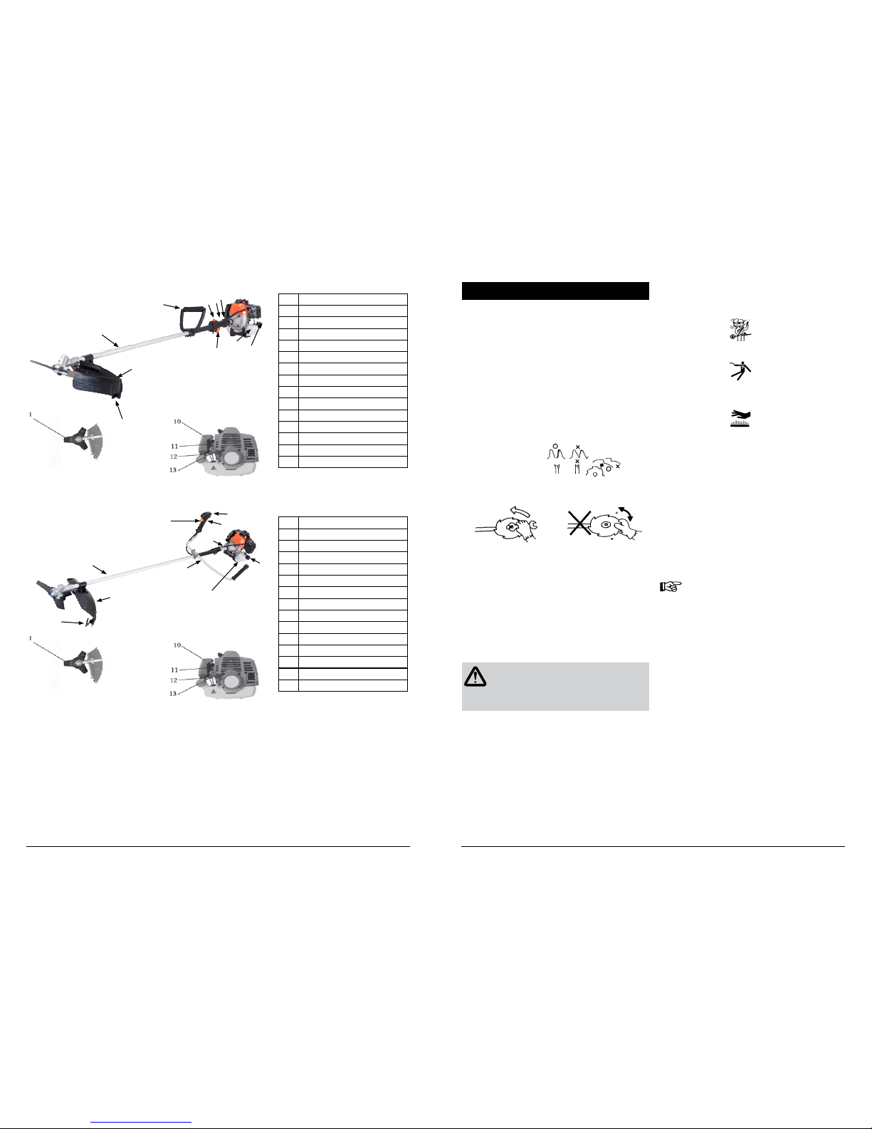
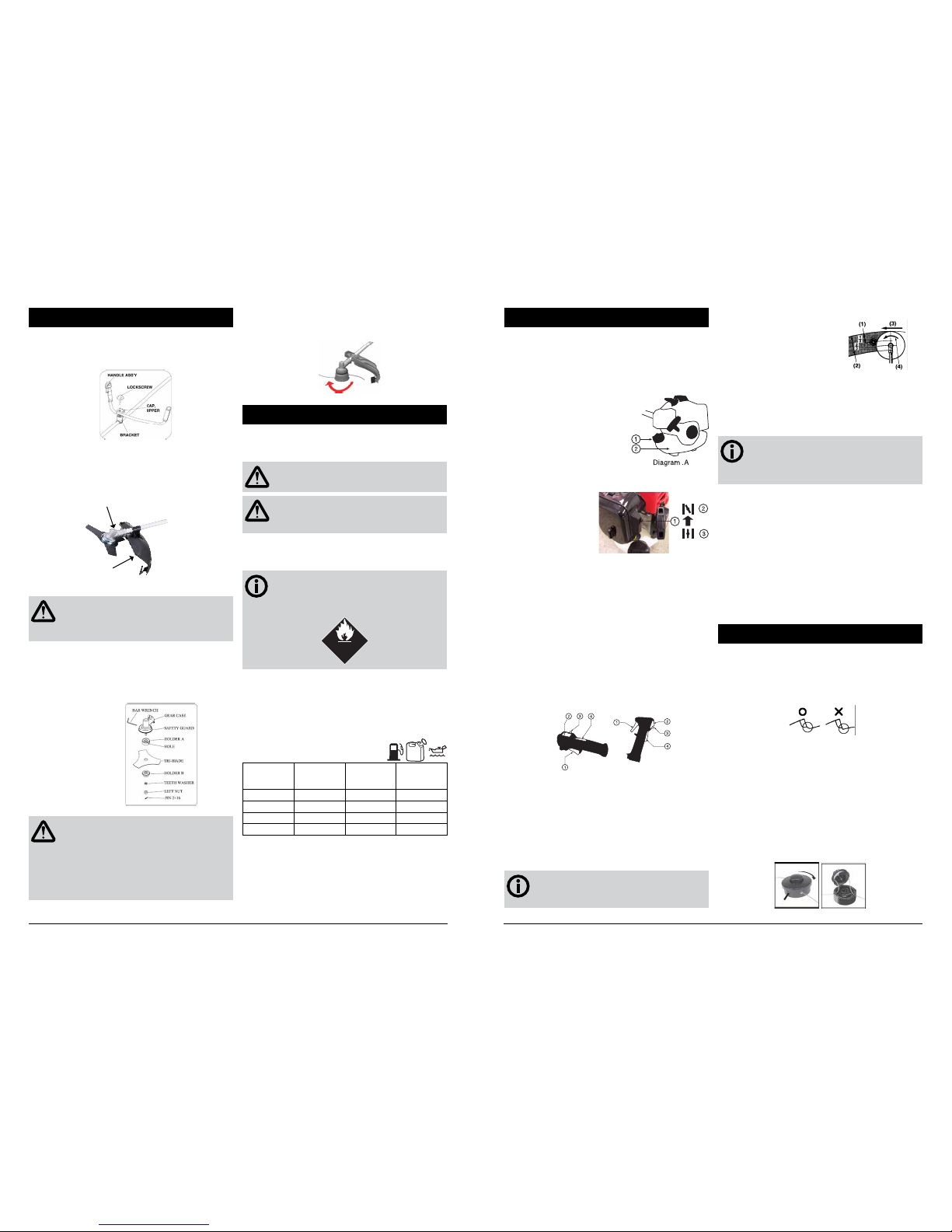
BCL 440 INSTALLING THE HANDLE BARS
Install the handle in bracket. Place handle in a comfortable operating
position and tighten lockscrew.
INSTALLING THE SAFETY GUARD
Install the safety cover on the shaft with the safety cover bracket and the
screws provided.
Tighten the screws after setting the safety cover bracke at the appropriate
position.
GEAR CASE
SHIELD
WARNING!
Do not operate this unit without a safety guard, if the safety
guard is damaged replace immediately. Do not continue with
a damaged guard.
INSTALLING THE BLADE
Install holder A, the tri-blade, holder B, and teeth washer, in this order, and
then clamp with a left-hand thread net.
Align hole of gear case and holder A, and insert S=4mm bar wrench.
Rotate blade-fastening nut with plug box wrench in counter clockwise
direction until securely tightened.
Install the pin 2x6 and disjoin it.
WARNING!
EXCESSIVE VIBRATION - STOP ENGINE IMMEDIATELY
Excessive vibration of the blade means that it is not properly
installed. Stop engine immediately and check blade. Blade
not properly installed can cause injury.
Use only original cutting equipment parts when servicing the
unit.
INSTALLING THE NYLON CUTTER HEAD
Align hole in adapter plate with hole in shaft and install locking tool.
Thread cutter head onto shaft (turning it clockwise) until it is tight. Remove
locking tool.
Fuel
1. Petrol is very flammable. Avoid smoking or bringing any flame or
sparks near fuel.
2. Wipe up all spills before starting the engine.
WARNING!
Stop the engine and allow it cool before refuelling the unit.
WARNING!
Keep open flames away from the area where fuel is handled
or stored.
3. Use only oil intended for 2 stroke air cooled engine use. Other oils
can cause spark plug fouling, exhaust port blocking, or piston ring
sticking.
IMPORTANT!
Fuel mixtures which have been left unused for an extended
period may clog the carburettor or cause hard starting. Store
unused fuel in an air-tight container in a cool place.
E
FUEL
FLAMMABLE
FUEL
4. Fuel mixtures which have been left unused for an extended period
may clog the carburettor or cause hard starting. Store unused fuel in
an air-tight container in a cool place.
5. Mix a regular grade petrol (leaded or unleaded) and a good quality
two stroke engine oil for air cooled engines. Shake them together in
a clean container to ensure thorough mixing before pouring into the
fuel tank. Do not use plastic containers not specifically designed for
use with petrol.
6. Mixing ratio chart:
Unleaded
Gasoline
2 cycle
mineral oil
25:1
2 cycle semi-
synthetic oil
40:1
2 cycle
synthetic oil
50:1
1 L 40mL 25mL 20mL
4 L 160mL 100mL 80mL
5 L 200mL 125mL 100mL
10 L 400mL 250mL 200mL
FUEL
1L
liOl m04
Operating
STARTING THE ENGINE
Before starting the engine, inspect the entire unit for loose fittings or fuel
leaks, and verify that the cutting attachment is properly installed and
securely fastened.
Place the unit on a flat, firm place. Keep the cutting head clear of any
obstructions.
1. Check that there is fuel in the tank and that the fuel cap is screwed
on tightly.
1) Cap
2) Fuel tank
2. When starting a cold engine move the choke lever (behind the air
cleaner cover) to the closed position.
1) Choke lever
2) Closed
3) Open
3. If the engine has been running and is still warm, move the choke
lever to the open position.
4. Press the priming bulb under the carburettor repeatedly until excess
fuel can be seen returning to the tank through the clear fuel return
pipe.
5. Slide the ignition switch (3) on the trigger grip away from the STOP
position (See Diagram .C on the next column).
6. To set the throttle in the start position.
- Depress the safety lever (4)
- Squeeze the throttle lever (1) fully.Hold down the starting button
(3) while releasing the throttle lever.
- The throttle lever will be held partly open until it is squeezed again.
1) Throttle lever
2) Ignition Switch
3) Starting button.
4) Safety Lever
Diagram .C
7. While holding the unit firmly, pull out the starter rope quickly.
8. After the engine has started, open the choke gradually.
9. Allow the engine to run for 2 to 3 minutes to warm up before
starting work.
STOPPING THE ENGINE
1. Release the throttle lever.
2. Slide the ignition switch on the trigger grip to the STOP position.
FITTING THE HARNESS
IMPORTANT!
The harness must always be used as the machine cannot be
operated safely without it.
Diagram .B
CUTTING USING THE METAL BLADE
1) For shrubs & thick weeds
2) For grass and weeds
3) Direction of cutting
4) Direction of rotation
1. A metal blade cuts best with a swathe up to one third of the cutter
diameter. Use that area for cutting shrubs, tough and thick weeds.
For cutting young grass, you can use up to two thirds of the cutter
diameter.
2. Adjust the engine speed according to the material being cut. Cut the
young grass at middle speed, and shrubs or tough and thick weeds
at high speed.
IMPORTANT!
If the cutting speed is too low, debris can be caught
up in the blade, and if this causes the clutch to slip it
will wear out quickly.
CUTTING WITH THE NYLON CUTTER
• Cutting with the nylon cord consumes more power so the
engine speed should be 50% greater than when using the
metal blade.
• The nylon cord cuts the grass by meeting it at high speed. If you take
too wide a swathe you may slow down the engine and not get clean
cutting. To correct this, retract the cutter from the grass until the
engine regains full speed and then cut using a narrower swathe.
• After a time the nylon cord will wear away. To restore the full cutting
diameter, simply bump the cutter head on the ground while it is
running at full speed. The cords will extend automatically and will be
trimmed to the correct length by the cord trimmer blade mounted on
the guard.
• Cut grass by swinging the brushcutter from left to right. While
you can cut in either direction, if you follow these suggestions the cut
grass will be thrown away from you, and you will avoid getting your
clothes dirty.
Maintenance
BLADE
• Sharpen each cutting edge and make sure the inside corner is
rounded to reduce the risk of cracking.
• Do not quench the blade with water if you are using a grinder as it
may start cracks in the blade.
• The 3 tooth blade may be inverted to utilise a fresh set of cutting
edges.
NYLON CUTTERS
The spools of nylon cord inside these bump-feed cutter heads will
eventually need replacing. While the change can be made with the cutter
head on the machine, it will be more convenient to remove the cutter
head.
CHANGING THE SPOOL
Push the locking latch located laterally on the spool housing (see picture,
action 1). Then turn the cover clockwise by about 1.5 cm (see picture,
action 2). This will unlock the cover and it can be removed. Now remove
the Tap’n go button and then the used-up spool from the spool housing.
Pass the two line ends of the new spool th rough the eyelets in the spool
housing as shown in the picture . The line ends still stay clamped in the
two transpo rt clamps pf the spool.