Masport MT23HM/B User manual

554282 - Masport Brushcutter OM - July 2010
IMPORTANT: Keep these instructions and the engine booklet in a safe place for future reference.
They contain important information about your brushcutter.
Brushcutters
OWNER’S
MANUAL
This manual covers the models: MT23HM/B, MT23HM, MT27M, MT27K, MT27H,
MT36K & MT36H. Some features mentioned may not apply to your brushcutter.
Part No: 554282

2
554282 - Masport Brushcutter OM - July 2010
3
About this Manual
Thank you for purchasing this product. This instruction manual describes operating procedures and precautions as well
as inspection and maintenance procedures for the machine.
Before using this device, read this manual carefully until you are familiar with the contents. Carefully observe all
warnings and safety instructions to ensure correct operation of the machine. Doing so will ensure safe operation and
optimum performance of the device.
This manual contains information applicable to several models of the machine. Before reading this manual, identify the
model of the machine and the engine mounted on it. Also refer to the separate instruction manual for your engine.
Be sure to strictly observe the important safety information that follows each bulleted term below. Failure to follow the
instructions for correct operation contained herein can result in a severe accident.
NOTICE This is an auxiliary explanation that provides useful information and instructions.
zAfter studying this manual, keep it handy for easy reference.
zIf this manual is lost or damaged, immediately order a new copy from your dealer.
zIf lending or transferring the machine to a third party, be sure to include this instruction manual and to instruct the
third party to read the manual carefully before operating the device.
zProduct specifications are subject to change without notice in the interests of improved product quality or
performance or to enhance product safety. The descriptions and illustrations contained in this manual might differ
somewhat from the machine.
zIf you find any part of this manual to be unclear or confusing, contact your dealer.
Contents
Technical Data
Meanings of pictographs
[1] Names of Parts
[2] Safety Instructions
[3] Ensuring Safe Operation
[4] Fuel and Oil
[5] Assembly
[5-1] Mounting the cutting attachment guard
[5-2] Mounting the cutting blade or nylon trimmer
[5-3] Attaching the handle, throttle linkage, and cord
[6] Starting and Stopping the Engine
[7] Wearing the Harness
[8] Inspection and Maintenance
[9] Long-term Storage
[10] Troubleshooting
・DANGER: Indicates that failure to follow the instructions creates an imminent hazard leading to death
orsevere injury.
・WARNING: Indicates that failure to follow the instructions has the potential to result in death or severe injury.
・CAUTION: Indicates that failure to follow the instructions can lead to minor injury or severe damage to the
machine.
1
2
5
7
8
8
9
11
12
16
18
22
23
・・・・・・・・・・・・・・・・・・・・・・・・・・・・・・・・・・・・・・・・・・・・・・・・・・・・・・・・・・・
・・・・・・・・・・・・・・・・・・・・・・・・・・・・・・・・・・・・・・・・・・・・・・・・・・・・・・・・
・・・・・・・・・・・・・・・・・・・・・・・・・・・・・・・・・・・・・・・・・・・・・・・・・・
・・・・・・・・・・・・・・・・・・・・・・・・・・・・・・・・・・・・・・・・・・・・・・・・・・・・・・・・・・・・・・
・・・・・・・・・・・・・・・・・・・・・・・・・・・・・・・・・・・・・・・・・・・・・・・・・・・・・・・・・・・・・・・・
・・・・・・・・・・・・・・・・・・・・・・・・・・・・・・・・・
・・・・・・・・・・・・・・・・・・・・・・・・・・・
・・・・・・・・・・・・・・・・・・・・・・・・・
・・・・・・・・・・・・・・・・・・・・・・・・・・・・・・・・・・・・・・・・・・・
・・・・・・・・・・・・・・・・・・・・・・・・・・・・・・・・・・・・・・・・・・・・・・・・・・・・・・
・・・・・・・・・・・・・・・・・・・・・・・・・・・・・・・・・・・・・・・・・・・・・・・・
・・・・・・・・・・・・・・・・・・・・・・・・・・・・・・・・・・・・・・・・・・・・・・・・・・・・・・・・
・・・・・・・・・・・・・・・・・・・・・・・・・・・・・・・・・・・・・・・・・・・・・・・・・・・・・・・・・
5
6-8
9
11
12
12
13
15
16
20
22
26
27
................................................... 4
. ........................................................... 3
in a safe place and handy for easy reference.
possible death or severe injury.
may differ

3
554282 - Masport Brushcutter OM - July 2010
MT23HM/B MT23HM MT27M MT27K MT27H MT36K MT36H
HM23K-10B HM23K-10 TU26PFD TJ27E GX25T TJ35E GX35T
kg 3.9 4.0 5.5 5.4 5.9 7.5 8.4
kg 4.4 4.4 5.8 6.0 6.5 8.2 8.9
kg 4.7 4.7 6.3 6.4 6.9 8.7 9.4
36.07.085.05.06.04.04.0lemuloV
Nylon trimmer Nylon line diameter mm
Specified blade diameter mm
Specified blade thickness mm
Number of cutting teeth
mm
min-1
Seen from above clockwise
mm 1480 1740 1835 1835 1875 1850 1875
mm 225 230 395 395 395 690 690
mm 485 210 280 290 305 520 520
cm322.2 22.2 25.6 26.3 25.0 34.4 35.8
kW 0.74 0.74 1.03 0.77 0.72 1.03 1.0
min-1 8000 8000 7500 7500 7000 7000 7000
min-1 8000 8000 8000 8000 8000 8000 8000
min-1 5900 5900 5900 5900 5900 5900 5900
min-1 2800 2800 2800 2800 2800 2800 2800
min-1 3800 3800 3800 3800 3800 3800 3800
dB 77 77 73 76 73 77 73
dB 100 96 95 96 94 99 96
dB 84 84 81 87 83 87 86
dB 111 107 104 106 106 110 109
dB 113 109 106 107 107 111 110
m/s22.3 4.6 3.6 7.7 4.2 2.3 2.2 4.4 1.8 2.4 2.7 4.0 1.7 3.0
m/s27.8 6.3 10.1 7.4 6.1 7.6 6.2 12.2 7.5 7.7 5.6 5.0 5.6 4.8
m/s25.7 5.5 7.6 7.5 5.2 5.6 4.6 9.2 5.4 5.7 4.4 4.5 4.1 4.0
Racing (R L)
Equivalent vibration total values (R L)
Blade
3.02.4
Idling (LWI)
Racing (LWR)
Guaranteed sound power level (LWA)
Idling (R L)
Recommended engine idling speed
Engine speed at beginning of clutch
engagement
Idling (LPI)
Racing (LPR)
Maximum shaft brake power,measured in accordance with ISO 8893
Engine speed at maximum power
Recommended maximum engine speed
Output shaft speed
Length
Width
Height
Engine displacement
8000
Seen from above anti clockwise
1.36
Cutting attachment
Center hole diameter
Rotational speed at maximum allowed engine
speed
Gear ratio
Rotational direction of output shaft
3 , 4 or 8
25.4
1) Reference for the harmonized standard ISO 7917
2) Reference for the harmonized standard ISO 10884
3) Reference for the harmonized standard ISO 22867
External
dimensions
Masses
Vibration levels 3)
Rotational
speeds
Sound pressure
levels 1)
Sound power
levels 2)
Unit without cutting attachment,
empty tank
Unit with specified cutting attachment, empty
tank
Unit with specified cutting attachment, full tank
Technical Data
230 255
1.4
Model
Engine
Handle type eldnah elbuoDeldnah pooL
Fuel tank

4
554282 - Masport Brushcutter OM - July 2010
4
Meanings of pictographs
DANGER - WARNING - CAUTION
Never attempt to mount a saw blade on this brushcutter.
Do not operate the device within 15 meters of a child, animal, or
bystander.
Wear safety gear.
1. Face shield or protective goggles
2. Head protection
3. Ear protection
4. Heavy-duty gloves
5. Non-slip safety shoes
Before using this device, read this manual carefully until you are
familiar with the contents.
Do not refuel or operate the machine near open flame.
Watch out for objects thrown from the brushcutter.
Do not run the engine in a room or in any confined area where
exhaust emissions can accumulate.
Never touch the spark plug cap or high-voltage wire while the
device is running.
Do not touch metal parts that can become very hot during and
immediately after device operation.

5
554282 - Masport Brushcutter OM - July 2010
- 1 -
[1] Names of Parts
1. Engine
2. Spark plug
3. Air cleaner cover
4. Fuel tank cap
5. Muffler
6. Throttle linkage
7. Clutch case
8. Control handle
9. Throttle trigger
10. Throttle trigger lockout
11. Stop switch
12. Suspension point
13. Loop handle
14. Shaft tube
15. Cutting attachment guard
16. Angle transmission
17. Blade
18. Nylon trimmer
19. Skirt
20. Blade cover
21. Harness
22. Shaft case
1
18
14
3
2
5
4
15
7
8
9
13
11 10
12
16
6
1
17
14
3
2
5
4
15
7
8
9
13
11 10
12
16
6
MT27M
MT27K
MT27H
21
MT23HMB
MT23HM
MT27M
MT27K
MT27H
MT36K
MT36H
20
18 19
MT36K
MT36H
1
17
8
9
14
3
2
11 5
4
10
15
7
12
16
6
1
18
14
3
2
5
4
15
7
8
9
13
11 10
12
22
6
MT23HM
MT23HM/B
Disposal of Packaging
Remove all protective packaging. Make sure you properly dispose of, or recycle the packaging materials where possible.
Comply with the applicable waste disposal laws in your area.

6
554282 - Masport Brushcutter OM - July 2010
- 2 -
[2] Safety Instructions
1. About This Manual
CAUTION
This manual contains important safety instructions.
Before using this device, read this manual carefully until
you are familiar with the contents. Carefully observe all
warnings and safety instructions to ensure correct
operation of the machine. Doing so will ensure safe
operation and optimum performance of the device.
CAUTION
This instruction manual does not cover all possible
situations and conditions. Although we have taken all
possible steps to ensure the safety of this device, the
operator and the person performing maintenance of the
device must also take all possible steps to ensure safety.
2. Recommended Uses
CAUTION
Use this brushcutter only to cut weeds or brush below
your knee height. Do not use it for delimbing, bucking or
felling of trees.
3. Safe Practices
CAUTION
Follow local noise regulations regarding the acceptable
times and locations for using this device. Also observe
current local safety regulations, standards, and ordinances.
4. Replacement Parts
WARNING
To maintain optimal safety and performance, use only the
manufacturer’s genuine parts and accessories. Do not
modify the device or use it for purposes other than those
specified. Failure to observe this requirement can result in
severe accidents and damage to the device.
5. Never use a saw blade
CAUTION
Never attempt to mount a saw blade on this brushcutter; it
is not designed to use a saw blade. The cutting attachment
guard for this device does not meet the safety standard for
a saw blade; therefore, thrown objects can cause injury.
6. Operator Safety
WARNING
Do not operate this device if you…
• cannot concentrate due to fatigue, illness, or injury;
• are under the influence of drugs or alcohol;
• are under the age of 15;
• are pregnant.
If any of the above applies, a possible lack of judgment
can result in an accident.
7. Monitor the weather
WARNING
Do not operate the machine under any of the following
circumstances:
• When the ground is slippery or you cannot maintain a
stable posture for any reason.
• At night, in heavy fog, or at any other times where your
field of vision is limited and it is difficult to gain a clear
view of the working area.
• During rainstorms, thunderstorms, in strong or gale-
force winds, or in any other adverse weather in which use
of this device would be unsafe.
8. Using Safety Gear
WARNING
Always wear proper clothing when using this device.
• Tight-fitting, safe, and non-restricting clothing including
a long-sleeved shirt and a pair of trousers. (Avoid wearing
shorts or baggy clothing.)
Loose-fitting clothing can become entangled in a tree
branch or the like, posing the risk of tripping and
resultant injury.
• Ear protection to protect your hearing
• Face shield or protective goggles
• Heavy-duty gloves
• Non-slip safety shoes (Never operate this device while
barefoot or when wearing sandals.)
• Head protection to protect your head from thrown
objects, etc.
Fig.2-4
Fig.2-1
Fig.2-2
Fig.2-3

7
554282 - Masport Brushcutter OM - July 2010
- 3 -
9. Basic Operations
CAUTION
• To ensure safe operation of this device, become familiar
with the safety instructions and the procedure for shutting
off the engine. (See [6] Starting and Stopping the
Engine.)
• In an emergency, it may be necessary to quickly release
the machine from your body; therefore, familiarize
yourself with the correct use of the harness quick release
mechanism. (See [7] Wearing the Harness ●Quick-
release mechanism.)
10. Cutting Attachment Guard
WARNING
Never operate the brushcutter without the cutting
attachment guard properly installed. (See [5-1] Mounting
the cutting attachment guard.)
The cutting attachment guard protects the operator from
thrown objects and prevents the cutting attachment from
contacting the operator. If the cutting attachment is not
properly installed, a thrown rock can cause death or
severe injury.
11. Fuel Handling Precautions
DANGER
• Do not operate the machine near open flame or spilled
fuel.
• Do not refuel while the engine is running or while the
engine is still hot after shutting off the machine.
• Do not refuel while smoking.
• Thoroughly wipe away any spilled fuel after refueling.
• Start the engine at a location at least 3 meters away from
the refueling area or the fuel container. Fuel is highly
inflammable, and a fire can lead to death or severe injury.
12. Exhaust Gas Precautions
DANGER
Do not run the engine in a room or in any confined area
where exhaust emissions can accumulate. Doing so can
result in an accumulation of carbon monoxide and other
poisonous gases that can cause death or severe poisoning.
13. Cutting Blade Precautions
DANGER
• Do not approach the running blade or nylon trimmer
with your hand or foot.
• If long grass or any other object becomes entangled in
the cutting blade or nylon trimmer, shut off the engine
and wait for the cutting blade or nylon trimmer to stop
completely.
• Wear heavy-duty gloves and use caution when handling
the stopped blade. The cutting blade is very sharp and can
cause death or severe injury.
14. The Hazard Area
WARNING
• Do not operate the device within 15 meters of a child,
animal, or bystander. Consider a 15-meter radius around
the device to be a “hazard area.”
• If someone approaches the hazard area, immediately
shut off the engine. A running machine can eject debris or
gravel at a speed that can cause death or severe injury.
15. Limit your worktime
WARNING
• Do not operate the machine for more than 2 hours a day.
• Rest for 10 to 20 minutes after every 30 to 40 minutes
of operation.
Continuing to operate the brush cutting without a break
can result in excessive fatigue. The resulting loss of
attentiveness can lead to an accident or problems with
your fingers or hands. If you experience any abnormal
symptoms such as pain, discomfort, or paralysis of the
fingers or hand, immediately stop operating the machine
and seek medical attention.
Fig.2-5
Fig.2-6
Fig.2-7

8
554282 - Masport Brushcutter OM - July 2010
- 4 -
16. Avoiding Electric Shock
WARNING
Never touch the spark plug cap or high-voltage wire
while the device is running. Doing so can result in a high-
voltage electric shock that can cause death or severe
injury.
17. Avoiding Burns
CAUTION
Never touch the muffler, muffler cover, exhaust pipe,
cylinder or cylinder head while the machine is running or
immediately after operation, as they become very hot.
Doing so can cause burns.
18. Using the Blade Cover
CAUTION
• Before transporting the brushcutter, shut off the engine
and mount the blade cover around the cutting blade.
Transport it with care.
• If transporting the machine in a vehicle, secure it to
prevent it from moving around. If the device can move
freely during transport, the fuel can spill or the device can
be damaged.
● Mounting the blade cover
When mounting the blade cover, position the larger face
toward the ground. Adjust the length to suit the size of
cutting blade. Secure both ends of the blade cover.
NOTICE
Keep the blade cover on the cutting blade while the
brushcutter is not operating. Remove the cover before
starting operation.
Fig.2-10
Fig.2-9
Fig.2-8
Fig.2-11

9
554282 - Masport Brushcutter OM - July 2010
- 5 -
[3] Ensuring Safe Operation
CAUTION
To ensure safety, strictly observe the following
instructions. Failure to do so can lead to personal injury
or severe damage to the machine.
1. Uses of the cutting blade and nylon trimmer
The brushcutter can be used with either the cutting blade
or nylon trimmer.
Blade
The cutting blade can be used to cut various types of
grass.
Nylon trimmer
The nylon trimmer is suitable for lawn-mowing or
brushcutting in locations with obstacles such as trees,
fences or walls.
NOTICE
When operating the brushcutter, install the appropriate
cutting attachment guard being used. (See [5-1]
Mounting the cutting attachment guard.)
2. Pre-operation inspection
Carefully inspect and perform any necessary maintenance
before starting the machine. Failure to do so can lead to
severe property damage or damage to the machine.
a. Tighten or replace loose or lost screws.Confirm that the
cutting blade or nylon trimmer has been fully tightened.
b. Replace any damaged or worn parts.
c. Check for spilled fuel. Check the fuel tank cap and
wipe off any spilled fuel.
d. Check the cutting blade or nylon trimmer for chipping,
cracks, deformation or excessive wear.
For more information, see [8] Inspection and
maintenance.
3. Marking the hazard area
A circular area within a radius of 15 meters of the
machine is the hazard area. When necessary, mark the
area with yellow warning rope and post a warning sign.
4. Removing obstacles from the work area
Before starting operation, remove any rocks, pieces of
rope, metal strips, and other obstacles that can become
entangled with rotating parts of the machine from the
work area. Mark any hard stationary objects so that the
operator can avoid them.
5. Holding the brushcutter
NOTICE
See Section [7] Wearing the Harness
• Hold the brushcutter on the right side of your body.
• Before starting the engine, put on the harness correctly,
attach the brushcutter to the harness, and stand in the
correct brushcutter holding stance.
6. Starting the engine
NOTICE
See Section [6] Starting and Stopping the Engine
• In some cases the cutting blade or nylon trimmer can
suddenly begin rotating when the engine is started.
Provide a safe distance around the cutting blade or nylon
trimmer before starting the engine.
• Make sure that no bystanders are within 15 meters
before starting the engine.
• Place the machine on flat solid ground before starting
the engine.
• Make sure the cutting blade or nylon trimmer is not in
contact with the ground or any other object.
Fig.3-1
Fig.3-2

10
554282 - Masport Brushcutter OM - July 2010
- 6 -
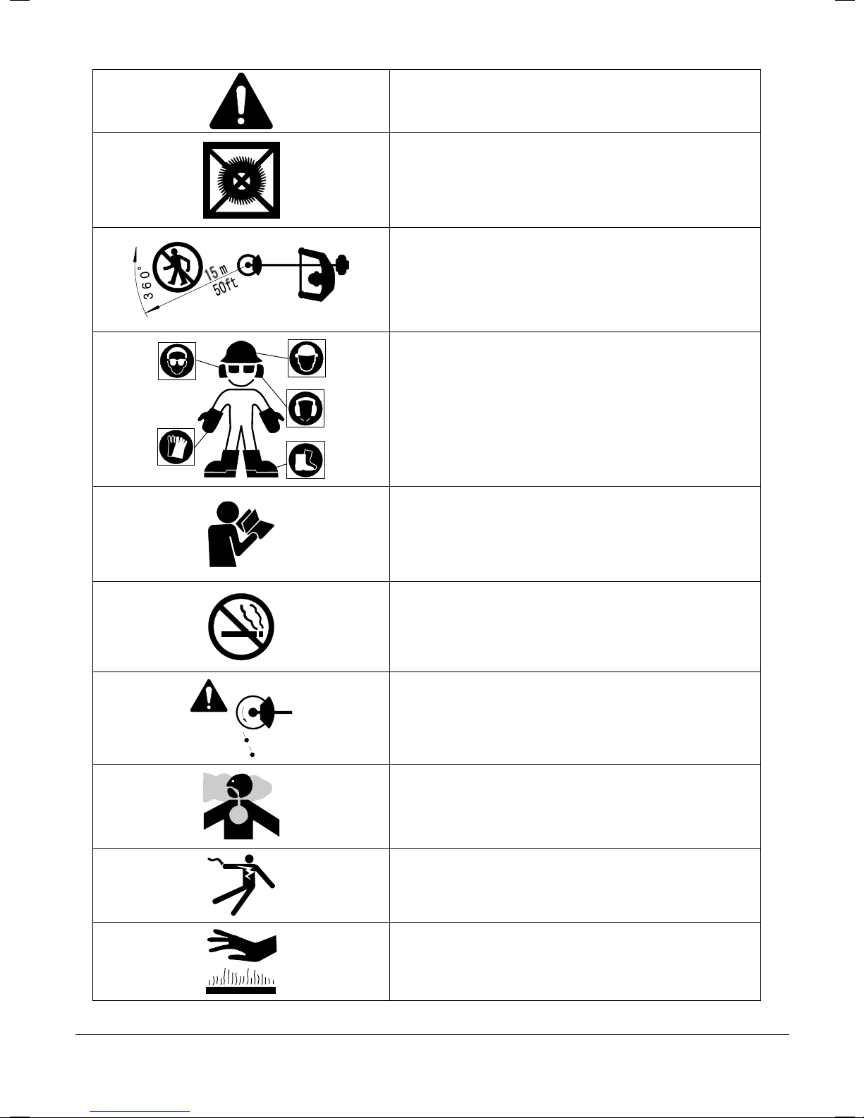
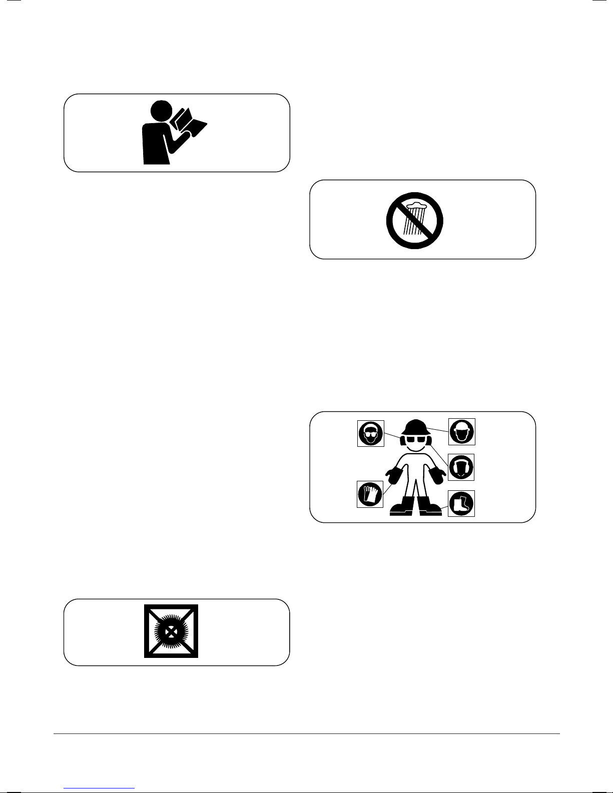
7. Safety Precautions
• Hold the machine securely with both hands. Grip the
control handle with your right hand; grip the other handle
with your left hand.
• To maintain a stable posture, adopt a stance wider than
shoulder width.
• Maintain a firm footing.
• Shut off the engine if abnormal noise or vibration occurs,
if an emergency occurs, or when putting down the
machine.
• If someone calls out or otherwise interrupts you while
working, always shut off the engine before turning around.
8. Special precautions when two or more
machines are in use
When two or more machines are in use simultaneously, it
is essential that all operators use extreme care to maintain
a safe distance from each other, constantly look around,
and always remain aware of presence of the other
operators to ensure safe operation.
9. Blade thrust
If a running blade hits a hard stationary object such as a
tree, rock, or wall, the cutting blade can kick back
violently in a phenomenon known as blade thrust. When
blade thrust occurs, the reaction can swing the cutting
blade violently in an unexpected direction, creating a high
risk of injury. To avoid blade thrust, strictly observe the
following:
• Before starting work, check for hard stationary objects
such as trees, rocks, or walls that can cause blade thrust.
Mark any hard stationary objects so that the operator can
avoid them.
• Do not use an excessively dull cutting blade.
10. Cutting pattern
MODEL: MT23HM/B
• The cutting attachments of the line trimmer rotate
clockwise. Cut a 1.5-meter arc from left to right. Within
this arc, maintain the cutting device at a consistent height
above the ground. Advance slowly and gradually,
beginning with the left foot.
• Cut brush with the arc on the cutting device. If the
arc on the rotating device hits a solid object, a cutting
device running at high speed will thrust toward the
operator, creating a very dangerous situation. (Fig.3-4)
MODEL: Other than MT23HM/B
• The cutting attachments of the brushcutter rotate
counterclockwise. Cut a 1.5-meter arc from right to left.
Within this arc, maintain the cutting blade at a consistent
height above the ground. Advance slowly and gradually,
beginning with the right foot.
• Cut brush with the arc on the cutting blade. If the
arc on the rotating blade hits a solid object, a cutting
blade running at high speed will thrust toward the
operator, creating a very dangerous situation. (Fig.3-5)
11. Abnormal noise and vibration
• If the machine suddenly exhibits abnormal noise or
vibration, immediately shut off the engine.
• Possible causes of sudden noise or vibration include
loose screws and damage to the cutting blade or other
components. Check the entire machine for any sign of a
problem.
• After the cause has been found, do not use the machine
until you have completed the repair.
Fig.3-4
Fig.3-3
Fig.3-5
Double handle
Loop handle

11
554282 - Masport Brushcutter OM - July 2010
- 7 -
[4] Fuel and Oil
DANGER
• Do not handle fuel near open fire (open flame, lit
cigarette, stove, etc.) or electrical spark (from
electrostatic discharge, welding spark, or switch or
battery short-circuit). Doing so can cause the fuel to
ignite, resulting in a fire.
• Do not refuel while the engine is running or while the
engine is still hot after shutting off the machine.
Allowing fuel to splash on a hot engine can result in a
fire.
• Refuel the machine outdoors or in a well-ventilated
location.
• After refueling, securely close the fuel cap and
thoroughly wipe off any spilled fuel. Spilled fuel can
ignite after the machine is running, leading to a fire.
NOTICE
Refer to the engine instruction manual for more details.
2-stroke engine
Fuel
When fueling a 2-stroke engine, use a fuel-oil mixture of
gasoline and 2-stroke engine oil.
• 2-stroke engine oil required
Use high-quality JASO FC class 2-stroke engine
oil.
NOTICE
Pour the engine oil into a mixing vessel. Add gasoline
and mix thoroughly.
CAUTION
• Do not mix the engine oil and fuel in the fuel tank of
the engine.
• Fuel-oil mixtures degrade over time. We recommend
that you prepare only the amount of the fuel-oil mixture
you will use in the short term. Do not use a fuel-oil
mixture that was prepared more than a week earlier. A
degraded fuel-oil mixture can damage the engine.
• Do not use a fuel-oil mixture containing an incorrect
proportion of engine oil. Doing so can cause an engine
malfunction or engine seizure.
Common fuel/oil ratios
4-stroke engine Models: MT27H & MT 36H
Fuel
For the 4-stroke engine, use regular lead-free gasoline.
CAUTION
Do not use a fuel-oil mixture prepared by blending oil
and gasoline. Doing so can result in hard starting, low
power output, and a clogged fuel system.
Oil
Use 4-stroke gasoline engine oil only.
Use 4-stroke oil for gasoline engines rated at API
service classification SJ or later (or equivalent).
NOTICE
• Before starting the engine, check the oil level.
Position the engine level with the ground. Confirm that
the oil level is to the base of the spout of the fill port. If
the level is too low, add oil.
• Change the oil if it appears dirty or discolored. (See
[8] Inspection and Maintenance 8. Changing the
engine oil.)
Fig.4-1
Fuel 2-stroke engine oil
50 1
50:1
2 %
80 mL4 ltr
402
201
101/2

12
554282 - Masport Brushcutter OM - July 2010
- 8 -
[5] Assembly
The standard tightening torques for the bolts, screws, and
nuts of the machine are listed below. If a specific
tightening torque value for a particular bolt, screw or nut
is not provided, apply a standard tightening torque
appropriate for the size of that bolt, screw or nut.
Size Torque (N・m)
M4 1.6
M5 3.1
M6 5.1
M8 12.2
M10 24.5
CAUTION
Do not overtighten, which can lead to broken parts.
[5-1] Mounting the cutting
attachment guard
WARNING
Never operate the brushcutter without the cutting
attachment guard properly installed.
The cutting attachment guard protects the operator
from thrown objects and prevents the cutting
attachment from contacting the operator. If the cutting
attachment is not properly installed, a thrown rock can
cause death or severe injury.
MODEL: MT23HM/B
1. Attach to extend miter of a guard (A) and to insert a
shaft case. (Fig.5-1)
2. Secure the guard by fully tightening screws (B) (M6 ×
45) and nuts (C) (M6).
MODEL: MT23HM
1. Sandwich the shaft tube between a protector(A) and a
protector holder(B). (Fig.5-2)
2. Secure these parts by tightening the bolts (C) (M5 ×
10).
MODEL: Other than MT23HM/B and MT23HM
●With cutting blade mounted
1. Place the cutting attachment guard (B) and plate (C)
against the cutting attachment guard holder (A). Align the
holes with their counterparts. (Fig.5-3)
2. Secure these parts by tightening the bolts (D) (M5 ×
16).
● With nylon trimmer mounted
CAUTION
The trimmer piece (F) is very sharp and can cause
injury. Wear heavy-duty gloves and handle the trimmer
piece (F) very carefully.
NOTICE
Before using the nylon trimmer, mount the skirt (E)
complete with the trimmer piece (F) onto the cutting
attachment guard (B). The purpose of the trimmer piece
(F) is to cut the nylon cord on the rotating nylon trimmer
to the correct length. This ensures the nylon trimmer can
rotate smoothly.
Fig.5-3
Fig.5-4
A
B
C
D
F
E
G
A
B
C
D
Fig.5-2
Fig.5-1
B
A
C
B
C
A
1. Attach the guard (A) to shaft as shown (Fig.5-1)
2. Secure the guard by fully tightening screw (B) (M6x45)
and nut (C) (M6).

13
554282 - Masport Brushcutter OM - July 2010
- 9 -
1. Place the cutting attachment guard (B) and plate (C)
against the cutting attachment guard holder (A). Align the
holes with their counterparts.
2. Secure these parts by tightening the bolts (D) (M5 ×
16).
3. Mount the trimmer piece (F) onto the skirt (E) with the
self-tapping screws (G) (#4 × 12).
[Tightening torque] 0.75 (N・m)
4. Firmly fit the skirt (E) into the slot in the cutting
attachment guard (B).
NOTICE
The slots provided in the trimmer piece (F) allow you to
finely adjust the height of the trimmer piece to the height
of the nylon cord.
To remove the skirt (E), insert a screwdriver into each of
the three slots in the cutting attachment guard (B), and
prize the skirt (E) out of the slot.
[5-2] Mounting the cutting
blade or nylon trimmer
NOTICE
• The cutting blade and nylon trimmer rotate
counterclockwise as viewed from the angle transmission
(A) side. (Fig.5-5)
• The clamping nut (F) of the angle transmission (A) is a
left-hand thread. (Tighten counterclockwise as viewed
from the clamping nut (F) side.)
● Locking the output shaft (A-2)
When loosening or tightening the clamping nut (F), lock
the output shaft (A-2) as described below.
1. Turn the blade retainer (B) until the hole (B-1) is
aligned with the hole (A-1) on the angle transmission.
2. Lock the blade retainer (B) by inserting the hex key
wrench (G) through the hole (A-1) in the angle
transmission and into the hole (B-1) in the blade retainer.
● Mounting the cutting blade
CAUTION
The cutting blade is very sharp and can cause injury.
Wear heavy-duty gloves when handling and mounting
the blade.
NOTICE
• Mount the cutting blade with the printed side against the
angle transmission (A) side.
• Correctly fit the hole in the center of the blade (C) onto
the protrusion on the blade retainer (B). If misaligned, the
blade (C) can work loose and generate abnormal noise or
vibration while in use.
1. Lock the output shaft (A-2). Turn the clamping nut (F)
clockwise and remove.
2. Mount the blade retainer (B), blade (C), blade retainer
(D), stabilizer (E) and clamping nut (F), in order, onto the
angle transmission (A). Confirm the correct orientation.
(Fig.5-6)
3. While locking the output shaft (A-2), turn the clamping
nut (F) counterclockwise until fully tightened. (Fig.5-7)
The sizes of the clamping nuts (F) are as follows:
MT36H, MT36K: M10
Others: M8
Fig.5-7
Fig.5-5
C
B
E
D
FFig.5-6
B
E
D
C
F
A
GA-1 A-2
B-1
Other than MODEL: MT23HM/B

14
554282 - Masport Brushcutter OM - July 2010
- 10 -
● Mounting the nylon trimmer
MODEL: MT23HM/B
1. Lock the output shaft (A-2). Turn the nylon trimmer
(H) clockwise until fully tightened. (Fig.5-8)
MODEL: MT23HM
NOTICE
• For the removal/setup method for the housing (H-1) of
the nylon trimmer, refer to the instruction manual for the
nylon trimmer.
• Do not use the stabilizer (E).
1. Lock the output shaft (A-2). Turn the clamping nut (F)
clockwise and remove.
2. Referring to the instruction manual for the nylon
trimmer, disassemble the nylon trimmer, separating the
housing (H-1) and the cord cassette (H-2).
3. Align the center hole of the housing (H-1) with the
protrusion on the blade retainer (B).
4. While locking the output shaft (A-2), turn the clamping
nut (F) counterclockwise until fully tightened.
5. Set the cord cassette (H-2) on the housing (H-1).
(Fig.5-9)
MODEL: Other than MT23HM/B and MT23HM
NOTICE
• For the removal/setup method for the housing (H-1) of
the nylon trimmer, refer to the instruction manual for the
nylon trimmer.
• Do not use the blade retainer (D) and the stabilizer (E).
1. Lock the output shaft (A-2). Turn the clamping nut (F)
clockwise and remove.
2. Referring to the instruction manual for the nylon
trimmer, disassemble the nylon trimmer, separating the
housing (H-1) and the cord cassette (H-2).
3. Align the center hole of the housing (H-1) with the
protrusion on the blade retainer (B).
4. While locking the output shaft (A-2), turn the clamping
nut (F) counterclockwise until fully tightened.
5. Set the cord cassette (H-2) on the housing (H-1).
(Fig.5-10)
Fig.5-10
Fig.5-9
Fig.5-8
H-1
H-2
F
A
D
E
A-2
B
A-2
H
H-1
F
A
E
A-2
B
H-2
G
G
G
B

15
554282 - Masport Brushcutter OM - July 2010
- 11 -
[5-3] Attaching the handle,
throttle linkage, and cord
● Attaching the handle
1. Loop handle
MODEL: MT23HM/B
1. Sandwich the shaft tube between the loop handle body
(A) and the handle holder (B). (Fig.5-11)
2. Secure the loop handle by fully tightening screws (C)
(M5 × 35) and nuts (D) (M5).
[Tightening torque] 1.5 (N・m)
MODEL: MT23HM
1. Attach to extend miter of a handle (A) and to insert a
pipe. (Fig.5-12)
2. Secure the loop handle by fully tightening screws (B)
(M5 × 30) and nuts (C) (M5).
[Tightening torque] 1.5 (N・m)
MODEL: MT27M, MT27K, MT27H
NOTICE
Attach the loop handle on the angle transmission side
relative to the position marker (F).
1. Using the position marker (F) on the shaft tube as a
guide, sandwich the shaft tube between the loop handle
body (A) and the handle holder (B). While doing so,
make sure handle holder (B) is oriented as indicated by
the arrow direction in the illustration. This arrangement is
intended to protect the operator from accidental contact
with the cutting attachment. (Fig.5-13)
2. Secure the loop handle by fully tightening screws (C)
(M5 × 30) and nuts (D) (M5).
[Tightening torque] 1.5 (N・m)
2. Double handle
MODEL: MT36K, MT36H
1. Slide the control handle (A) over handle (B). Secure by
tightening screw (J) (M5 × 30) and nut (K) (M5).
[Tightening torque] 1.5 (N・m)
2. Slide the handgrip (C) over handle (D). Secure by
tightening screw (L) (M5 × 30) and nut (M) (M5).
[Tightening torque] 1.5 (N・m)
3. Bring the inner end of handle (B) into contact with that
of handle (D). Fit both ends into the slot on the handle
holder (E-2).
4. Install the handle holder (E-1) and hand-tighten bolt
(N) (M6 × 20).
5. Mount handle holder (E-2) to handle holder (F). Hand-
tighten bolt (O) (M8 × 50).
6. Bring the inner ends of both handles into firm contact
in the middle of handle holder (E-1). Adjust the handle
angle.
7. Secure the handles by evenly tightening bolts (N) (M6
× 20) and (O) (M8 × 50).
8. Using clips (G) and (H), fix the throttle linkage and
cord assembly (I) to handle (B) and the shaft tube.
C
A
B
D
F
E
Fig.5-14
Fig.5-13
Fig.5-12
A
BC
E-1 D
F
G
H
I
K
J
L
M
O
N
E-2
Fig.5-11
B
C
A
B
C
D
A
1. Open the clamping faces of the handle (A) and insert
the shaft tube (Fig. 5-12).

16
554282 - Masport Brushcutter OM - July 2010
- 12 -
●Attaching the throttle linkage and cord
MODEL: Other than MT36K and MT36H
The throttle linkage and a code is already equipped.
MODEL: MT36K, MT36H
NOTICE
Refer to the engine instruction manual for more details.
1. Referring to the engine instruction manual, remove the
air cleaner cover (A).
2. Loosen the lock nut (C) on the throttle linkage (B).
3. Fit the leading end (E) of the throttle linkage into the
slot of the leading end mount (F) of the carburetor. Check
for the correct orientation of the leading end mount (F).
(Fig.5-16)
4. Fit the throttle linkage into the stay (G), adjust the play
at the leading end of throttle linkage (E) with adjustment
nut (D), and secure the adjustment with the lock nut (C).
NOTICE
Make sure that the play at the leading end of throttle
linkage (E) is within the range of 1 to 2 mm. (Fig.5-16)
5. Using the screw & washer assembly (I) (M5 × 10),
connect the engine cord (H) to the engine (MT36H only).
6. Connect the cord (J) from the control handle to the
engine cord.
7. Mount the air cleaner cover (A).
[6] Starting and Stopping the
Engine
DANGER
• Start up the engine only when no open flame is
located near the machine.
• Start the engine at a location at least 3 meters away
from the refueling area or the fuel container. Fuel is
highly inflammable, and a fire can lead to death or
severe injury.
WARNING
• In some cases the cutting blade or nylon trimmer can
suddenly begin rotating when the engine is started.
Provide a safe distance around the cutting blade or
nylon trimmer before starting the engine.
• Make sure that no bystanders are within 15 meters
before starting the engine.
• Place the machine on flat solid ground before starting
the engine.
• Make sure the cutting blade or nylon trimmer is not in
contact with the ground or any other object.
NOTICE
Refer to the engine instruction manual for more details.
MODEL: MT23HM/B, MT23HM
A
A
C
1~2 m
m
H
J
JB
D
B
E
F
G
E
F
E
G
F
C
D
I
Fi
g
.5-15
MT36H
MT36K
Fi
g
.5-16
MT36K
MT36H
Fig.6-3
Fig.6-1
Fi
g
.6-4
A
C
B
Fig.6-2
Re-assemble the air cleaner cover (A).

17
554282 - Masport Brushcutter OM - July 2010
- 13 -
● Starting the engine
NOTICE
To prevent the throttle trigger (C) from being accidentally
actuated and starting the cutting blade, a throttle trigger
lockout (B) is provided on the throttle trigger (C). The
throttle trigger (C) can be actuated only when the throttle
trigger lockout (B) is pushed downward.
1. Set the stop switch (A) to the middle position. (Fig.6-3)
2. Fully squeeze both the throttle trigger lockout (B) and
the throttle trigger (C) at the same time. (Fig.6-1)
3. Set the stop switch (A) to the START position (Fig 6-2),
release both the throttle trigger lockout (B) and throttle
trigger (C).
The throttle will be locked in the middle opening position
(“starting throttle lock”), which enables you to start the
engine easily.
4. Repeatedly push the primer (D) until fuel starts to flow
inside the clear fuel return tube (G). (Fig.6-5)
NOTICE
If the primer (D) is pushed too many times, any excess
fuel will return to the fuel tank. Push the primer a
sufficient number of times to prime the engine. The
engine will fail to start if priming is insufficient.
5. When the engine is cold, set the choke lever (E) to the
START position. When the engine is warm, there is no
need to actuate the choke lever (E). (Fig.6-5)
6. Hold the machine steady and pull hard on the recoil
starter (F) to start the engine. It may be necessary to pull
on the starter repeatedly.
7. If you have set the choke lever (E) to the START
position in step 5 above, return the lever to its original
position.
8. Squeeze throttle trigger (C) again and release quickly.
This releases the starting throttle lock and causes the
engine to idle.
9. When the engine is cold, allow it to idle for about three
minutes to warm it up.
● Shutting off the engine
1. Release the throttle trigger (C).
2. Slide the stop switch (A) to the STOP position. (Fig.6-
4)
WARNING
Even after the engine has been shut off, the rotating
section (cutting blade or nylon trimmer) will continue
to rotate for a while. Hold the brushcutter steady until
all moving parts have stopped completely. The cutting
blade is very sharp, and can cause death or severe
injury.
MODEL: MT27M, MT27K, MT27H
● Starting the engine
NOTICE
To prevent the throttle trigger (C) from being accidentally
actuated and starting the cutting blade, a throttle trigger
lockout (B) is provided on the throttle trigger (C). The
throttle trigger (C) can be actuated only when the throttle
trigger lockout (B) is pushed downward.
•MODEL: MT27M, MT27H
1. Set the stop switch (A) to the START position.(Fig.6-7)
2. Fully squeeze both the throttle trigger lockout (B) and
the throttle trigger (C) at the same time. (Fig.6-6)
3. While pressing knob (I), release both the throttle
trigger lockout (B) and throttle trigger (C).
The throttle will be locked in the middle opening position
(“starting throttle lock”), which enables you to start the
engine easily.
4. Repeatedly push the primer (D) until fuel starts to flow
inside the clear fuel return tube (G). (Fig.6-5)
NOTICE
If the primer (D) is pushed too many times, any excess
fuel will return to the fuel tank. Push the primer a
sufficient number of times to prime the engine. The
engine will fail to start if priming is insufficient.
5. When the engine is cold, set the choke lever (E) to the
START position. When the engine is warm, there is no
need to actuate the choke lever (E). (Fig.6-5)
6. Hold the machine steady and pull hard on the recoil
starter (F) to start the engine. It may be necessary to pull
on the starter repeatedly.
Fig.6-7
Fig.6-6
Fi
g
.6-8
Fig.6-5
START
G
D
EF
H
A
C
IB
MODEL: MT27M, MT27H ONLY

18
554282 - Masport Brushcutter OM - July 2010
- 14 -
7. If you have set the choke lever (E) to the START
position in step 5 above, return the lever to its original
position.
8. Squeeze throttle trigger (C) again and release quickly.
This releases the starting throttle lock and causes the
engine to idle.
9. When the engine is cold, allow it to idle for about three
minutes to warm it up.
•MODEL: MT27K
NOTICE
Unlike the other MODEL, MT27K is starting throttle
lock cannot be manipulated.
NOTICE
Move the choke lever (K) to the START position and
squeeze the throttle trigger (C). The choke lever (K) will
automatically return to the original position.
1. Set the stop switch (A) to the START position. (Fig.6-
7)
2. Repeatedly push the primer (J) until fuel starts to flow
inside the clear fuel return tube (M). (Fig.6-9)
NOTICE
If the primer (J) is pushed too many times, any excess
fuel will return to the fuel tank. Push the primer (J) a
sufficient number of times to prime the engine. The
engine will fail to start if priming is insufficient.
3. When the engine is cold, set the choke lever (K) to the
START position. When the engine is warm, there is no
need to actuate the choke lever (K). (Fig.6-9)
4. Hold the machine steady and pull hard on the recoil
starter (L) to start the engine. It may be necessary to pull
on the starter repeatedly. (Fig.6-9)
5. If you have set the choke lever (K) to the START
position in step 3 above, squeeze the throttle trigger (C)
quickly to release the choke.
6. When the engine is cold, allow it to idle for about three
minutes to warm it up.
● Shutting off the engine
1. Release the throttle trigger (C).
2. Slide the stop switch (A) to the STOP position. (Fig.6-
8)
WARNING
Even after the engine has been shut off, the rotating
section (cutting blade or nylon trimmer) will continue
to rotate for a while. Hold the brushcutter steady until
all moving parts have stopped completely. The cutting
blade is very sharp, and can cause death or severe
injury.
● Adjusting engine speed
Knob (H) on the control handle is a throttle limiter.
(Fig.6-6) Turn knob (H) clockwise to reduce the engine
speed reached when the throttle trigger (C) is squeezed.
Turn knob (H) counterclockwise to increase the engine
speed reached when the throttle trigger (C) is squeezed.
Adjust the position of knob (H) to match the work
conditions.
MODEL: MT36K, MT36H
Fig.6-10
Fig.6-11
Fig.6-12
Fig.6-13
N
P
O
Fig.6-9
J
M
KL
START
Unlike the other MODELS, MT27K starting throttle
lock cannot be manipulated.
MODEL: MT27K ONLY

19
554282 - Masport Brushcutter OM - July 2010
- 15 -
● Starting the engine
NOTICE
To prevent the throttle trigger (O) from being accidentally
actuated and starting the cutting blade, a throttle trigger
lockout (P) is provided on the throttle trigger (O). The
throttle trigger (O) can be actuated only when the throttle
trigger lockout (P) is pushed downward.
•MODEL: MT36H
1. Fully squeeze both the throttle trigger lockout (P) and
the throttle trigger (O) at the same time. (Fig.6-10)
2. While sliding stop switch (N) to START, release both
the throttle trigger lockout (P) and the throttle trigger (O)
(Fig.6-11). The throttle will be locked in the middle
opening position (“starting throttle lock”), which enables
you to start the engine easily.
3. Repeatedly push the primer until fuel starts to flow
inside the clear fuel return tube.
NOTICE
If the primer is pushed too many times, any excess fuel
will return to the fuel tank. Push the primer a sufficient
number of times to prime the engine. The engine will
fail to start if priming is insufficient.
4. When the engine is cold, set the choke lever to the
START position. When the engine is warm, there is no
need to actuate the choke lever.
5. Hold the machine steady and pull hard on the recoil
starter to start the engine. It may be necessary to pull on
the starter repeatedly.
6. If you have set the choke lever to the START position
in step 4 above, return the lever to its original position.
7. Squeeze throttle trigger (O) again and release quickly.
This releases the starting throttle lock and causes the
engine to idle. (Fig.6-12)
8. When the engine is cold, allow it to idle for about three
minutes to warm it up.
•MODEL: MT36K
NOTICE
Unlike the MT36H, MT36K is starting throttle lock
cannot be manipulated.
NOTICE
Move the choke lever (K) to the START position and
squeeze the throttle trigger (O). The choke lever (K) will
automatically return to the original position. (Fig.6-9)
1. Push the stop switch (N) to the START position.
(Fig.6-9)
2. Repeatedly push the primer (J) until fuel starts to flow
inside the clear fuel return tube (M). (Fig.6-9)
NOTICE
If the primer (J) is pushed too many times, any excess
fuel will return to the fuel tank. Push the primer (J) a
sufficient number of times to prime the engine. The
engine will fail to start if priming is insufficient.
3. When the engine is cold, set the choke lever (K) to the
START position. When the engine is warm, there is no
need to actuate the choke lever (K). (Fig.6-9)
4. Hold the machine steady and pull hard on the recoil
starter (L) to start the engine. It may be necessary to pull
on the starter repeatedly. (Fig.6-9)
5. If you have set the choke lever (K) to the START
position in step 3 above, squeeze the throttle trigger (O)
quickly to release the choke.
6. When the engine is cold, allow it to idle for about three
minutes to warm it up.
● Shutting off the engine
1. Release the throttle trigger (O).
2. Slide the stop switch (N) to the STOP position.(Fig.6-
13)
WARNING
Even after the engine has been shut off, the rotating
section (cutting blade or nylon trimmer) will continue
to rotate for a while. Hold the brushcutter steady until
all moving parts have stopped completely. The cutting
blade is very sharp, and can cause death or severe
injury.
● Adjusting engine speed
Knob (Q) on the control handle is a throttle limiter. Turn
knob (Q) clockwise to reduce the engine speed reached
when the throttle trigger (O) is squeezed. Turn knob (Q)
counterclockwise to increase the engine speed reached
when the throttle trigger (O) is squeezed. Adjust the
position of knob (Q) to match the work conditions.
NOTICE
If knob (Q) is overtightened (in the clockwise direction),
it will be impossible to keep stop switch (N) in the
START position.
Fig.6-14
Q
MODEL: MT36H ONLY
MODEL: MT36K ONLY

20
554282 - Masport Brushcutter OM - July 2010
- 16 -
[7] Wearing the Harness
NOTICE
The harness has a quick-release mechanism that allows
you to immediately release the machine from the harness
in an emergency.
● Attaching the side hook
NOTICE
If side hook (D) has disengaged from hook (B), engage it.
1. Insert hook (B) into side hook (D).
2. While holding hook (B) and side hook (D) in place,
insert stopper (C) into the hole on hook (B). (Fig.7-1)
● Adjusting the harness
1.As shown in the diagram, adjust the harness (A) so that
hip pad (E) is against your right hip. (Fig.7-2)
2.Before starting to work, attach the side hook (D) to the
suspension point (F) on the shaft tube. (Fig.7-3)
● Recommended working position
CAUTION
If releasing both hands from the handle, use extreme
care. Suddenly releasing the handle can cause the
cutting blade or nylon trimmer to kick, possibly
resulting in injury.
• Before starting the engine, put on the harness correctly,
attach the brushcutter to the harness, and stand in the
correct brushcutter holding stance.
• Ensure the cutting blade is 100 mm to 300 mm above
the ground before releasing both hands from the handle.
• Ensure the nylon trimmer is 0 mm to 300 mm above the
ground before releasing both hands from the handle.
(Fig.7-4)
• See “Adjusting the holding position” for details.
NOTICE
After installing a new cutting attachment, confirm the
correct holding position and make any necessary
adjustments.
● Adjusting the holding position
• To adjust the holding position, simply change the length
of the harness belt and the location of the suspension
point.
• Use the following procedure to adjust the suspension
point.
D
A
C
B
Fig.7-1
Fig.7-2
A
A
E
E
Fig.7-3
F
D
About 200 mm
Fig.7-4
This manual suits for next models
6
Table of contents
Other Masport Brush Cutter manuals