1
MASter of PROduction
Read this instruction manual carefully before use.
ch. E21~E58
U144LK2
U204LK2
Instruction Manual
For Horizontal
Polarization
75Ω
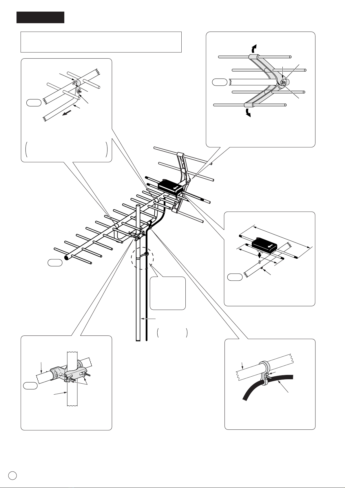
Beam Dipole
MASPRO's original beam dipole with built-in phase
shifter provides excellent gain and VSWR over the wide
band.
Corner Reflector
MASPRO UHF antenna with corner reflector reduces
double images, and make clear pictures.
Aluminum Double Boom
Double structured aluminum boom and boom support
are light yet sturdy.
Corner
Reflector
Beam Dipole
Boom
Boom
Support
NOTE Skills and experience are required to install antennas on roofs or other elevated
locations. Make sure to consult your dealer concerning installation.
Antenna Installation Precautions
¡Be very careful to install antenna at the safest spot possible, so
that parts of the antenna will not cause injury or property damage
if they fall.
¡To prevent electric shock accidents, install the antenna as far
away as possible from wires (powerlines, high voltage wires,
telephone lines) so that it will not come into contact with the wires
even if it falls.
¡Never attempt installation on rainy or windy days. Be extremely
careful also when working under a scorching sun in summer, as
the roof can become very hot.
¡Take necessary safety measures before installing antenna, e.g.
binding the antenna, mounting brackets, and tools to prevent
them from dropping.
¡Working at elevated locations is extremely dangerous. Take all
safety measures possible before installation. When you are on the
roof, you may experience vertigo or experience an exaggerated
sense of height, your feet may become shaky and your footing
unstable. Take special care to avoid slipping.
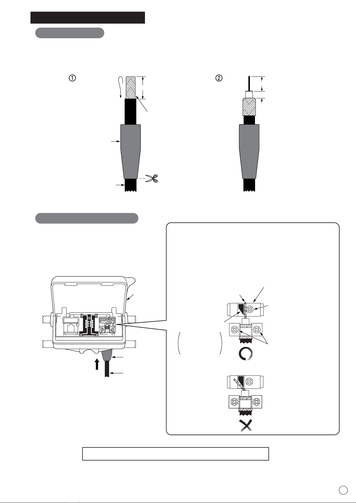
¡Make sure to remove TV and/or Tuner AC plugs from AC wall
outlets when you connect 75Ωcoaxial cable from TV and/or Tuner.
If plugs remain in outlets, electric shock may occur.
¡Do not install the antenna and guy wire by yourself. Make sure that
someone, or preferably two or more people, are present to assist
you.
¡Reception level of the TV signals may differ depending on where
you install the TV antenna. During installation, try to adjust the
position, height and direction of the antenna for optimum reception.
¡After a typhoon or heavy snow, check the antenna, mounting
brackets, mast, roof mount, and guy wires for any signs of trouble
or loosened bolts and nuts. Replace damaged or bent antenna with
a new one. If you neglect damaged antenna or leave them without
proper maintenance, parts of the antenna and mounting brackets
may become damaged and drop, causing physical injury or
property damage.
¡Be careful not to use a rusty or corroded antenna and mounting
bracket. Weak or damaged equipment may loosen and drop,
resulting in physical injury or property damage.
UHF ANTENNA
HIGH PERFORMANCE
(For Home Use)
U144LK2
(14elements)
U204LK2
(20elements)