Mastech MS8361D User manual

MS8361D
CAT III

Contents
1. Safety standards
1.1 FCC Statement
1.2 Using the meter
1.3 Safety standards
1.4 Maintenance
2. Description
2.1 Part name
2.2 Buttons/ Input jack description
2.3 Auto power off function
2.4 LCD Display
3. Technical specifications
3.1 General specifications
3.2 Technical indicators
3.2.1 Dc voltage
3.2.2 Ac voltage
3.2.3 Resistance
3.2.4 Diode test
3.2.5 Continuity
3.2.6 DC current
3.2.7 AC current
3.2.8 hFE transistor gain
3.2.9 Capactance
3.2.10 Frequency
3.2.10.1 In V mode
3.2.10.2 In ηA,mA,A mode
3.2.10.3 In Hz mode
3.2.10.4 Duty ratio
4. Operating instructions
4.1 AC/DC Voltage measurement
4.2 AC/DC Current measurement
4.3 Resistance measurement
4.4 Continuity measurement
1
1
2
3
4
5
5
7
8
8
9
9
10
10
10
11
11
11
12
12
13
13
13
13
14
14
15
16
16
16
17
18
4.5 Diode test
4.6 Capacitance measurement
4.7 Transistor measurement
4.8 Frequency measurement
4.9 Non-contact voltage(NCV) measurement
4.10 Wireless operation
5. Maintenance
5.1 General Maintenance
5.2 Replacing the battery
5.3 Replacing the fuse
5.4 Replacing the Probe
6. Accessories
18
19
19
20
20
21
21
21
22
22
22
23
Contents

1. Safety standards
The multimeter meets the following safety standards:
EN/UL/CSASTD C22.2 NO. 61010-1,61010-2-030,
61010-2-033for electronic testing instruments. This meter
meets CAT III 600V installations and a pollution degree of 2.
• The protection provided by the meter can only be ensured if all
safety procedures are strictly followed.
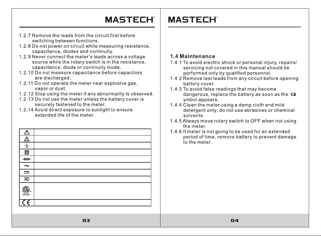
• The safety symbols on the meter are to advise of potential
dangerous situations. Caution is required when measuring
close to the meter’s safety limits.
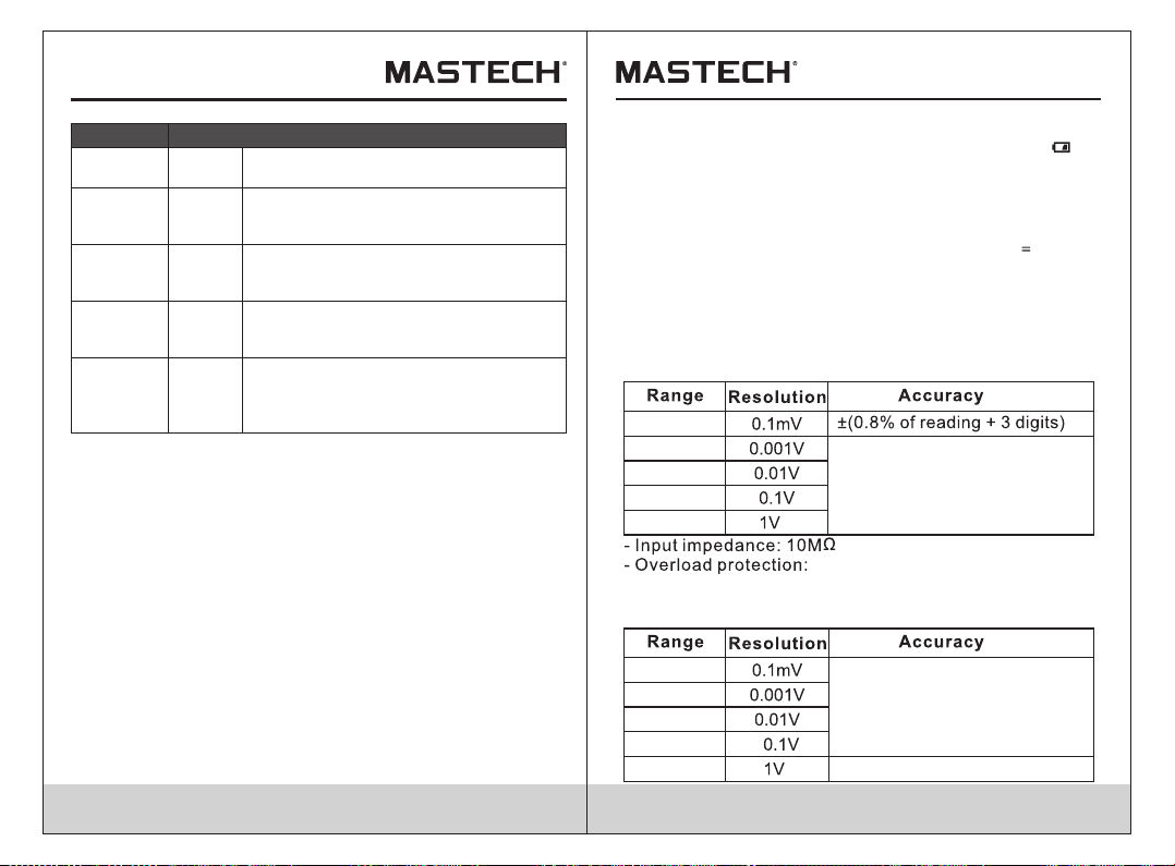
• Never exceed the protection limit values indicated in the
specifications for each range of measurement.
The special attention should be paid when using the meter
because the improper usage may cause electric shock and
damage the meter. The safety measures in common safety
regulations and operating instruction should be complied
with when using. In order to make fully use of its functions
and ensure safe operations please comply with the usage in
this section carefully.
WARNING
1.1 FCC Statement
This device complies with part 15 of the FCC Rules.
Operation is subject to the following two conditions: (1) This
device may not cause harmful interference, and (2) this
device must accept any interference received, including
interference that may cause undesired operation.
This equipment has been tested and found to comply with the
limits for a Class B digital device, pursuant to part 15 of the
FCC Rules. These limits are designed to provide reasonable
protection against harmful interference in a residential
installation. This equipment generates, uses and can radiate
radio frequency energy and, if not installed and used in
accordance with the instructions, may cause harmful
interference to radio communications. However, there is no
guarantee that interference will not occur in a particular
installation. If this equipment does cause harmful interference
to radio or television reception, which can be determined by
turning the equipment off and on, the user is encouraged
to try to correct the interference by one or more of the
following measures:
- Reorient or relocate the receiving antenna.
- Increase the separation between the equipment and receiver.
- Connect the equipment into an outlet on a circuit different
from that to which the receiver is connected.
- Consult the dealer or an experienced radio/TV technician
for help.
Caution:
Any changes or modifications not expressly approved by the
party responsible for compliance could void the user's
authority to operate the equipment.

1.3 Safety standards
AC & DC (Both direct and Alternating Current)
Important safety information.
High voltage with danger.
Ground.
Double Insulation (Class II safety equipment).
Fuse must be replaced as per the specification herein.
AC (Alternating Current)
DC (Direct Current)
Conforms to UL STD. 61010-1, 61010-2-030,
61010-2-033; Certified to CSA STD C22.2 NO.
61010-1, 61010-2-030,61010-2-033
Complies with European (EU) safety standards
CAT III: MEASUREMENT CATEGORY III is applicable to
test and measuring circuits connected to the distribution
part of the building's low-voltage MAINS installation.

No. Description No. Description
1
2
3
4
5
6
7
LCD display
Hold/BKL
Frequency/Duty-cycle
Wireless
Rotary switch
Input jack (V,R,D,F,C)
Common jack
8
9
10
11
12
13
14
Input jack (hFE,μA,mA)
Input jack (10A)
Function button
Range button
Relative button
Voltage alert light
Voltage alert area
-The multimeter is a portable, hand-held yet professional
meter that features true RMS measurement display, AC/
DC current, AC/DC voltage, Frequency, Capacitance,
Resistance, Communication, non-contact voltage tests
and hEF tests. This meter is easy to use even with one
hand, suitable for professional user or amateurs, and
ideal for school or home use.
- Both auto and manual range.
-Display hold.
-True RMS for AC voltage/ current measurements.
-Relative measurement.
-Automatic Power OFF.

FUNC button:
• Press “FUNC” to switch between AC/DC or between
function in a rotary switch position.
HOLD button:
• Press “HOLD” to keep the current reading on screen.
“H” symbol will appear on the display.
• Press “HOLD” again to release th hold.
button:
• Press “ ” to turn on the backlight. the backlight will
turn off automatically after 15 seconds
RANGE button:
• Press “RANGE”to switch to manual range.Each press
of the button will switch to the next highest range, until
reaching the highest range where it will switch to the
lowest range.
• Hold “RANGE” to return to auto range.
button:
• With the rotary switch in any position other than OFF,
press to enable the Wireless communication function
of the meter. Open the app (iOS or Android) on the
mobile device to be used and search for the multimeter
and establish a connection. Once connected, the app
will mirror the display of the meter and show any
measurement being performed. Press again to
disconnect the meter from the mobile device.
Hz/DUTY button:
• Press “Hz/DUTY” to start the frequency counter.
• Press “Hz/DUTY” again to enter duty-cycle mode.
• Press “Hz/DUTY” again to exit the frequency counter
mode.
REL button:
• Press “REL” to enter and exit the relative measurement
mode.
2.3 Auto power off function
• After 15 minutes of non-use the meter will automatica-
lly turn itself off.
• To turn the meter back on, press “FUNC”.
• To deactivate the auto power off function, hold down
“FUNC” when turning on the meter. will no longer be
displayed.
2.2 Buttons/Input jack description
2.4 LCD Display
6 7 8 9 10 11 12
13
14
15
5
4
3
2
1
No. Description
1
2
3
4
5
6
7
8
DC (direct current)
AC (alternating current)
Polarity indicator
Wireless indicator
Auto power off indicator
Auto-range
Transistor test mode
Relative measurement
No. Description
9
10
11
12
13
14
15
16
Data hold
True root mean square
Diode measurement
Continuity buzzer
Low battery indicator
Unsafe voltage warning
Measurement units
Main display
16
07 0 8

Symbol Description
V,mV V:
mV:
Volts. The unit of voltage.
Millivolt. 1x10 or 0.001 volts.
A,mA,µA
A:
mA:
µA:
Amperes (amps). The unit of current.
Milliamp. 1x10 or 0.001 amperes.
Microamp. 1x10 or 0.00001 amperes.
Ω Ω Ω,K ,M
Ω:
kΩ:
MΩ:
Ohm. The unit of resistance.
Kilohm. 1x10 or 1000 ohms.
Megohm. 1x10 or 1,000,000 ohms.
Hz,KHz,MHz
Hz:
KHz:
MHz:
Hertz. The unit of frequency.
Kilohertz. 1x10 or 1000 hertz.
Milohertz. 1x10 or 1,000,000 hertz.
Hz,KHz,MHz
F:
mF:
μF:
nF:
Farad. The unit of capacitance.
Millifarad. 1x10 or 0.001 farads.
Microfarad. 1x10 or 0.000001 farads.
Nanofarad. 1x10 or 0.000000001 farads.
-3
-3
-6
3
6
3
6
-3
-6
-9
3. Technical specifications
3.1 General specifications
Safety Rating: CAT III 600V, pollution degree of 2
Operating Altitude: <2000m
Operating Temperature/Humidity: 0~40℃, <80% RH
Storage Temperature/Humidity: -10~60℃, <70% RH,
remove battery
Max. Input between terminals and earth ground: 600V DC
or AC True-RMS
Fuse Protection: A/mA ranges: FF 400mA H 1000V
10A range: FF 10A H 600V
Display: 3³⁄4 digit LCD display
Overload Indication: Display shows “OL”
Low Battery Indication: When battery voltage drops below
normal operating voltage, “ ” is
shown on the display
Polarity Indication: Display automatically displays “-”
Power Supply: DC 9V (NEDA 1604, 6F22 or 006P)
Wireless Communication Distance:
Indoor/Outdoor: <10m
Supported App OS: iOS: 7.0 and above
Android: 4.3 and above
Size(LxWxH): Approx. 92x188x50mm
Weight: Approx. 432g
Accurancy: ±( % reading + digits ) at 18℃~28℃ with a
relative humidity of <80%; guaranteed for a period of
one year.
3.2 Technical indicators
3.2.1 Dc voltage
400mV
4.0V
40V
400V
600V DC or AC True-RMS.
600V
±( 1% of reading + 5 digits )
- Max. input voltage: 600V DC or AC True-RMS.
400mV
4.0V
40V
400V
3.2.2 Ac voltage
±( 1.0% of reading + 8 digits )
09 1 0
600V ±( 1.2% of reading + 8 digits )

- Input impedance: 10M
- Max. input voltage: 600V DC or AC True-RMS.
- Frequency reponse: 40~400Hz
- Response: True-RMS
3.2.3 Resistance
400Ω
4KΩ
40KΩ
400KΩ
4MΩ
40MΩ
±( 0.8% of reading + 3 digits )
- Overload protection: 600 DC or AC True-RMS
3.2.4 Diode test
1mV2.7V
Displays shows forward
voltage drop
- Overload protection: 600V DC or AC True-RMS
3.2.5 Continuity
Open circuit
voltage~1 V
- Overload protection: 600V DC or AC True-RMS
3.2.6 DC current
400μA
4000μA
40mA
400mA
10A
0.01mA
0.1mA
±( 1.0% of reading + 10 digits )
- Overload protection:
mA jack: FF 400mA H 1000V
10A jack: FF 10A H 600V
- Max input current:
mA jack: 400mA
10A jack: 10A
3.2.7 AC current
400μA
4000μA
40mA
400mA
10A
0.01mA
0.1mA
±( 1.5% of reading + 5 digits )
±( 3.0% of reading + 5 digits )
- Overload protection:
mA jack: FF 400mA H 1000V
10A jack: FF 10A H 600V
- Frequency response: 40~400Hz, true RMS response
- Max input current: mA jack: 400mA DC or AC rms
10A jack: 10A DC or AC rms
- When measuring current exceeding 2A, do not measure
for longer than 2 minutes continuously. Wait 10 minutes
11 1 2
to continue measurement.

3.2.8 hFE transistor gain
hFE
- Base current: approx. 5µA
- Vce: approx. 1.6V
- Protection: FF 400mA H 1000V
Description
Displays approx. hFE transistor
gain (0-1000)
3.2.9 Capactance
9.999nF
99.99nF
999.9nF
9.999μF
99.99μF
999.9μF
9.999mF
99.99mF
±( 5.0% of reading + 5 digits )
±( 4.0% of reading + 5 digits )
- Overload protection: 600 DC or AC True-RMS
3.2.10 Frequency
3.2.10.1 In V mode
- Input voltage range: >3V AC (True-RMS)
( higher input voltage at higher frequency )
- Input impedance: 10MΩ
- Max.input voltage: 600V AC (True-RMS)
=
3.2.10.2 In μA,mA,A mode
99.99Hz
999.9Hz
>1KHz
-Input current range:
μA range:> 100μA AC(True-RMS)
mA range: > 10mA AC (True-RMS)
A range: > 5A AC(True-RMS)
( higher input current at higher frequency )
- Max.input current:
μA range: 400mA AC(True-RMS)
mA range: 400mA AC(True-RMS)
A range: 10 A AC(True-RMS)
=
=
=
99.99Hz
999.9Hz
9.999KHz
>10KHz
3.2.10.3 In Hz mode
9.999Hz
99.99Hz
9.999KHz
999.9Hz
99.99KHz
999.9KHz
0.001Hz
0.1kHz
±( 0.5% of reading + 3 digits )
13 1 4
9.999MHz 0.001mHz

- Input voltage range: >2V AC (True-RMS)
( higher input voltage at higher frequency )
- Max.input voltage: 600V AC (True-RMS)
=
3.2.10.4 Duty ratio
0.1%-99.9%
±3.0%
• By μA, mA, A range:
- Input current range:
μA range: > 100μA AC (True-RMS)
mA range: > 10mA AC (True-RMS)
A range: > 5A AC (True-RMS)
( higher input current at higher frequency )
- Max.input current:
μA range: 400mA AC (True-RMS)
mA range: 400mA AC (True-RMS)
A range: 10 A AC (True-RMS)
• By V range:
- Input voltage range: > 3V AC (True-RMS)
( higher input voltage at higher frequency )
=
=
=
=
- Input impedance: 10MΩ
- Max.input voltage: 600V AC (True-RMS)
4. Operating instructions
4.1 AC/DC Voltage measurement
• Set the rotary switch to the AC or DC voltage position.
• Connect the red test lead to the input jack and the
black lead to the COM jack.
• Connect the leads to the circuit under test and read the
measurement on the display. Observe polarity for DC
measurement. In manual mode, if “OL” is display it
means the measurement has exceeded the current
range. Increase the selected range and measure again.
WARNING
Do not measure voltages higher than 600V DC or AC rms to
prevent damage to the meter or personal injury.
WARNING
Never measure open-circuit voltages exceeding 600V between
the input terminals and ground to prevent injury or damage to
the meter.
4.2 AC/DC Current measurement
• Turn off power to the circuit. Allow all capacitors to
discharge.
• Set the rotary switch to the appropriate AC/DC current
voltage.
• Press “FUNC” to switch between AC and DC current.
• Depending on the current to be measured, connect the
red test lead to either the input or 10A jack and the black
lead to the COM jack.
• Break the circuit and connect the leads in series with
the circuit (black lead on the lower voltage side).
• By Hz range:
- Input voltage range: >2V AC (True-RMS)
( higher input voltage at higher frequency )
- Max.input voltage: 600V AC (True-RMS)
=
15 1 6

• Turn circuit power on and read the measurement on the
display, it means the measurement has exceeded the
current range. Move the rotary switch to a higher range.
Note:
- Check fuses before making current measurements. Make
sure to use correct input jacks to prevent damage to the
meter.
4.3 Resistance measurement
• Turn off the power to the circuit. Allow all capacitors to
discharge.
• Set the rotary switch to the multi-function position. The
default function is resistance.
• Connect the red test lead to the input jack and the black
lead to the COM jack.
• Connect the leads to the circuit under test and read the
measurement on the display.
Tips for measuring resistance:
• In-circuit resistance is usually different from a resistors
rating due to the factthat the meter’s test current flows in
parallel with the circuit.
• For increased accuracy when measuring low resistance,
short the test leads, record the test displayed, then
connect the leads to the circuit and subtract the shorted
value from the circuit measurement.
• When the leads are disconnected from the circuit under
test, “OL” will be displayed on the screen.
WARNING
To prevent injury or damage to the meter, turn off power to
circuitand discharge all capacitors fully before making
resistance measurements.
4.4 Continuity measurement
• Turn off the power to the circuit. Allow all capacitors to
discharge.
• Set the rotary switch to the multi-function position.
Press “FUNC” twice to enter continuity mode.
• Connect the red test lead to the input jack and the black
lead to the COM jack.
• Connect the leads to the circuit under test. If the
measured resistance is less than 50Ω,the buzzer will
sound.
WARNING
To prevent injury or damage to the meter, turn off power to
circuit and discharge all capacitors fully before making
continuity measurements.
4.5 Diode test
• Turn off the power to the circuit. Allow all capacitors to
discharge.
• Set the rotary switch to the multi-function position.
Press “FUNC” once to enter diode mode.
• Connect the red test lead to the input jack and the black
lead to the COM jack.
• Connect the red test lead to the anode (+) and the black
lead to the cathode (-) of the diode and read the meas-
urement on the display.
The meter will display “OL” if the connection is reserved.
WARNING
To prevent injury or damage to the meter, turn off power to
circuit and discharge all capacitors fully before making diode
measurements.
17 1 8

4.6 Capacitance measurement
• Turn off the power to the circuit. Allow all capacitors to
discharge.
• Set the rotary switch to the multi-function position. Press
“FUNC” three times to ativate capacitance test.
• Connect the black and red test leads to the COM and
terminals respectively (or you can measure the capacitan-
ce by using the special multi-function socket).
• Connect the test leads to the capacitor being measured
and read the displayed value.
Some tips for measuring capacitance:
• The meter may take a few seconds to stabilize reading.
This is normal for for high capacitance measuring.
• To improve the accurancy of measurements less than
10nF, subtract the residual capacitance of the meter and
leads.
WARNING
To avoid eletrical shock and/or damage to the instrument,
disconnect circuit power and discharge all high-voltage
capacitors before measuring capacitance. Use the DC voltage
function to confirm that the capacitor is discharged.
4.7 Transistor measurement
• Set the rotary switch to hFE range.
• Connect the “COM” plug and “+” plug of the special
multi-function socket to the COM and hFE terminals.
• Determine whether the transistor to be tested is NPN
or PNP type and locate the Emitter, Base and Collector
leads.
• Insert leads of the transistor into proper holes of the
special multi-function socket.
WARNING
To avoid eletrical shock and/or damage to the instrument, do
not apply more than 36Vdc or 36Vac rms between the hFE
terminal and the COM terminal.
4.8 Frequency measurement
• Set the rotary switch to Hz% range.
• Connect the black and red leads to the COM and Hz
terminals respectively.
• Connect the test leads to the circuit being measured.
• Read the displayed value.
WARNING
Do not measure frequency on high voltage (>250V) to avoid
electrical shock hazard and/or damage to the instrument.
4.9 Non-contact voltage(NCV) measurement
• Set the rotary switch to the NCV position.
• Move the top of the meter toward the voltage source. If
• The meter will show the approx.
voltage is detected (>100V AC), the meter will beep
and the NCV indicator will flash. The closer to the
voltage soursce the meter is, the faster the meter will
beep/flash.
Note:
- Even without indication, voltage may still present. Do not
reply solely on NCV detection to determine the presence
of voltage. Detection could be impaired by socket design,
insolation thickness, or other factors.
- External interference sources could mistakenly trigger
19 2 0

4.10 Wireless operation
• With the rotary switch in any position other than OFF,
press to enable the Wireless communication of the meter.
• Open the app (iOS or Android) on the mobile device to be
used and search for the multimeter and establish a
connection. Once connected, the app will mirror the display
of the meter and show any measurement being performed.
• Press again to disconnect the meter from the mobile
device.
WARNING
• Use a damp cloth to regularly clean the outside of the meter. Do
not use abrasives or chemical solvents. Dirty or damp input jack
can adversely affect readings.
• To clean input jacks, follow the following steps:
1.Turn off the instrument and remove the test leads.
2.Clear any dirt or other particles on the input jacks.
3.Use a cotton ball/swab with a lubricant (i.e. WD-40) to clean
off the contacts of the input jacks.
4.Use a separate cotton ball/swab for each jack to prevent
cross-contamination.
5. Maintenance
5.1 General Maintenance
This section provides basic information on maintaining the meter,
such as replacing fuses and the battery. Only experienced and
authorized personnel should make repairs to the meter.
To avoid injury or damage to the meter,do not allow moisture
inside the case and remove test leads before opening battery
cover.
5.2 Replacing the Battery
WARNING
To avoid false readings and potential dangerous situations,
replace the battery immidately when the “ ” symbol
appears. Turn off the meter and disconnect the test leads
before opening the battery cover to prevent electrical shock
and personal injury.
Use the following steps to replace the battery:
1.Turn off the meter.
2.Remove test leads.
3.Unscrew and remove battery cover from back of meter.
4.Replace used battery with a new 9V battery.
5.Replace battery cover and fasten securely.
5.3 Replacing the Fuse
WARNING
Turn off the meter and disconnect test leads before opening
back cover to avoid electical shock and personal injury.
Use the following steps to replace the fuses:
1.Turn off the meter.
2.Remove test leads.
3.Remove outer holster.
4.Unscrew and remove back cover from the meter.
5.Replace blown fuse(s) with same amp/voltage ratings.
NCV indication.
6.Replace back cover and fasten securely.
7.Replace outer holster.
21 2 2
5.4 Replacing the Probe
Ifinsulationonprobeisdamaged,replaceit.
WARNING
Use meet EN61010-031 standard, ratedCAT III 600V,
10A or better probe.

Package
Multi-Function Socket
1 set
R-00-05-2149
23
Table of contents
Other Mastech Multimeter manuals

Mastech
Mastech MY67 User manual

Mastech
Mastech MS8239B User manual

Mastech
Mastech MY70 User manual

Mastech
Mastech CSIMS8264 Assembly instructions

Mastech
Mastech MS8269 User manual

Mastech
Mastech my68 User manual

Mastech
Mastech MS8211 User manual

Mastech
Mastech MS8235 User manual

Mastech
Mastech MS8229 User manual

Mastech
Mastech MS8321A User manual

Mastech
Mastech MS8040 User manual

Mastech
Mastech MAS830L Assembly instructions

Mastech
Mastech MS8250A User manual

Mastech
Mastech MAS830L User manual

Mastech
Mastech MS8302F User manual

Mastech
Mastech MS8221 User manual

Mastech
Mastech MS8216 User manual

Mastech
Mastech MAS838 Assembly instructions

Mastech
Mastech MS8251B User manual

Mastech
Mastech MS2108A User manual