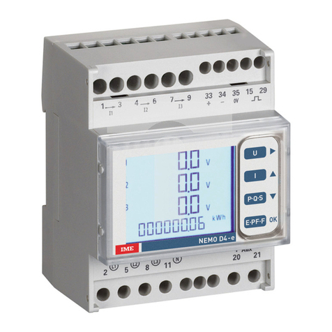
IME Nemo D4-L+ User manual

emo D4-L+
Via Travaglia 7 20094 CORSICO ( I) Tel. 02 44 878.1 Fax 02 45 03 448 +39 02 45 86 76 63 info@imeitaly.com
www.imeitaly.com
03/16 10783521 WEB I cod. F6HT...

03/16 10783521 WEB I cod.MF6HT...
2
emo D4-L+
Multimisura
Misurano
e visualizzano
più grandezze
contemporaneamente
Conteggio
energia
Quantificano
i consumi energetici
Comunicazione
Comunicano le misure
effettuate a distanza
Interfacciano differenti
modi di comunicazione
Misura
e controllo
Misurano
e intervengono
segnalando condizioni
particolari
Indice
Schemi d’inserzione pag.3
Istruzioni per l’installazione pag.3
Programmazione pag.4-5
Verifica sequenza fasi pag.5
Livello 1 Password = 1000
1.0
Password pag.4 e 5
1.1
Azzeramenti pag.4 e 6
1.2
Connessione pag.4 e 6
1.3
Potenza Media pag.4 e 6
1.4
Tempo integrazione corrente e potenza media pag.4 e 6
1.5
Comunicazione RS485 ModBus RTU/TCP o BAC ET pag.4-5 e 7
1.6
Impulsi energia pag.5 e 8
1.7
Contrasto display pag.5 e 8
Livello 2 Password = 2001
2.0
Password pag.5 e 8
2.1
Rapporto TA e TV esterni pag.5 e 8
Visualizzazione
Configurazione trifase 4 fili (3 -3E / 3 -1E) pag. 9
Configurazione trifase 3 fili (3-3E / 3-2E / 3-1E) pag.10
Configurazione monofase (1 -1E) pag.11
Alimentazione Ausiliaria pag.12
Impostazioni di fabbrica pag.12
La documentazione tecnica del prodotto è disponibile sul sito www.imeitaly.c m nell’area “D cumentazi ne tecnica” digitare nel campo “C dice N ta Tecnica: NT695”.
La I.M.E. S.p.A. si riserva in qualsiasi momento, di modificare le caratteristiche tecniche senza darne preavviso.

258 1
11 369
47
S1
P1
I N P U T
a
A
b
B
L
N
LOAD
X
258
11
O U T P U T
33 34 35
RS 485
Rx / Tx GND
+–
15 29 20
AUX.
SUPPLY
21
S 1000/305
1N1E
ATTE ZIO E!
Collegare alimentazione ausiliaria ai terminali 20 e 21.
03/16 10783521 WEB I cod.MF6HT... 3
emo D4-L+
OTA
Negli schemi sono sempre indicate le configurazioni con uscita
impulsi e comunicazione RS485.
Nelle versioni che non prevedono uscita impulsi o comunicazione
RS485 non si deve tenere conto dei relativi collegamenti.
258 1369
47
S1
P1
S1
P1
I N P U T
LOAD
a
A
b
B
a
A
b
B
L1
L2
L3
11
X
X
X
258
O U T P U T
33 34 35
RS 485
Rx / Tx GND
+–
15 29 20
AUX.
SUPPLY
21
258 1
11 369
47
S1
P1 S1
P1
I N P U T
LOAD
a
A
b
B
a
A
b
B
L1
L2
L3 X
X
X
258
O U T P U T
33 34 35
RS 485
Rx / Tx GND
+–
15 29 20
AUX.
SUPPLY
21
S 1000/307
3-2E
(L1-L3)
S 1000/308
3-2E
(L2-L3)
258 1
11 47
S1
P1 S1
P1
I N P U T
LOAD
369
a
A
b
B
a
A
b
B
L1
L2
L3 X
X
X
O U T P U T
33 34 35
RS 485
Rx / Tx GND
+–
15 29
258
20
AUX.
SUPPLY
21
S 1000/306
3-2E
(L1-L2)
F : 0,5A gG
X
X
X
S1
P1 S1
P1
I N P U T
S1
P1
VOLTAGE CURRENT
a
A
b
B
a
A
b
B
L1
L2
L3
LOAD
258
258
11 13 46 79
O U T P U T
33 34 35
RS 485
Rx / Tx GND
+–
15 29 20
AUX.
SUPPLY
21
S 1000/309
3-3E
258 1
11 369
47
I N P U T
LOAD
a
A
b
B
a
A
b
B
L1
L2
L3 X
X
X
258
O U T P U T
33 34 35
RS 485
Rx / Tx GND
+–
15 29 20
AUX.
SUPPLY
21
S1
P1
S 1000/357
3-1E
X
X
X
S1
P1
a
A
L1
L2
L3
N
X X XLOAD
I N P U T
VOLTAGE CURRENT
258
11
258
11 1346 79
O U T P U T
33 34 35
RS 485
Rx / Tx GND
+–
15 29 20
AUX.
SUPPLY
21
S 1000/358
3N1E
X
X
X
S1
P1 S1
P1 S1
P1
a
A
L1
L2
L3
N
X X X
LOAD
I N P U T
VOLTAGE CURRENT
258
11
258
11 1346 79
O U T P U T
33 34 35
RS 485
Rx / Tx GND
+–
15 29 20
AUX.
SUPPLY
21
S 1000/310
3N3E
Istruzioni per l’installazione
Questo prodotto deve essere installato in conformità con le regole d’installazione e
di preferenza da un elettricista qualificato.
L’eventuale installazione impropria e/o utilizzo improprio dello stesso possono
comportare rischi di shock elettrico o incendio.
Prima di procedere all’installazione, leggere attentamente le istruzioni e individuare
un luogo di montaggio idoneo in funzione del prodotto.
on aprire, smontare, alterare o modificare l’apparecchio eccetto speciale menzione
indicata nel manuale. Tutti i prodotti IME devono essere esclusivamente aperti e
riparati da personale adeguatamente formato e autorizzato da IME. Qualsivoglia
apertura o riparazione non autorizzata comporta l’esclusione di eventuali
responsabilità, diritti alla sostituzione e garanzie. Verificare che i dati di targa
dell’apparecchio (tensione di misura, tensione di alimentazione ausiliaria, corrente di
misura, frequenza) corrispondano a quelli effettivi della rete a cui viene collegato lo
strumento. ei cablaggi rispettare scrupolosamente lo schema di inserzione; una
inesattezza nei collegamenti è inevitabilmente causa di misure falsate o di danni allo
strumento. Collegato lo strumento, completare l’installazione con la configurazione
dell’apparecchio.

03/16 10783521 WEB I cod.MF6HT...
4
emo D4-L+
Programmazione
La programmazione è suddivisa su due livelli, protetti da due differenti password numeriche e
avviene tramite tastiera frontale 3 tasti
Aumenta il valore impostato
ella pagine con scelta fra valori fissi, scorre i valori impostabili
Sposta il cursore
Conferma
Livello 1
Password = 1000
1.0
Password
1.1
Azzeramenti
1.2
Connessione
1.3
Potenza media
1.4
Tempo integrazione corrente e potenza media
1.5
Comunicazione RS485 ModBus RTU/TCP o BAC ET (dove prevista)
1.6
Impulsi energia (dove prevista)
1.7
Contrasto display
Livello 2
Password = 2001
2.0
Password
2.1
Rapporto TA e TV esterni
Parametri Programmabili
Livello 1
Password = 1000
1.1
Azzeramenti
Possibilità di azzeramento dei conteggi effettuati
1.1a
Energia Attiva Parziale
1.1b
Picco Corrente Media
1.1c
Picco Potenza Media
1.1d
Contaore (ore e minuti di funzionamento)
La funzione contaore, conteggio ore e minuti di funzionamento, è attiva quando il
dispositivo rileva la presenza della fase L1.
1.2
Connessione
Lo strumento può essere utilizzato per linea monofase o trifase 3 e 4 fili.
Le inserzioni selezionabili sono:
1.3
Potenza media
Potenza associata: attiva, reattiva, apparente
1.4 Tempo integrazione corrente e potenza media
Tempo integrazione selezionabile: 5, 8, 10, 15, 20, 30, 60minuti
Il tempo selezionato, vale sia per la corrente che per la potenza media
1.5
Comunicazione RS485 (dove prevista)
In funzione dei modelli, lo strumento può essere privo di comunicazione oppure dotato
di comunicazione RS485 odBus RTU/TCP o RS485 BACNET
1.5a
Comunicazione RS485 ModBus RTU/TCP
N° indirizzo: 1...255
Velocità trasmissione: 4,8 – 9,6 – 19,2 kbit/s
Bit di parità: nessuna – pari – dispari
Tempo di attesa prima della risposta: 3...100ms
ormalmente è consigliabile impostare 003 (3ms). In caso di assenza di comunicazione,
nell’abbinamento ad altre interfacce, provare ad aumentare il valore.
Simb l Linea Caric n° TA esterni Schema Inserzi ne
1 1E Monofase - 1 S 1000/305
3-1E Trifase 3 fili Equilibrato 1 S 1000/357
3 1E Trifase 4 fili Equilibrato 1 S 1000/358
3-2E Trifase 3 fili Squilibrato 2 S 1000/306 Aron L1 - L2
3-2E Trifase 3 fili Squilibrato 2 S 1000/307 Aron L1 - L3
3-2E Trifase 3 fili Squilibrato 2 S 1000/308 Aron L2 - L3
3-3E Trifase 4 fili Squilibrato 3 S 1000/309
3 3E Trifase 4 fili Squilibrato 3 S 1000/310
Nemo D4-L+
V1
V2
V3
11 25
679
4
3
18

03/16 10783521 WEB I cod.MF6HT... 5
emo D4-L+
1.5b
Comunicazione RS485 BAC ET
Indirizzo: 0...127
Velocità trasmissione: 9,6 – 19,2 – 38,4 - 76,8 kbit/s
Bit di parità: nessuna – pari – dispari
Indirizzo di rete: 0...65535
1.6
Impulsi energia (dove prevista)
Grandezza associabile: energia attiva o reattiva
Peso impulsi: 1imp/0,1kWh(kvarh) - 1kWh(kvarh) - 10kWh(kvarh) – 100kWh(kvarh)
Durata impulso: 50 – 100 – 200 – 300ms
1.7
Constrasto display
Valori selezionabili: 0...10
Livello 2
Password = 2001
2.1
Rapporto TA e TV esterni
Ct = Rapporto primario/secondario TA esterno (es. TA 800/5A Ct = 160)
Vt =Rapporto primario/secondario TV esterno (es. TV 600/100V Vt = 6)
Rapporto TA esterno (Ct): 1...9999
Rapporto TV esterno (Vt): 1,0...400,0
Limite prodotto rapporti TA x TV (Ct x Vt): 100000(TA/5A) – 400000(TA/1A)
Per inserzione diretta in tensione (senza TV esterno) impostare Vt=1,0
Modificando i rapporti TA e/o TV i contatori di energia vengono azzerati
automaticamente.
Verifica sequenza fasi
Premendo il tasto E TER (in una qualsiasi pagina di visualizzazione) si effettua un controllo del corretto
collegamento delle voltmetriche (sequenza fasi).
Se il collegamento è corretto, la visualizzazione non cambia.
Se il collegamento è errato appare la visualizzazione ERR 123.
In questo caso occorre correggere il collegamento delle voltmetriche e ripetere la verifica fino ad
ottenere l’esatta sequenza.
ATTE ZIO E!
Una errata sequenza fasi è causa di errori di misura.
1.0 Password 1000
Tenere premuto i 2 tasti contemporaneamente fino a visualizzare la pagina:
Impostare password 1000 e confermare
sposta il cursore
aumenta il valore impostato
↵conferma

03/16 10783521 WEB I cod.MF6HT...
6
emo D4-L+
1.2 Connessione
seleziona la connessione
↵conferma
Selezionare il tipo di inserzione desiderato, rispettando poi scrupolosamente lo
schema di collegamento abbinato.
Le inserzioni selezionabili sono:
1.3 Potenza media
P tenza ass ciata:
attiva (W),
reattiva
(VAr)
, apparente
(VA)
seleziona la potenza
↵conferma
1.4 Tempo integrazione corrente e potenza media
Temp integrazi ne selezi nabile: 5, 8, 10, 15, 20, 30, 60minuti
Il tempo selezionato, vale sia per la corrente che per la potenza media
seleziona il valore
↵conferma
1.1 Azzeramenti
Possibilità di azzeramento dei conteggi effettuati
1.1a Energia Attiva Parziale
Azzeramento no (no) oppure si (YES)
seleziona no o YES
↵conferma
1.1b Picco Corrente media
Azzeramento no (no) oppure si (YES)
seleziona no o YES
↵conferma
1.1c Picco Potenza media
Azzeramento no (no) oppure si (YES)
seleziona no o YES
↵conferma
1.1d Contaore (ore e minuti di funzionamento)
Azzeramento no (no) oppure si (YES)
seleziona no o YES
↵conferma
Simb l Linea Caric n° TA esterni Schema Inserzi ne
1 1E Monofase - 1 S 1000/305
3-1E Trifase 3 fili Equilibrato 1 S 1000/357
3 1E Trifase 4 fili Equilibrato 1 S 1000/358
3-2E Trifase 3 fili Squilibrato 2 S 1000/306 Aron L1 - L2
3-2E Trifase 3 fili Squilibrato 2 S 1000/307 Aron L1 - L3
3-2E Trifase 3 fili Squilibrato 2 S 1000/308 Aron L2 - L3
3-3E Trifase 4 fili Squilibrato 3 S 1000/309
3 3E Trifase 4 fili Squilibrato 3 S 1000/310

03/16 10783521 WEB I cod.MF6HT... 7
emo D4-L+
1.5 Comunicazione RS485 (dove prevista)
In funzione dei modelli, lo strumento può essere privo di comunicazione o dotato
di comunicazione RS485 ModBus RTU / TCP o RS485 BAC ET.
1.5a Comunicazione RS485 ModBus RTU / TCP
N° indirizz : 1...255
sposta il cursore
aumenta il valore impostato
↵conferma
Vel cità trasmissi ne: 4,8 – 9,6 – 19,2 kbit/s
seleziona valore
↵conferma
Bit di parità: nessuna – pari – dispari
seleziona parità
↵conferma
Temp di attesa prima della risp sta (time-out):3...100ms
sposta il cursore
aumenta il valore impostato
↵conferma
ormalmente è consigliabile impostare 003 (3ms). In caso di assenza di comunica-
zione, nell’abbinamento ad altre interfacce, provare ad aumentare il valore.
1.5b Comunicazione RS485 BAC ET
Indirizz : 0...127
sposta il cursore
aumenta il valore impostato
↵conferma
Vel cità trasmissi ne: 9,6 – 19,2 – 38,4 - 76,8 kbit/s
seleziona valore
↵conferma
Bit di parità: nessuna – pari – dispari
seleziona parità
↵conferma
Indirizz di rete: 0...4000
sposta il cursore
aumenta il valore impostato
↵conferma

03/16 10783521 WEB I cod.MF6HT...
8
emo D4-L+
1.6 Impulsi energia (dove prevista)
Grandezza ass ciabile: energia attiva o reattiva
seleziona attiva / reattiva
↵conferma
Pes impulsi: 1imp/0,1kWh(varh) – 1kWh(kvarh) - 10kWh(kvarh) - 100kWh(kvarh)
seleziona valore
↵conferma
Durata impuls : 50 – 100 – 200 – 300ms
seleziona valore
↵conferma
1.7 Contrasto display
Val ri selezi nabili:1...10
seleziona valore
↵conferma
2.0 Password 2001
Tenere premuto i 2 tasti contemporaneamente fino a visualizzare la pagina:
Impostare password 2001 e confermare
sposta il cursore
aumenta il valore impostato
↵conferma
2.1 Rapporto TA esterni
Ct = Rapporto primario/secondario TA esterno (es. TA 800/5A Ct = 160)
Rapp rt TA estern (Ct): 1...9999
sposta il cursore
aumenta il valore impostato
↵conferma
Rapporto TV esterni
Vt = Rapporto primario/secondario TV esterno (es. TV 600/100V Vt = 6)
Rapp rt TV estern (Vt): 1,0...400,0
sposta il cursore
aumenta il valore impostato
↵conferma
Limite prodotto rapporti TA x TV (CtxVt): 100000 (TA/5A) - 400000(TA/1A)
Per inserzione diretta in tensione (senza TV esterno) impostare Vt =1,0
Modificando i rapporti TA e/o TV i contatori di energia vengono
azzerati automaticamente.

03/16 10783521 WEB I cod.MF6HT... 9
emo D4-L+
3 3E - 3 1E

03/16 10783521 WEB I cod.MF6HT...
10
emo D4-L+
3-3E 3-2E 3-1E

03/16 10783521 WEB I cod.MF6HT... 11
emo D4-L+
1 1E

03/16 10783521 WEB I cod.MF6HT...
12
emo D4-L+
Terminali 20 e 21
Alimentazione Ausiliaria: alimentazione elettrica in ca o in cc necessaria per il
corretto funzionamento del dispositivo.
Verificare che la tensione di alimentazione disponibile, corrisponda a quella indicata sulla
targa dati dello strumento (valore di tensione ed eventuale frequenza).
Dove viene indicata una doppia tensione (es. 48Vca / 20...150Vcc) lo strumento può
essere alimentato con tensione alternata 48Vca o tensione continua 20...150Vcc.
In caso di alimentazione in tensione continua rispettare le polarità indicate 20+ e21-.
F : 0,5A gG
Alimentazione Ausiliaria
I N P U T
VOLTAGE CURRENT
258
11 1346 79
O U T P U T
33 34 35
RS 485
Rx / Tx GND
+–
15 29 20
AUX.
SUPPLY
21
Impostazioni di fabbrica
Password 1000
Connessione: 3n3E linea 4 fili 3 sistem
Tempo media: W
Tempo integrazione: 15m 15Minuti
RS485
Indirizzo: 255
Velocità: 9.6k
Parità: nonE
Time-out: 3mS
BAC ET
Indirizzo dispositivo: 01
Velocità: 9.6k
Parità: nonE
Indirizzo di rete: 0010
Uscita Impulsi
Energia: Wh
Peso impulso: 0,1kWh
Durata impulso: 50ms
Contrasto display: 0010
Password 2001
Rapporto TA: 0001
Rapporto TV: 001,0

Nemo D4-L+
Via Travaglia 7 20094 CORSICO (MI) Tel. 02 44 878.1 Fax 02 45 03 448 +39 02 45 86 76 63 info@imeitaly.com
www.imeitaly.com
03/16 10783521 WEB E cod.MF6HT...

03/16 10783521 WEB E cod. F6HT...
2
Nemo D4-L+
Index
Schemi d’inserzione page 3
Istruzioni per l’installazione page 3
Programmazione page 4-5
Phase sequence checking page 5
Level 1 Password = 1000
1.0
Password page 4 and 5
1.1
Resets page 4 and 6
1.2
Connection page 4 and 6
1.3
Power Demand page 4 and 6
1.4
Current delay time and average power page 4 and 6
1.5
RS485 odBus RTU/TCP or BACNET communication page 4-5 and 7
1.6
Energy Pulse page 5 and 8
1.7
Display Contrast page 5 and 8
Level 2 Password = 2001
2.0
Password page 5 and 8
2.1
External CT and VT ratio page 5 and 8
Display
3-phase 4 wires configuration (3N-3E / 3N-1E) page 9
3-phase 4 wires configuration (3-3E / 3-2E / 3-1E) page 10
Single-phase configuration (1N-1E) page 11
Auxiliary Supply page 12
Factory settings page 12
ultimetering
They measure and
display simultaneously
more quantities
Energy counting
They quantify the
energy consumption
Communication
They communicate the
measurements carried
at a distance
Interface different
ways of communication
easuring and
onitoring
They measure and
report specific
involved conditions
I.M.E. S.p.A. reserves the right, to modify the technical characteristics without notice.
The technical documentation for the product is available on www.imeitaly.com website in the “Tech ical docume tatio ” area, type in the field “Tech ical ote code NT695”.

258 1
11 369
47
S1
P1
I N P U T
a
A
b
B
L
N
LOAD
X
258
11
O U T P U T
33 34 35
RS 485
Rx / Tx GND
+–
15 29 20
AUX.
SUPPLY
21
S 1000/305
1N1E
ATTENTION!
Aux. supply must be connected to terminals 20 and 21
03/16 10783521 WEB E cod. F6HT... 3
Nemo D4-L+
NOTE
The wiring diagrams show the device complete with pulse output
and RS485 interface.
In case of version without these features, the corresponding ter-
minals must not be considered.
258 1369
47
S1
P1
S1
P1
I N P U T
LOAD
a
A
b
B
a
A
b
B
L1
L2
L3
11
X
X
X
258
O U T P U T
33 34 35
RS 485
Rx / Tx GND
+–
15 29 20
AUX.
SUPPLY
21
258 1
11 369
47
S1
P1 S1
P1
I N P U T
LOAD
a
A
b
B
a
A
b
B
L1
L2
L3 X
X
X
258
O U T P U T
33 34 35
RS 485
Rx / Tx GND
+–
15 29 20
AUX.
SUPPLY
21
S 1000/307
3-2E
(L1-L3)
S 1000/308
3-2E
(L2-L3)
258 1
11 47
S1
P1 S1
P1
I N P U T
LOAD
369
a
A
b
B
a
A
b
B
L1
L2
L3 X
X
X
O U T P U T
33 34 35
RS 485
Rx / Tx GND
+–
15 29
258
20
AUX.
SUPPLY
21
S 1000/306
3-2E
(L1-L2)
F : 0,5A gG
X
X
X
S1
P1 S1
P1
I N P U T
S1
P1
VOLTAGE CURRENT
a
A
b
B
a
A
b
B
L1
L2
L3
LOAD
258
258
11 13 46 79
O U T P U T
33 34 35
RS 485
Rx / Tx GND
+–
15 29 20
AUX.
SUPPLY
21
S 1000/309
3-3E
258 1
11 369
47
I N P U T
LOAD
a
A
b
B
a
A
b
B
L1
L2
L3 X
X
X
258
O U T P U T
33 34 35
RS 485
Rx / Tx GND
+–
15 29 20
AUX.
SUPPLY
21
S1
P1
S 1000/357
3-1E
X
X
X
S1
P1
a
A
L1
L2
L3
N
X X XLOAD
I N P U T
VOLTAGE CURRENT
258
11
258
11 1346 79
O U T P U T
33 34 35
RS 485
Rx / Tx GND
+–
15 29 20
AUX.
SUPPLY
21
S 1000/358
3N1E
X
X
X
S1
P1 S1
P1 S1
P1
a
A
L1
L2
L3
N
X X X
LOAD
I N P U T
VOLTAGE CURRENT
258
11
258
11 1346 79
O U T P U T
33 34 35
RS 485
Rx / Tx GND
+–
15 29 20
AUX.
SUPPLY
21
S 1000/310
3N3E
ounting instructions
This product must be mounted according to the mounting rules and preferably by a
skilled electrician. Possible wrong mounting and/or misuses of the device may
involve the risk of electric shock or fire.
Before mounting, please carefully read the instructions and find a mounting place
which fits its functions.Do not open, dismantle, tamper or modify this device except
for the special mention reported in the manual.
All the I E’s products must be opened and repaired only by personnel properly
trained and authorized by I E.
Any unauthorized opening or repair leads to the exclusion of every responsibility,
rights to replacement and guarantees.
Please make sure that the data on the label (measuring voltage, extra supply
voltage, measuring current, frequency) correspond to the network on which the
meter must be connected.
In the wiring scrupulously respect the wiring diagram; an error in connection
unavoidably leads to wrong measurements or damages to the device.
When the meter is connected, conclude the mounting with the configuration as de-
scribed in the user's manual.

03/16 10783521 WEB E cod. F6HT...
4
Nemo D4-L+
Programming
enu is divided on two levels, protected by two different numerical passwords.
Programming is carried out by front keyboard 3-key
Increases the loaded value
In the pages with choice among the fixed values, it scrolls the
loadable values
oves the cursor
Confirms
Level 1
Password = 1000
1.0
Password
1.1
Resets
1.2
Connection
1.3
Average power
1.4
Current delay time and average power
1.5
RS485 odBus RTU/TCP or BACNET communication (where provided)
1.6
Energy pulses (where provided)
1.7
Display contrast
Level 2
Password = 2001
2.0
Password
2.1
External CT and VT ratio
Programmable Parameters
Level 1
Password = 1000
1.1
Resets
Possibility to reset the performed counts
1.1a
Partial Active energy
1.1b
Current ax Demand
1.1c
Power ax Demand
1.1d
Hour eter (working minutes and hours)
Run hour function, working minutes and hour counting, is operating when the device
detects L1 phase.
1.2
Connection
The meter can be used for single phase or three phase 3- and 4-wire network.
The selectable connections are:
1.3
Power demand
Combined power: active, reactive, apparent
1.4 Current delay time and average power
Selectable delay time: 5, 8, 10, 15, 20, 30, 60 minutes
The selected time is valid both for the current and the average power
1.5
RS485 communication (where provided)
According to the models, this meter can be without communication or equipped with
RS485 ModBus RTU/TCP or RS485 BAC ET communication
1.5a
RS485 odBus RTU/TCP communication
Address number 1...255
Transmission speed: 4,8 – 9,6 – 19,2 kbit/s
Parity bit: none – even – odd
Waiting time before answer: 3...100ms
It is usually advisable to load 003 (3ms). If, in the connection to other interfaces the
communication is lacking, try to increase the value.
Symbol Li e Load
°CT exter al
Wiri g Co ectio
1N1E Single-phase - 1 S 1000/305
3-1E 3-phase 3 wires Balanced 1 S 1000/357
3N1E 3-phase 4 wires Balanced 1 S 1000/358
3-2E 3-phase 3 wires Unbalanced 2 S 1000/306 Aron L1 - L2
3-2E 3-phase 3 wires Unbalanced 2 S 1000/307 Aron L1 - L3
3-2E 3-phase 3 wires Unbalanced 2 S 1000/308 Aron L2 - L3
3-3E 3-phase 4 wires Unbalanced 3 S 1000/309
3N3E 3-phase 4 wires Unbalanced 3 S 1000/310
Nemo D4-L+
V1
V2
V3
11 25
679
4
3
18

03/16 10783521 WEB E cod. F6HT... 5
Nemo D4-L+
1.5b
RS485 BACNET communication
Address number: 0...127
Transmission speed: 9,6 – 19,2 – 38,4 - 76,8 kbit/s
Parity bit: none – even – odd
etwork address: 0...65535
1.6
Energy pulses (where provided)
Quantity that can be coupled: active or reactive energy
Pulse weight: 1imp/0,1kWh(kvarh) - 1kWh(kvarh) - 10kWh(kvarh) – 100kWh(kvarh)
Width of the pulse: 50 – 100 – 200 – 300ms
1.7
Display contrast
Selectable values: 0...10
Level 2
Password = 2001
2.1
External VT and CT ratio
Ct = External primary/secondary CT ratio (ex. CT 800/5A Ct = 160)
Vt =External primary/secondary VT ratio (ex. VT 600/100V Vt = 6)
External CT ratio (Ct): 1…9999
External VT ratio (Vt): 1,0…400,0
Limit produced ratios
CT x VT (Ct x Vt): 100000(CT/5A) – 400000(CT/1A)
For voltage direct connection (with external voltage transformer) load Vt=1,0
By modifying the CT and/or VT ratios, the KWH meters are automatically reset
Phase sequence checking
Pressing ENTER key (in any of the display pages) you can check the correct connection of the voltme-
tric (phase sequence).
If the connection is right, the display doesn’t change.
If the connection is wrong, Err 123 is displayed. In the case you have to modify the voltmetric
connection and repeat the checking until you get the correct sequence.
ATTENTION!
A wrong phase sequence may leads to measuring errors.
1.0 Password 1000
Keep simultaneously pressed the 2 keys until you display page:
Load password 1000 and confirms
moves the cursor
increases the loaded value
↵confirms

03/16 10783521 WEB E cod. F6HT...
6
Nemo D4-L+
1.2 Connection
selects the connection
↵Confirms
Select the desired connection and scrupulously respect the linked wiring diagram.
The selectable wiring diagrams are:
1.3 Power Demand
Combi ed power:
activa (W),
reactiva
(VAr)
, apparent
(VA)
selects power
↵confirms
1.4 Current delay time and average power
Selectable delay time: 5, 8, 10, 15, 20, 30, 60 minutes
The selected time is valid both for the current and the average power
selects the time value
↵confirms
1.1 Resets
Possibility to reset the performed counts
1.1a Partial Active Energy
Reset no (no) or yes (YES)
selects no or YES
↵confirms
1.1b Current ax. Demand
Reset no (no) or yes(YES)
selects no or YES
↵confirms
1.1c Power ax. Demand
Reset no (no) or yes(YES)
selects no or YES
↵confirms
1.1d Run Hour eter (working hours and minutes)
Reset no (no) or yes(YES)
selects no or YES
↵confirms
Symbol Li e Load
°CT exter al
Wiri g Co ectio
1N1E Single-phase - 1 S 1000/305
3-1E 3-phase 3 wires Balanced 1 S 1000/357
3N1E 3-phase 4 wires Balanced 1 S 1000/358
3-2E 3-phase 3 wires Unbalanced 2 S 1000/306 Aron L1 - L2
3-2E 3-phase 3 wires Unbalanced 2 S 1000/307 Aron L1 - L3
3-2E 3-phase 3 wires Unbalanced 2 S 1000/308 Aron L2 - L3
3-3E 3-phase 4 wires Unbalanced 3 S 1000/309
3N3E 3-phase 4 wires Unbalanced 3 S 1000/310

03/16 10783521 WEB E cod. F6HT... 7
Nemo D4-L+
1.5 RS485 Communication (where provided)
According to the models, this meter can be without communication or equipped with
RS485 odBus RTU / TCP or RS485 BACNET communication.
1.5a RS485 odBus RTU / TCP Communication
Address umber: 1...255
oves the cursor
increases the loaded value
↵confirms
Tra smissio speed: 4,8 – 9,6 – 19,2 kbit/s
selects speed
↵confirms
Parity bit: none – even – odd
selects parity
↵confirms
Waiti g time before a swer (time-out):3...100ms
moves the cursor
increases the loaded value
↵confirms
It is usually advisable to load 003 (3ms). If, in the connection to other interfaces the
communication is lacking, try to increase the value.
1.5b RS485 BACNET Communication
Address: 0...127
moves the cursor
increases the loaded value
↵confirms
Tra smissio speed: 9,6 – 19,2 – 38,4 - 76,8 kbit/s
selects speed
↵confirms
Parity bit: none – even – odd
selects parity
↵confirms
Network address: 0...4000
moves the cursor
increases/decreases the loaded value
↵confirms

03/16 10783521 WEB E cod. F6HT...
8
Nemo D4-L+
1.6 Energy pulses (where provided)
Qua tity that ca be coupled: active or reactive energy
selects active / reactive
↵confirms
Pulse weight:
1Pulse /0,1kWh(varh) – 1kWh(kvarh) - 10kWh(kvarh) - 100kWh(kvarh)
selects pulse weight
↵confirms
Width of the pulse: 50 – 100 – 200 – 300ms
selects width of the pulse
↵confirms
1.7 Display Contrast
Selectable values:1...10
selects the value
↵confirms
2.0 Password 2001
Keep simultaneously pressed the 2 keys until you display page:
Load password 1000 and confirms
moves the cursor
increases the loaded value
↵confirms
2.1 External CT ratio
Ct = external primary/secondary CT ratio (ex.: CT 800/5A Ct = 160)
Exter al CT ratio (Ct): 1…9999
moves the cursor
increases the loaded value
↵confirms
Rapporto TV esterni
Vt =
external primary/secondary VT ratio
(ex.: TV 600/100V Vt = 6)
Exter al VT ratio
(Vt): 1,0...400,0
moves the cursor
increases the loaded value
↵confirms
Limit produced ratios CT x VT (CtxVt): 100000 (CT/5A) - 400000(CT/1A)
For voltage direct connection (with external voltage transformer) load Vt=1,00
By modifying the CT and/or VT ratios, the KWH meters are automatically
reset.
Table of contents
Languages:
Other IME Multimeter manuals
