Master audio DSP206 User manual

DSP206
DSP608
Software DSPLink 10
Pol. Ind. Norte - Perpinyà, 25
08226 TERRASSA (Barcelona-SPAIN)
Copyright © 2014
All rights reserved www.master-audio.com
Apr / Abr 14
User’s Manual / Manual usuario

Master Audio
DSP206-608. Version 1.2 Apr 14 2
ENGLISH
Safety Instructions
1. READ THESE INSTRUCTIONS
All the safety and operating instructions should be read before the product is
operated.
2. KEEP THESE INSTRUCTIONS
The safety and operating instructions should be retained for future reference.
3. HEED ALL WARNINGS
All warnings on the product and in the operating instructions should be adhered to.
4. FOLLOW ALL INSTRUCTIONS
All operating and use of instructions should be followed.
5. DO NOT USE THIS APPARATUS NEAR WATER
Do not use the product near water. For example, near a bathtub, washbowl, kitchen
sink, or laundry tub, in a wet basement, or near a swimming pool, and the like.
6. CLEAN ONLY WITH DRY CLOTH
Unplug the unit from the wall outlet before cleaning. Do not use liquid cleaners or
aerosol cleaners. Use a damp cloth for cleaning.
7. DO NOT BLOCK ANY VENTILATION OPENINGS
Slots and openings in the cabinet back or bottom are provided for ventilation, to
ensure reliable operation of the limit and to protect it from overheating. These
openings must not be blocked or covered. The openings should never be blocked by
placing the product on a bed, sofa, rug, or similar surface. This product should never
be placed near or over a radiator or heat source. This product should not be placed in
a built-in installation such as a bookcase or rack unless proper ventilation is provided
or the manufacture's instructions have been adhered to.
8. DO NOT INSTALL NEAR ANY HEAT SOURCES
This Product should be situated away from heat sources such as radiators, stoves, or
other products (including amplifiers) that produces heat.
9. DO NOT DEFEAT THE SAFETY PURPOSE OF THE POLARIZED OR
GROUNDING-TYPE PLUG
A Polarized plug has two blades with one wider than the other. A grounding-type plug
has two blades and a third grounding prong. The wide blade or the third prongs are
provided for your safety. If the provided plug does not fit into your outlet, consult an
electrician for replacement of the obsolete outlet.
CAUTION
RISK OF ELECTRIC SHOCK
DON’T OPEN
To reduce the risk of fire or electric shock do
not expose this equipment to rain or moisture
WARNING:

Master Audio
DSP206-608. Version 1.2 Apr 14 3
10. PROTECT THE POWER CORD FROM BEING WALKED ON OR PINCHED
PARTICULARLY AT PLUGS, CONVENIENCE RECEPTACLES, AND THE POINT
WHERE THEY EXIT FROM THE APPARATUS.
11. ONLY USE ATTACHMENTS/ ACCESSORIES SPECIFIED BY THE
MANUFACTURER.
12. UNPLUG THIS APPARATUS DURING LIGHTNING STORMS OR WHEN
UNUSED FOR LONG PERIODS OF TIME.
For added protection for this unit during a lightning storm, or when it is left unattended
and unused for long periods of time, unplug it from the wall outlet and disconnect the
antenna or cable system. This will prevent damage to the unit due to lightning and
power line surges.
13. REFER ALL SERVICING TO QUALIFIED SERVICE PERSONNEL. SERVICING
IS REQUIRED WHEN THE APPARATUS HAS BEEN DAMAGED IN ANYWAY,
SUCH AS WHEN THE POWER SUPPLY CORD OR PLUG IS DAMAGED, LIQUID
HAS BEEN SPILLED OR OBJECTS HAVE FALLEN INTO THE APPARATUS, THE
APPARATUS HAS BEEN EXPOSED TO RAIN OR MOISTURE, DOES NOT
OPERATE NORMALLY, OR HAS BEEN FROPPED.
14. WARNING: TO REDUCE THE RISK OF FIRE OR ELECTRIC SHOCK, DO NOT
EXPOSE THIS APPARATUS TO RAIN OR MOISTURE.
15. APPARATUS SHALL NOT BE EXPOSED TO DRIPPING OR SPLASHING AND
NO OBJECTS FILLED WITH LIQUIDS, SUCH AS VASES, SHALL BE PLACED ON
THE APPARATUS.

Master Audio
DSP206-608. Version 1.2 Apr 14 4
1 INTRODUCTION
The DSP206/608 is a complete digital loudspeaker management system designed for
the touring or fixed sound installation markets. The absolute latest in available
technology is utilized with 64-bit floating point processors and high performance 24-
bit Analogue Converters. The high-bit DSP prevents noise and distortion induced by
truncation errors of the commonly used 24-bit fixed-point devices. A complete set of
parameters include I/O levels, 2 second-delay per channel, polarity, 10 bands of
parametric EQ per channel, multiple crossover selections, full function compressor
and peak limiter. Precise frequency control is achieved with its 1 Hz resolution. Inputs
and outputs can be routed in multiple configurations to meet any requirements.
The DSP206/608 can be controlled or configured in real time on the front panel or
with the intuitive PC/Mac GUI accessed via the USB interface (also Ethernet in
DSP608). Software upgrade for CPU and DSP via PC keeps the device current with
newly developed algorithms and functions once available.
Multiple setup storage and system security complete this professional package.
Shipped contents:
-DSP206/608 unit
-AC power cord
-USB cable for PC connection
-4 x rubber feet
-Pen Drive (USB) or CD-ROM with software and User Manual
2 FEATURES
2.1 Common features
-Electronically balanced inputs
-Matched-impedance balanced outputs
-64-bit floating point DSP
-High Performance 24-bit A/D Converters
-1 Hz Frequency Resolution
-10 Parametric Equalizers for each Input and Output
(EQs can be set as Bell,
Notch, High Shelf, Low Shelf, Notch, Allpass, Band Pass, High Pass, Low Pass)
-Multiple Crossover types:
Butterworth, Bessel, Linkwitz-Riley, up to 4
th
order
(24dB / oct).
-Up to 2 seconds delay per each input/output
-RMS compressor and ultra-fast attack Peak Limiter.
-Precise Level, Polarity and Delay
-2-Line x 16 Character Blue Backlit LCD Display
-Signal LED’s on every Input and Output
-Security Lock
-USB Interface for PC/Mac Control and Configuration (on front panel)
-CPU and DSP firmware upgrade via PC/Mac interface

Master Audio
DSP206-608. Version 1.2 Apr 14 5
2.2 Model-specific features:
DSP206
-2 Inputs and 6 Outputs with flexible routing
-110dB dynamic range (inputs) / 114dB dynamic range (outputs)
-48kHz sampling rate
-Low latency (1.32ms)
-Storage of up to 50 Program Setups
DSP608
-4 Analog Inputs, 2 Digital Inputs (AES/EBU) and 8 Outputs with flexible routing.
-118dB dynamic range (inputs) / 114dB dynamic range (outputs)
-65kHz sampling rate
-Low latency (1ms)
-Ethernet connection (RJ45, on back panel)
-Storage of up to 80 Program Setups
3 MAIN CONTROLS AND CONNECTIONS
3.1 The front panel
A) USB Connector – A standard type B USB connector for interface with a PC or
Mac. Software and driver must be installed prior to usage.
B) Mute keys – Press for Mute/Unmute input and output channels. When a channel
is muted, this key will light up in red for indication.
C) Input signal LEDs - Show the current level of the Signal: Signal (-48dBu), -6dBu,
Limit (orange), Clip (red). The Limit led lights up if a gain reduction is taking place
(due to a programmed compressor). The Clip LED references to the device's
maximum headroom (+22dBu).
D) Menu Control keys - There are 6 menu keys: <Channel (Previous Channel),
Channel> (Next Channel), <Select (Previous Option), Select> (Next Option), Menu
and Exit. The functions of each key is explained below:
<Channel: Choose previous channel for editing.
Channel>: Choose next channel for editing
F
E
G
B
C
D
A
H

Master Audio
DSP206-608. Version 1.2 Apr 14 6
<Select: Select previous parameter for editing
Select>: Select next parameter for editing
Menu: This key has different functions depending on when it is used:
In the Main Screen: Access the System Menu.
In the Main Menu allows entering the System Menu.
Exit: Exit to the Main Menu
E) LCD - Shows all the necessary information to control the unit.
F) Copy/Paste keys – Currently no function assigned. For future implementation.
G) Rotary Thumb Wheel – Turn the wheel to change parameter data values. Click
on it to confirm the value entered. The center click of the wheel is also use to
browse different parameters of the same feature.
H) Output signal LEDs - Show the current level of the output Signal: Signal (-
48dBu), -6dBu, Limit (orange), Clip (red). The Limit led lights up if a gain reduction
is taking place (due to a programmed compressor). The Clip LED indicates a gain
this reduction is higher than 12dB.
3.2 The rear panel
DSP206
DSP608
A) Power switch - Controls power On/Off.
B) Main Fuse – T315mA-250V. Slow blow type.
C) Main Power - Connects via a standard IEC socket. A compatible power cord is
supplied with the unit. The input voltage range is 200 to 240VAC, 50-60Hz.
D) XLR input and outputs - Separate 3-pin XLR connectors are provided for each
audio input and output. The device's output stage employs the balanced
impedance topology. All I/O connectors have pin 1 as ground (shield), pin 2 as +
and pin 3 as -.
F
E
B
C
D
A
D

Master Audio
DSP206-608. Version 1.2 Apr 14 7
DSP608 only
E) Ethernet port – RJ45 connector to connect with the PC via Ethernet. Use CAT-5
or CAT-6 cable.
F) AES/EBU Input – This XLR connector accepts a 2-channel digital input in
AES/EBU or S/PDIF format, 16 or 24-bit. Supported sample rates are 44.1, 48,
88.2 and 96 kHz.
4 QUICK INSTALLATION
4.1 Before you start
Before powering up the unit, make sure that the input and output XLR cables are in
good state and following the following pinning diagram: 1 for shield, 2 for live(+), 3 for
return (-) as defined by the AES14 standard.
Do not connect the unit to your computer before installing the software and the USB
Driver. Please refer to installation instructions in this manual.
When connecting the DSP to the amplifiers, mute the DSP outputs (or turn down the
amplifier’s volume knobs) until you configure your processing. Loudspeakers may be
damaged due to a wrong setup. It is advisable to unmute first the high frequency
channels: in case they are connected to low frequency drivers by mistake, they
cannot be damaged. Otherwise, high frequency speakers may be damaged because
of trying to reproduce low frequencies.
4.2 Power Up
After powering up the unit, all LEDs will be lit for about six seconds, while the
following message is displayed on the LCD:
After that, the DSP unit displays its main screen:
Now the DSP unit is ready to operate. The screen shows the name of the unit (above
line) and the program name currently active (below line). The program assigned is
always the last program the user recalled or stored before powering down the unit.
An admiration mark (!) beside the program name means that the program has been
modified but not stored. This symbol does not appear when the modified program is
the default preset.
Initialising...
DEFAULT PRESET
MASTER AUDIO
! My_Preset
MASTER AUDIO

Master Audio
DSP206-608. Version 1.2 Apr 14 8
4.3 Control Software
4.3.1 Introduction
The DSP units are shipped with a Computer Software which provides a Graphic User
Interface (GUI) application - DSPLink. DSPLink allows the user to control the DSP
unit from a computer via the USB communication link (or additionally through
Ethernet, in model DSP608). For the USB connection, a driver must be installed
(included with the DSPLink installation package).
The GUI application makes it much easier to control and monitor the device, allowing
the user to get the whole picture on one screen. Programs can be recalled and stored
from/to Computer’s hard drive, thus expanding the storage to become virtually
limitless.
DSPLink is available for PC and Mac. A USB pen drive or CD-ROM with the software
is included in the original package of the unit Check Master Audio’s website for a
latest version download (www.master-audio.com).
4.3.2 Installation for PC-Windows
Double click the installation file, depending whether you have a 32 or a 64-bit system:
Master_Audio_DSPLink_32_bit_v_10_X_X_BuildNr.msi
Master_Audio_DSPLink_64_bit_v_10_X_X_BuildNr.msi
Follow the on-screen instructions. You may be prompted to install the Microsoft
Visual Runtime libraries before finishing the installation. Click the checkbox to
proceed with this action.
NOTE: Installations under Windows 8 (or newer) require configuring Windows to
accept the installation of drivers without digital signature. Should you need support in
that, please refer to section 8.1 of this manual.
4.3.3 Installation for Mac
First unzip the provided installation file:
Master_Audio_DSPLink_v_10_X_X_BuildNr.mpkg.zip

Master Audio
DSP206-608. Version 1.2 Apr 14 9
Then select the .mkpg file with CONTROL+Click and select “Open”. Then follow the
on-screen instructions.
4.4 Connecting the device to a computer
4.4.1 USB
WARNING: Always install the software package DSPLink before connecting your unit
to the computer. See previous section for details.
After installing DSPLink, please use the provided USB cable to connect the unit to
your computer. The first time you connect a device, the system will ask you to look for
the driver. Choose the option “do not look for updates and to automatically select the
best driver”.
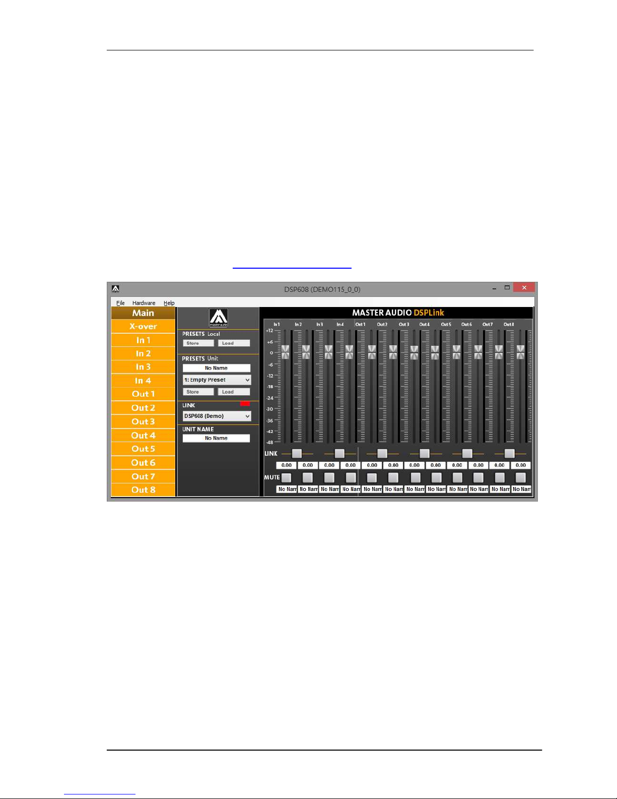
Run DSPLink and the unit will be automatically detected.
Click on the arrow next to the detected unit to open the window for parameter edition.
4.4.2 Ethernet (DSP608 only)
Use a standard CAT5 or CAT6 cable with RJ45 connectors (not supplied) to connect
the unit to your Local Area Network. The most convenient way is to connect it to a
router that provides automatic IP addresses (DHCP enabled), and that is sharing the
same network with the computer in which you are running DSPLink. In this case the
unit will be detected and configured automatically.
For direct connection with a computer, or through a switch not supporting DHCP, then
you can either let your computer get an automatic IP of the ZeroConfig range, or
assign a fixed IP to it:
To obtain an automatic IP in the ZeroConfig range:
1. Connect the unit to the switch or computer. The computer network card’s
settings must specify “Obtain an automatic IP” (by default)
2. DSPLink will detect the unit through its MAC address.
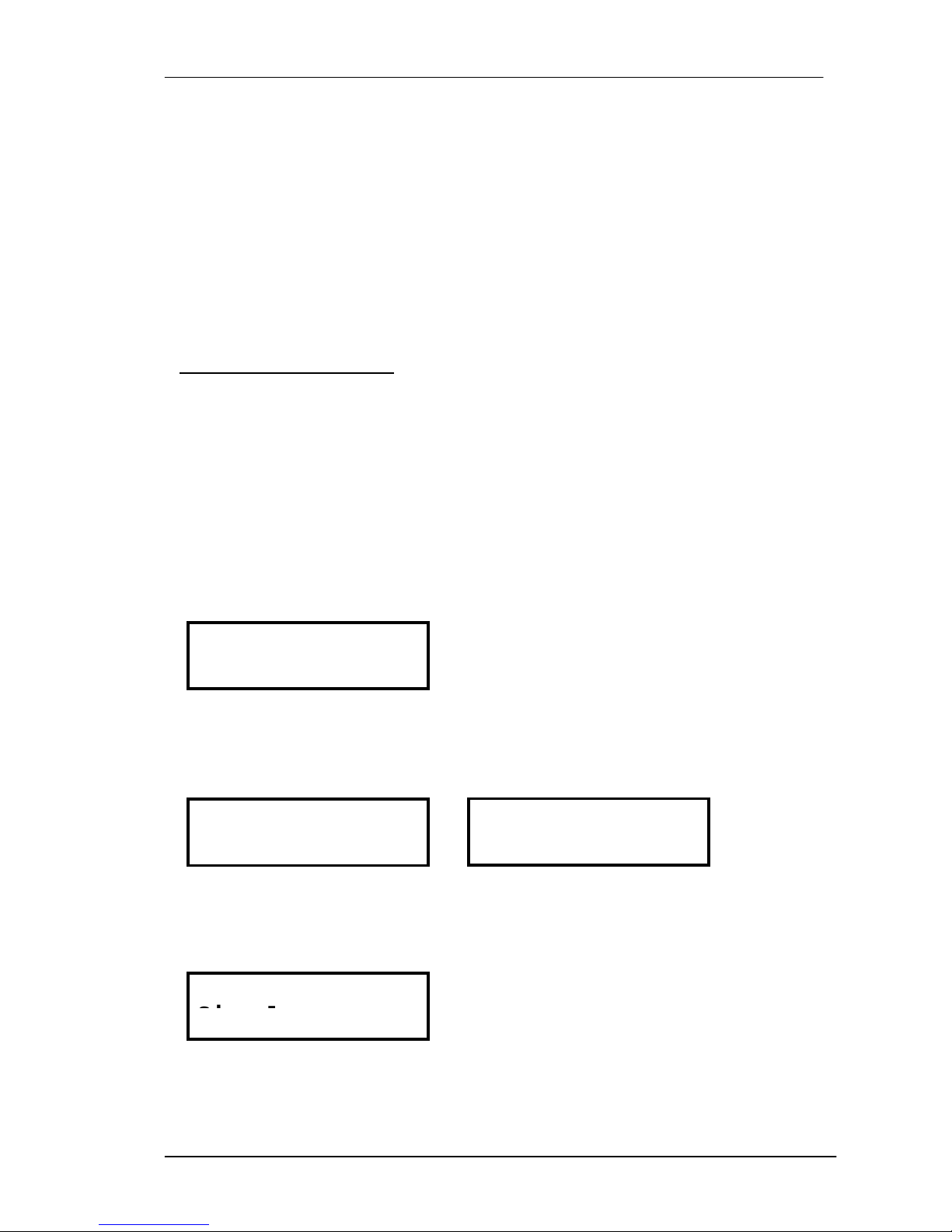
3. After some time (it may take a couple of minutes), the system will assign the
address and notify the message “This connection has limited or no
connectivity”.
To set a fixed IP in the ZeroConfig range:
1. Open your Network Connection settings and edit TCP/IP address
2. Set the IP in the ZeroConfig Range (169.254.0.0 – 169.254.255.255)
3. Set a Subnet Mask as 255.255.0.0.
4. Other parameters such as Gateway or DNS Servers may be left blank.
5. Connect the unit to the network where your computer is connected to.
6. DSPLink will detect the unit
4.5 System Optimization
In order to have a proper start of your system and an optimized configuration, follow
these steps by the first configuration:
1. Play a signal at the nominal level from your mixing desk, and set the input gain
of your processor to 0dB (Default Preset setting)
2. Set the crossovers that you want to use, while keeping the output gains also at
0dB.

Master Audio
DSP206-608. Version 1.2 Apr 14 10
3. With DISCONNECTED loudspeakers, turn up the volume of the power
amplifiers entirely clockwise (full volume).
4. Reduce the output gain and / or the output limiter setting to get the desired
gain, so that the amplifier is just clipping and the built-in limiters of your
processor are just limiting (Orange led blinking at the output channels).
5. Turn down the volume of the power amplifiers, connect your speakers, and
slowly increase the volume while checking the sound.
6. Check if the loudspeakers are reproducing distortion-free sound, and the
limiter LEDs are flashing or off, but not continuously on. If they are
continuously on, reduce the output gain of your processor.
7. If you cannot reach enough signal level, increase the processor's input gain or
turn up the level from your mixing desk.
5 OPERATING THE DEVICE
5.1 Input Menus
To access the Input Menus press the <Channel or Channel> key. Press Exit to finish
editing or again <Channel or Channel> to edit other channels.
The following menus are available for each input channel. Please note that by default
the inputs and outputs channels are linked in groups of two. The following options are
shown for the input group composed of In1 and In2
5.1.1 Input Gain
Adjust the gain of each input, using the rotary knob.
5.1.2 Input Selection
Select an analog or digital source (AES/EBU) using the rotary knob.
(This option is only available in DSP608).
5.1.3 Delay
Adjust the delay by turning the rotary knob. Push this knob to switch the unit between
ms, ft or m.
5.1.4 Crossover
• Low Pass – First adjust the Low Pass Filter cut-off frequency. To switch it off, turn
the rotary knob clockwise until frequency reaches 20 kHz.
-
1.25dB
In 12 Gain
Analog
In 12 Source
0.090ms
In 12 Delay
Signal
AES Stereo
In 12 Source

Master Audio
DSP206-608. Version 1.2 Apr 14 11
Second, press the rotary knob and select from the available types and slopes:
Type: Butterworth, Slopes: 6dB, 12dB, 18dB or 24dB
Type: Bessel. Slopes: 6dB, 12dB, 18dB or 24dB
Type: Linkwitz-Riley. Slope: 12dB or 24dB
• High Pass – First adjust the High Pass Filter cut-off frequency. To switch it off, turn
the rotary knob counter-clockwise until frequency reaches 20 Hz.
Second, press the rotary knob and select from the available types and slopes:
Type: Butterworth, Slopes: 6dB, 12dB, 18dB or 24dB
Type: Bessel. Slopes: 6dB, 12dB, 18dB or 24dB
Type: Linkwitz-Riley. Slope: 12dB or 24dB
5.1.5 Parametric EQ
Select between one of the 10 available Equalizers on each input channel by using the
keys < Select and Select >. Browse the parameters by turning the rotary knob and
push the knob to select and confirm the values. The following parameters can be
adjusted for each EQ:
• Freq - EQ center frequency.
• Gain - EQ level gain.
• Q- EQ Bandwidth. For shelving filters the Q sets the transition in dB/Oct.
• Type - Shape of EQ. The available types are:
Bell: Modifies the gain of a certain frequency range, with bell shape
Notch: Eliminates a range around a center frequency
Low-Shelf: Modifies the gain of all the range below a selected frequency.
High-Shelf: Modifies the gain of all the range above a selected frequency.
All Pass: Modifies the phase response, without influencing the frequency response.
Band Pass: Filters out all the range except the defined band.
High Pass: Filters out all the range below a certain frequency.
Low Pass: Filters out all the range above a certain frequency.
• Enabled – When set On, the currently selected EQ is on line.
Q: 2.36
In 12 PEQ 1
Freq: 15000Hz
In 12 LowPass
XOver
Type: BUT 24dB
In 12 LowPass
XOver
Type: BUT 24dB
In 12
HighPass
XOver
Freq: 40Hz
In 12 High
Pass
XOver
Type: Bell
In 12 PEQ 1
Freq: 1000Hz
In 12 PEQ 1
Gain: 0.00dB
In 12 PEQ 1

Master Audio
DSP206-608. Version 1.2 Apr 14 12
5.1.6 Dynamics Compressor
A true RMS compressor can be set to avoid the input signal go above a certain RMS
value. The following parameters can be adjusted:
• Thr. - Compressor Threshold. Sets the level at which the compressor will activate.
• Att. - Attack time. Time it takes the compressor to start actuating after reaching the
threshold.
• Hold - Hold time. Sets up a delay before the compressor enters the release cycle.
Useful for compressing low frequency long notes.
• Rel. - Release time. Time the compressor uses to return to unity gain after the
signal is below the threshold.
• Ratio - The compressor ratio determines the slope in which the signal is
compressed. The higher this value is, the higher the compression.
• Gain – The compressor make up Gain. Use it in case the level of the compressed
signal must be corrected (0dB by default)
5.1.7 Limiter
A peak-limiter can be set at each input. It is a zero attack time limiter, so it will
immediately act on the signal. The parameters that can be changed are:
• Thr. – Threshold: input level at which the signal will be limited.
• Rel. – The release value, expressed in dB/seconds
5.1.8 Channel Link
Input channels 1 and 2 (and 3 and 4 in DSP608) can be linked in order to set the
same parameters on both. The factory setting is that channel 1 and 2 are linked and 3
and 4 too (in DSP608). Turn the rotary knob set the link off.
Thr.: 24.00dBu
In 12 Limiter
Name
Enabled: On
In 12 PEQ 1
Thr.: 24.00dBu
In 12 Compr.:
Att.: 20ms
In 12 Compr.:
Hold: 10ms
In 12 Compr.:
Ratio: 5.00:1
In 12 Compr.:
Rel.: 200ms
In 12 Compr.:
Gai
n: 1.00dB
In 12 Compr.:
Rel.: 50
In 12 Limiter
Name

Master Audio
DSP206-608. Version 1.2 Apr 14 13
5.2 Output Menus
To access the Input Menus press the <Channel or Channel> key. Press Exit to finish
editing or again <Channel or Channel> to edit other channels.
The following menus are available for each output channel. Please note that by
default the inputs and outputs channels are linked in groups of two. The following
options are shown for the output group composed of Out1 and Out2
5.2.1 Input Gain
Adjust the gain of each output, using the rotary knob.
5.2.2 Mixer
Select the level to be routed from each input by turning the rotary knob. Select 0dB
for maximum level of an input. To disable one input, turn the rotary knob counter-
clockwise until “Off” is displayed. Push the rotary knob to select the next input.
5.2.3 Delay
Adjust the delay by turning the rotary knob. Push this knob to switch the unit between
ms, ft or m.
5.2.4 Crossover
• Low Pass – First adjust the Low Pass Filter cut-off frequency. To switch it off, turn
the rotary knob clockwise until frequency reaches 20 kHz.
Second, press the rotary knob and select from the available types and slopes:
Type: Butterworth, Slopes: 6dB, 12dB, 18dB or 24dB
Type: Bessel. Slopes: 6dB, 12dB, 18dB or 24dB
Type: Linkwitz-Riley. Slope: 12dB or 24dB
On
In 12 Link:
0.50dB
Out12 Gain
0.000ms
Out12 Delay
Signal
Freq: 1500Hz
Out12 LowPass
XOver
Type: BUT 24d
B
Out12 LowPass
XOver
Input 1 0.00dB
Out1 Mixer
Input 2 Off
Out1 Mixer

Master Audio
DSP206-608. Version 1.2 Apr 14 14
• High Pass – First adjust the High Pass Filter cut-off frequency. To switch it off, turn
the rotary knob counter-clockwise until frequency reaches 20 Hz.
Second, press the rotary knob and select from the available types and slopes:
Type: Butterworth, Slopes: 6dB, 12dB, 18dB or 24dB
Type: Bessel. Slopes: 6dB, 12dB, 18dB or 24dB
Type: Linkwitz-Riley. Slope: 12dB or 24dB
5.2.5 Parametric EQ
Select between one of the 10 available Equalizers on each output channel by using
the keys < Select and Select >. Browse the parameters by turning the rotary knob
and push the knob to select and confirm the values. The following parameters can be
adjusted for each EQ:
• Freq - EQ center frequency.
• Gain - EQ level gain.
• Q- EQ Bandwidth. For shelving filters the Q sets the transition in dB/Oct.
• Type - Shape of EQ. The available types are:
Bell: Modifies the gain of a certain frequency range, with bell shape
Notch: Eliminates a range around a center frequency
Low-Shelf: Modifies the gain of all the range below a selected frequency.
High-Shelf: Modifies the gain of all the range above a selected frequency.
All Pass: Modifies the phase response, without influencing the frequency response.
Band Pass: Filters out all the range except the defined band.
High Pass: Filters out all the range below a certain frequency.
Low Pass: Filters out all the range above a certain frequency.
• Enabled – When set On, the currently selected EQ is on line.
Q: 2.36
Out12 PEQ 1
E
nabled: On
Out12 PEQ 1
Type: BUT 24dB
Out12 HighPass
XOver
Freq: 40Hz
Out12 HighPass
XOver
Type: Bell
Out12 PEQ 1
Freq: 1000Hz
Out12 PEQ 1
Gain: 0.00dB
Out12 PEQ 1

Master Audio
DSP206-608. Version 1.2 Apr 14 15
5.2.6 Dynamics Compressor
A true RMS compressor can be set to avoid the output signal go above a certain
RMS value. The following parameters can be adjusted:
• Thr. - Compressor Threshold. Sets the level at which the compressor will activate.
• Att. - Attack time. Time it takes the compressor to start actuating after reaching the
threshold.
• Hold - Hold time. Sets up a delay before the compressor enters the release cycle.
Useful for compressing low frequency long notes.
• Rel. - Release time. Time the compressor uses to return to unity gain after the
signal is below the threshold.
• Ratio - The compressor ratio determines the slope in which the signal is
compressed. The higher this value is, the higher the compression.
• Gain – The compressor make up Gain. Use it in case the level of the compressed
signal must be corrected (0dB by default)
5.2.7 Limiter
A peak-limiter can be set at each input. It is a zero attack time limiter, so it will
immediately act on the signal. The parameters that can be changed are:
• Thr. – Threshold: input level at which the signal will be limited.
• Rel. – The release value, expressed in dB/seconds
5.2.8 Phase – Phase inversion
Change the polarity of the channel by a 180º phase inversion. Select between Normal
or Inverted.
Thr: 12.00dBu
Out12 Limiter
Name
Thr.: 24.00dBu
Out12 Compr.
Att.: 20ms
Out12 Compr.
Hold: 10ms
Out12 Compr.
Ratio: 5.0:1
Out12 Compr.
Rel.: 200ms
Out12 Compr.
Gain: 3.0dB
Out12 Compr.
Rel: 50d
B
Out12 Limiter
Name
Normal
Out12 Phase:

Master Audio
DSP206-608. Version 1.2 Apr 14 16
5.2.9 Channel Link
Output channels can be linked in order to set the same parameters on both. The
factory setting is that output channels 1&2, 3&4, 5&6 (and 7&8 in DSP608) are linked.
Turn the rotary knob set the link off.
5.3 System Menu
The System Menu allows the user to control and change parameters that are related
to the system behaviour and general operation. It can be accessed by pressing the
Menu key on the front panel. The available options are:
5.3.1 Load - Program Recall
The DSP unit has a built-in non-volatile memory that can store different program
setups. A program can be recalled using this menu. Use the rotary knob to browse
the desired program to load and click it to accept
Confirm your selection by turning the rotary knob until “YES” is in capital letters and
press enter again.
5.3.2 Save - Program Store
A program can be stored using this menu. The old program with the same program
number will be replaced. Once the program is stored in the flash memory, it can be
recalled at a later time, even after power down.
Select the number of slot where the current setting will be stored by rotating the
thumbwheel and pressing it to confirm.
After that, it is required to enter a name for the new preset, using the rotary wheel to
select the characters and the center click to confirm:
Once you finish typing the name of the preset, press again the Menu key to confirm.
Press the rotary knob to select “YES”. A confirmation message is displayed.
My_Preset
Load: 1
no/YES
Save Preset?
Empty
Save: 4
On
Out12 Link:
NO/yes
Load Preset
?
no/YES
Load Preset
?
My_Pre_
Set Presetname:
My_P
reset
Preset Saved OK

Master Audio
DSP206-608. Version 1.2 Apr 14 17
5.3.3 Access Level – Lock the front panel through a password
To lock the system, turn the rotary knob until the word “Locked” is displayed. The
system will prompt for a password.
The password may be up to 8 characters long. When entering shorter passwords,
use the Menu key to finish and confirm. Use the Exit key to go back and make the
password shorter.
WARNING: If blank spaces are included in the password, they will be stored and
must be entered in the same position in order to unlock the device.
NOTE: The factory default password is “Password”
After that the system will be LOCKED and only the Mute buttons and the Menu key
will be active.
To UNLOCK the device, proceed with the following steps:
Press the menu key. The Lock screen will appear. Turn the rotary knob
counterclokwise to select “Unlocked”
Then enter the password. Click enter to finish.
5.3.4 Version Info – Shows the device software and hardware information. Turn the
rotary knob to display the information available:
Unlocked
Access Level:
**** Locked ****
Access Level:
MyPass
Set Password:
MyPass
Confirm Password
**** Locked ****
Access Level:
Unlocked
Access Level:
Pas_
Enter Password
SN: 0000010262
Version
Info
SW:10.0.3.105796
Version Info

Master Audio
DSP206-608. Version 1.2 Apr 14 18
NOTE: In DSP206, where no network card is available, IP Address and MAC
Address are shown with default values (all zero).
5.3.5 Routing (DSP608 only)
The routing function assigns the inputs to the outputs using pre-established
templates. The templates are shown in the table below:
Routing Out 1 Out 2 Out 3 Out 4 Out 5 Out 6 Out 7 Out 8
Stereo 1-Way In1,In3 In2,In4 Off Off Off Off Off Off
Stereo 2-Way In1,In3 In2,In4 In1,In3 In2,In4 Off Off Off Off
Stereo 3-Way In1,In3 In2,In4 In1,In3 In2,In4 In1,In3 In2,In4 Off Off
Stereo 4-Way In1,In3 In2,In4 In1,In3 In2,In4 In1,In3 In2,In4 In1,In3 In2,In4
Mono 8-Way In1,In3 In1,In3 In1,In3 In1,In3 In1,In3 In1,In3 In1,In3 In1,In3
The unit assigns the Input source for the corresponding outputs when each routing
mode is selected. The Stereo configuration will also activate the links between paired
channels (Out 1&2, Out 3&4, Out 5&6, Out 7&8)
NOTE: The configuration mode configures the input sources when selected. The user
can change the source afterwards if desired. It does not keep the configuration in
memory.
6 OPERATING THE SOFTWARE
6.1 Device List
Once the software DSPLink is started, a window with the list of connected devices is
shown. To access the main window of each device, click on the arrows icon “>>”
6.2 Device Options
6.2.1 Main window
In this window the Preset options, the device name, and the input and output levels
and VUMeters, as well as the link and mute settings are displayed.
HW: 4.9.3
Version Info
169.254.50.254
IP Address
B896:74:01:01:C1
MAC Address
Stereo 3
-
Way
Routing:

Master Audio
DSP206-608. Version 1.2 Apr 14 19
6.2.2 X-over window
In this window all the crossover settings for each output are displayed and can be set.
6.2.3 Input / Output window
When selecting one of the inputs or outputs on the left side, a window with all
available controls will be displayed: Mixer, PEQ, Xover, Gain, Mute, Polarity, Limiter
and Compressor.
To access all available parameters of the Compressor, click on the word
“COMPRESSOR” besides the Limiter control. A new window will display showing the
controls for Threshold, Attack, Hold, Release, Ratio and Makeup Gain.
6.3 Hardware Options
6.3.1 Lock and unlock the unit
In order to lock the unit by password, select “Hardware > Lock Unit”.

Master Audio
DSP206-608. Version 1.2 Apr 14 20
To unlock the unit again, select “Hardware > Enter Password”.
NOTE: The factory default password is “Password”
6.3.2 Change the default password
To change the factory default password, select the option “Hardware > Configure >
Change Password” and enter a new password with up to 8 characters. You will be
first asked for the old password.
6.3.3 Change the features that will be locked
An interesting feature is to change the features that can be locked by password. By
default all features are locked, but with the option “Hardware > Configure > Locked
Rights”, this setting can be changed. The settings that can be available even if the uit
is locked are:
Access to input channels
Access to output channels
Load Presets
Save Presets
Change unit name
Change unit configuration
This manual suits for next models
1
Table of contents
Languages:
Other Master audio Recording Equipment manuals