INSTALLATION AND OPERATION MANUAL
MOBILE EVAPORATIVE COOLER
Circle the model of your cooler and record the serial number.
Encierrre con un circulo el modelo de su enfriador y escribe
el número de série.
MMBT12 MMBT14
DATE OF PURCHASE:
FECHA DE COMPRA: ___________________
SERIAL NUMBER:
NÚMERO DE SÉRIE: _________________
Read carefully all of this manual before installing the unit /
Lea con cuidado todo este manual antes de instalar la unidad.
TABLE OF CONTENTS
SAFETY INSTRUCTIONS...................................................... 1
HOW EVAPORATIVE COOLING WORKS............................. 1
COOLER ASSEMBLY............................................................. 2
OPERATION........................................................................... 2
MAINTENANCE...................................................................... 3
ROUTINE.......................................................................... 3
YEARLY............................................................................. 3
TROUBLE SHOOTING........................................................... 4
SPECIFICATIONS.................................................................. 4
LIMITED WARRANTY............................................................ 5
INSTRUCCIONES EN ESPAÑOL ................................6-9
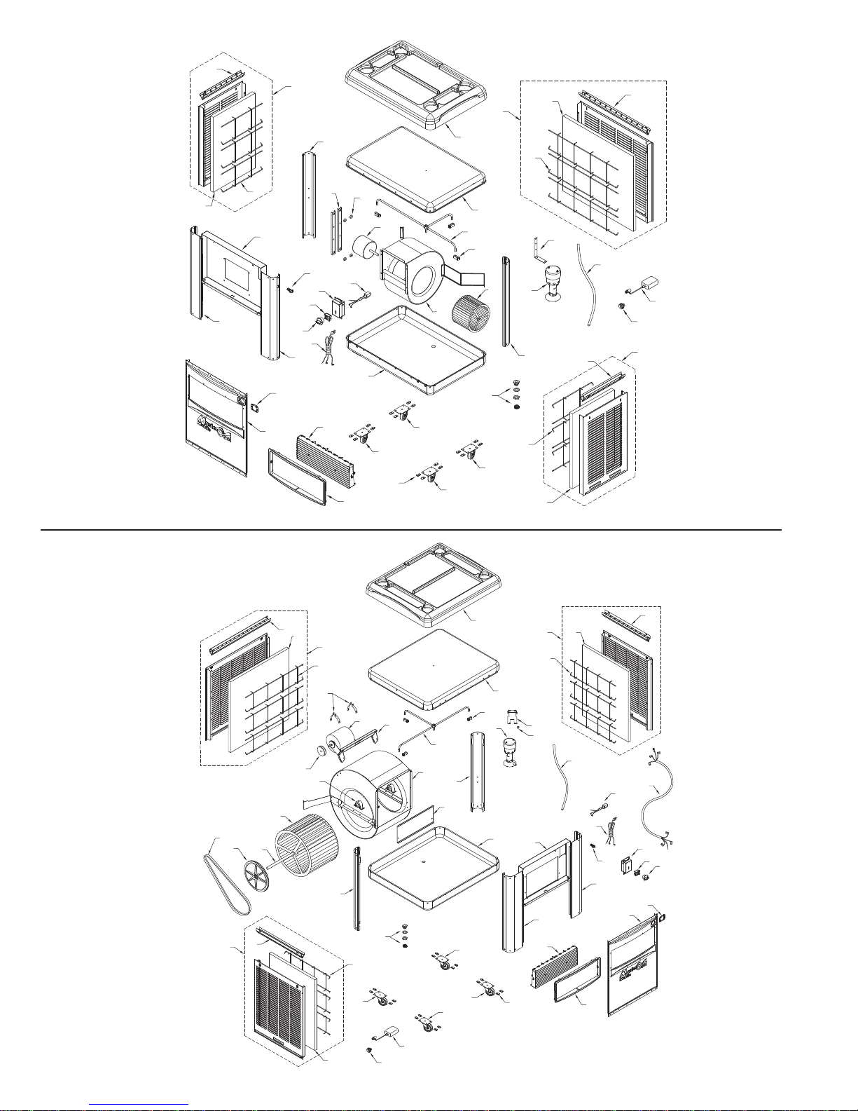
ILLUSTRATED PARTS LIST /
LISTA ILUSTRADA DE PIEZAS DE REPUESTO
(ENGLISH / ESPAÑOL).................................................. 10-11
GARANTIA LIMITADA.......................................................... 12
READ AND SAVE THESE INSTRUCTIONS
1. Read these instructions carefully.
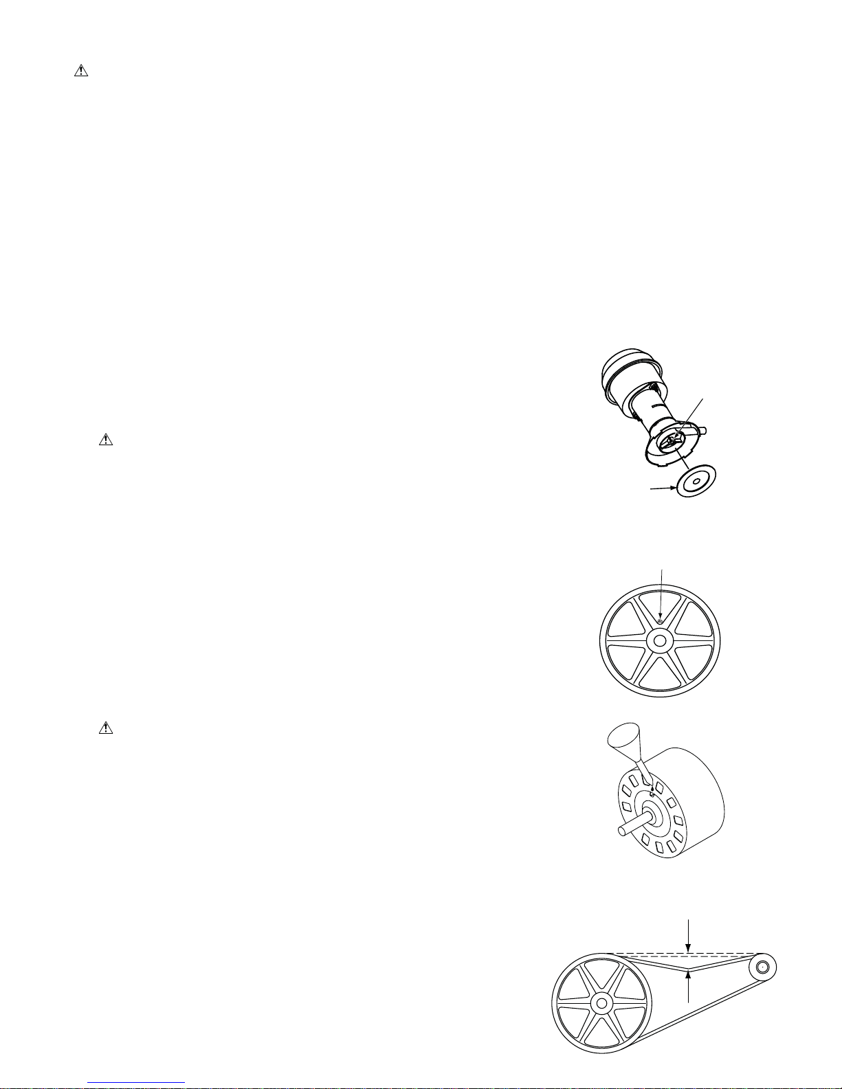
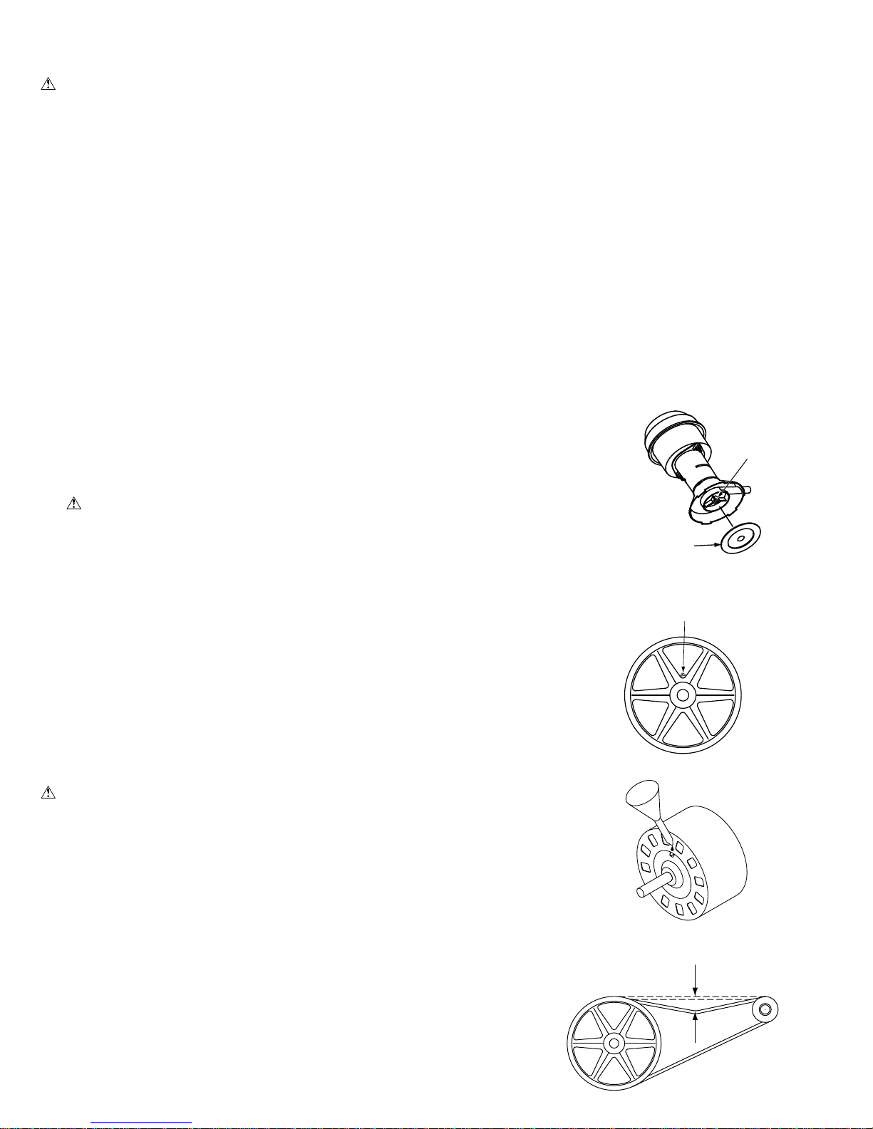
2. Unit must be in the Off Position and Unplugged from power
receptacle when installing or performing any maintenance.
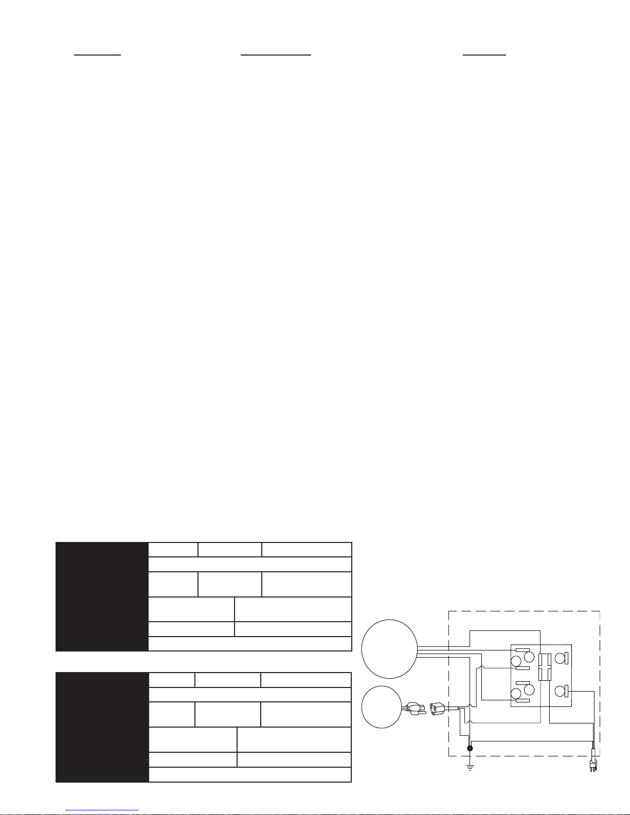
3. This cooler will run on 120 volt A.C., 60 Hz (cycle) current
only.
4. Motor and pump are grounded and have an automatic ther-
mal overload switch which will shut motor off if it overheats.
The motor will restart automatically when it cools down.
5. Pump receptacle is for grounded evaporative cooler pump
only. Do not plug anything else into receptacle.
6. Do Not operate any fan with a damaged cord or plug. Dis-
card fan or return to an authorized service facility for exam-
ination and/or repair.
7
. Do Not run cord under carpeting. Do Not cover cord with throw
rugs, runners or similar coverings. Do Not route cord under
furniture or appliances. Arrange cord away from traffic area
and where it will not be tripped ove
r.
8. Use only in GFCI protected receptacles.
WARNING:To reduce the risk of fire or electric shock,
do not use this fan with any “solid-state fan speed control
device.
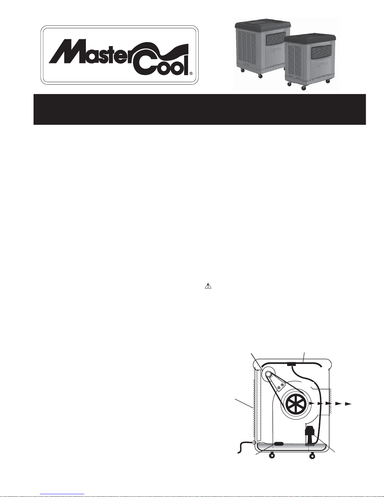
HOW EVAPORATIVE COOLING WORKS
Evaporative cooling is nature’s way of cooling. When air is
moved over a wet surface, water is evaporated and heat is
absorbed. When stepping out of a swimming pool with the wind
blowing, evaporative cooling makes you feel cool, even though
the air may be warm. The human body itself is cooled primarily
by the evaporation of perspiration.
This unit works on the same principle. Air is drawn across
wet filter pads where the air is cooled by evaporation and then
circulated throughout the building. It is this combination of
cooled air and the movement of air over the skin which makes it
feel cool.
Unlike refrigeration systems which recirculate the air, an
evaporative cooler continually brings in fresh air while
exhausting old air. You are completely replacing the air every 2
to 4 minutes by opening windows or doors or a combination of
both. The air is always fresh, not stale, laden with smoke and
odors as happens with refrigerated air conditioning.
WATER
LINE
GRILLE
)
2 SPEED MOTOR WATER DISTRIBUTION HOSE
FLOAT WATER PUMP
WATER-SATURATED
COOLER PADS
3 SIDES
AIR FLOW
BLOWER
PN 110522-3 REV. 11-15