Test
wire
wheel
brush
for
balance
and
loose
or
damaged
wires
by
running
tocl
at
no
load
spd
for
at
least
one
minute
kfore
applying
it
to
your
work.
During
this
time,
no
one
should
stand
in front
of
or
inline
with
it.
When
applying
brush
to
work,
awld
using
too
much
pressure.
This
causes
met-bending
of wires
and
heat
build-up resulting in
premature
wite
breakage,
rapid
dulling
and
reduced
brush
life, Instead
of
using
more
pressure,
try
a
wire
wheel
brush with
more
aggressive
cutting
act~on
(increased
wire
size,
decreased
wire
length or different
brush
type.
E.e.
knot
type
instead
of
crimped
wire
type).
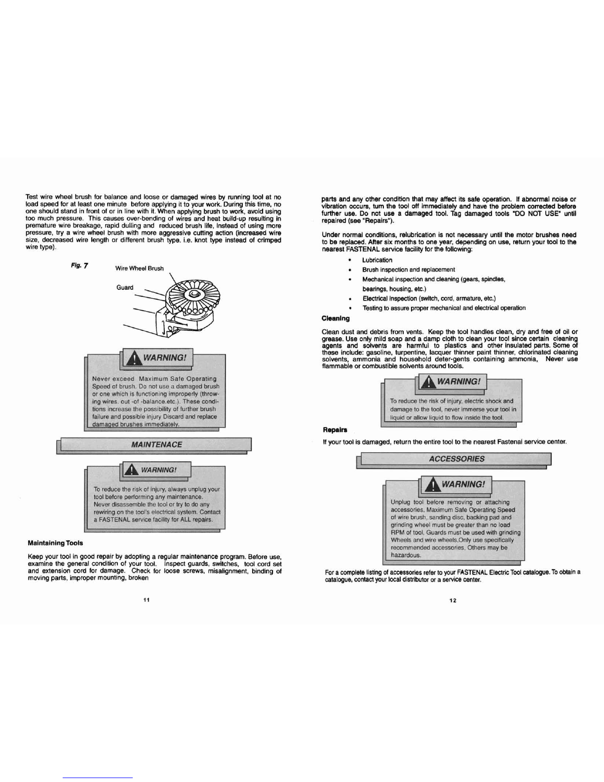
mlm
7
Wire
Wheel
Brush
Never
e:
3fe
Operating
Speed
of
damagedbrush
or
one
whrcn
IS
runcrlonlnglrnproperly
(throw-
ing
wires,
out
-of
-balance.etc.).
These
condi-
t~onsincrease
the
possibility
of
further
brush
failure and
possible
Injury
Discard
and replace
damaqed
brushes immediately.
1
~cceed
ME
brush. Do
..
. .
lr
ALL
repa
-
parts
and
any
otkr
mdMn
that
may
affect
its
aafe
operatiin.
M
abnormal
noisa
w
vibration
occurs,
turn
the
tool
off
immediately
and
hm
the
problem
corrected
before
further
uae.
Do
not
use
a
damaged
tool.
fag
damaged
tmlo
"DO
NQT
USE"
until
repaired
(see
"Repalm").
A
WARNING!
Under
notmar
wndktons,
relubrica#on
is
not
necessary
until
the
Wr
brushes
need
to
be
replaced.
After
six
months
to
one
year,
depending
on
use,
return
your
tool
to
the
nearmt
FASTENAL
service facility
br
the
following:
I
I
To
reduce
the
risk
of
injury,always unptug your
tool
before
pertorrnrng
any
matntenance.
Never
disassemble
the tool or
try
to do
any
rewiringon
the
toof's
electrical
system.
Confacl
a
FASTENAL
servicefacil~ty
fa
is.
1
Lubrication
Brush
inspeetion
anti
replacement
Mdmnical
inspectian
and
cleaning
(gears,
spldbs,
bearings,
housing,
etc.)
Elgctrical
inspection
(switch,
cord,
armature,
ek.)
Testing
to
assure
pmpt
mechanical
and
eteetrtcal
operation
Clean
dust
and
debris
from
wents.
Keep
the
toal
handles
clean,
dr)r
and
free
of
oil
or
grease.
Use
only
mild
soap
and
a
damp cloth
to
clean
your
tool
since
certain
cleaning
agents
and
solvents are
harmful
to
plastics
and
other
insulated
parts.
Some
of
these
include: gasoline, turpentine,
lacquer
thinner
paint
thinner,
chlorinated
cleanlng
solvents, ammonia
and
household
deter-gents
containing
ammonia.
Never
use
flammable
or
combustible solvents aroundtools.
damage
to
the
tool,
never
trnrnerse
your
tool
in
Repairs
If
your
too!
is
damaged,
return
the
entire
tool
to
the
nearest
Fastenal
service
center.
3thers
may
1
I
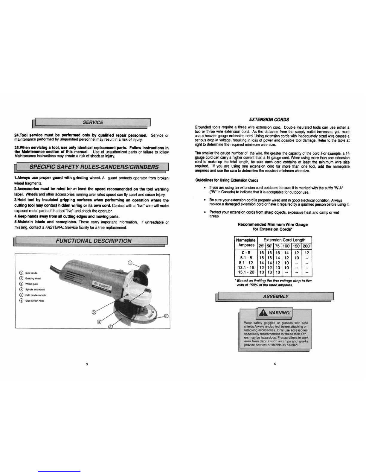
Keep
your
tool
in
good
repair
by
adopting
a
regular
maintenanm
program.
Before
use,
examine
the
general condition
of
your
tool,
Inspect
guards,
switches.
tool
cord
set
and
extension cord
for
damage.
Check
for loose
screws,
misalfgnment,
binding
of
For
a
complete
listing
of
accessories
refer
to
your FASTENALElectricTool
catabgw.
To
obtain
8
moving
parts,
improper mounting,
broken
catalogue,
contact
ywr
local
distributoror
a
sewice
enter.
Unplug
tool
before
removrng
or
attaching
accessories, Max~murn
Sale
Operating
Speed
of
wire
brush,.sand!ng
disc,
backlng
pad
and
grindrng
wheel
must
be
greaterthan no
load
RPM
of
tool,
Guards
must
be
used
w~thgrlnding
1
I
Wheels
and
wlre wheels.Only
use
specifically
recommended
accessor~es.
(
,
be
hazardous.
-
I