Table
Of
Contents
PAGE
1
. SAFETY
SAFETY
RULES
FOR
POWER
TOOLS
.....................
..
..
...
...........................
1
.......................
..........
ADDITIONAL
SAFETY
INSTRUCTlONS
FOR
BUFFERS
..
3
2
.
CIRCUIT
REQUIREMENTS
............
......................
...................................................
120V
OPERATION
..
...
4
.........................
.....................*.....................................
EXTENSION
CORDS
..
4
.........................................................................................................
GROUNDING
5
3
.
INTRODUCTION
........................................................................................................
COMMENTARY
5
....................
UNPACKING
..
............
....
...........................................................
5
..............................
.............*...................................*................*...
MOUNTING
..........
5
4
. OPERATIONS
........................................................
TEST
RUN
....
.............................................
6
........................................................................
GENERAL
....................................
...
6
..........................................................................................
BUFFING&POLTSHING
7
WHEEL
RENOVAL
.................................................................................................
7
.............................................
..........................
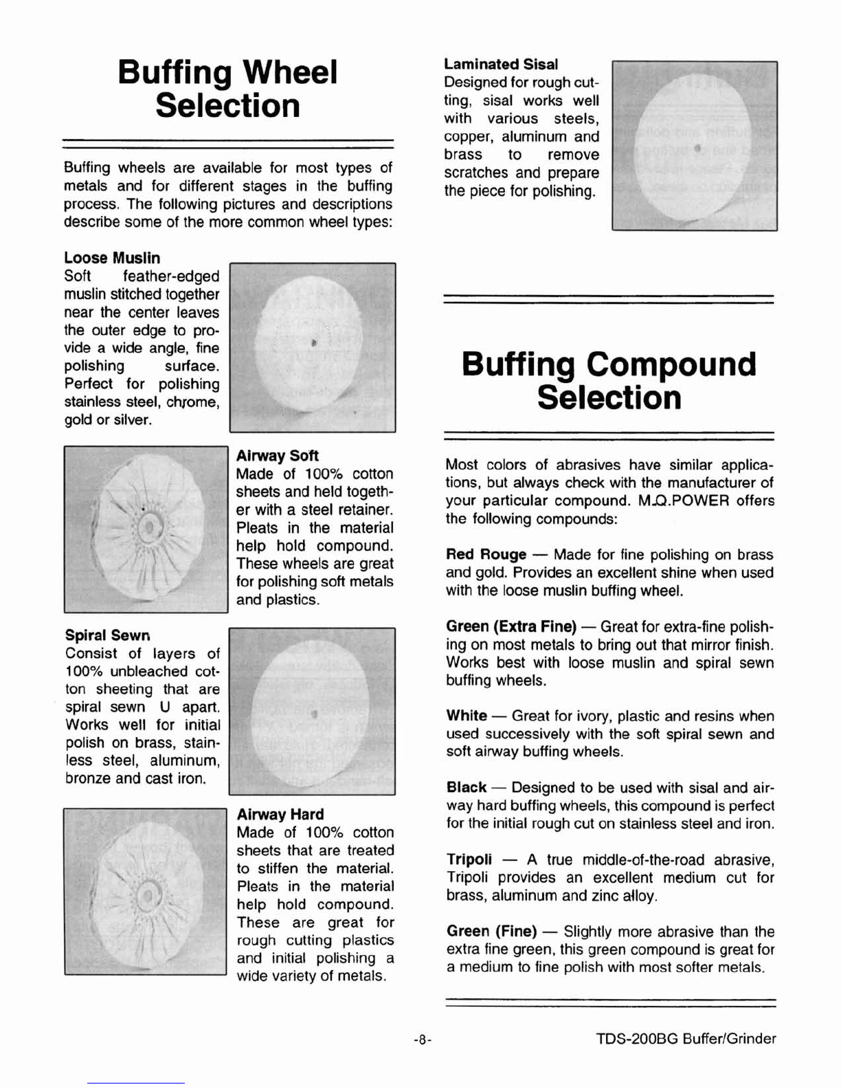
BUFFING
WHEEL
SELECTION
..
8
BUFFING
COMPOUND
SELECTION
...........................
..
......................................
8
.........................................................................................................
8UFFING
TIPS
8
5
.
MAINTENANCE
..........................................................................................................
10
........................................................................
LUBRICAT1ON
.........................
..
10
.......................................................................
MISCELLANEOUS
...................
...
1
0