MasterCraft 068-1577-2 User manual

model no. 068-1577-2
54" (137 cm) Workstation
IMPORTANT
Please read this manual carefully before assembling and
using this product, and save it for reference.
INSTRUCTION
MANUAL
Due to continuing improvements,
the actual product may differ slightly
from the product described herein.

2
TABLE OF CONTENTS
3
3
6
18
19
TABLE OF CONTENTS
SAVE THESE INSTRUCTIONS
This manual contains important safety and operating instructions. Read all
instructions and follow them carefully with use of this product.
NOTE:
If any parts are missing or damaged, or if you have any questions, please call our toll-free
helpline at: 1-800-689-9928. Have the product number, cash register receipt and the date
of purchase available when you call. DO NOT SHIP YOUR PRODUCT BACK TO THE STORE
UNLESS WE SEND YOU WRITTEN INSTRUCTIONS FOR RETURN.
MAINTENANCE
COORDINATING PRODUCTS
WARRANTY
SAFETY
ASSEMBLY INSTRUCTIONS
model no. 068-1577-2 I contact us 1-800-689-9928
4
EXPLODED VIEW
5
PARTS LIST

To reduce the risk of serious injury, read and follow the safety instructions below before assembling
and using this product.
SAFETY
3
SAFETY / MAINTENANCE
Before assembling and using this product, carefully read this instruction manual and all of the labels
affixed to the product. Failure to follow all warnings and instructions may result in product damage or
personal injury.
Save all warnings and instructions for future reference.
-Maximum load: 830 lb (376 kg)
-Maximum load for shelf: 100 lb (45 kg)
-Maximum load for bottom panel: 150 lb (68 kg)
-Maximum load for each drawer: 70 Ib (32 kg)
-Maximum load for rubberwood top: 300 Ib (136 kg)
Keep the product on level surfaces. The product could become unstable and it may tip over if
stored or moved on an uneven surface, which may cause personal injury, death or product damage.
This product is intended for indoor use only.
Use at least two people to move, assemble or install this cabinet. Failure to do so can result in
personal injury or product damage.
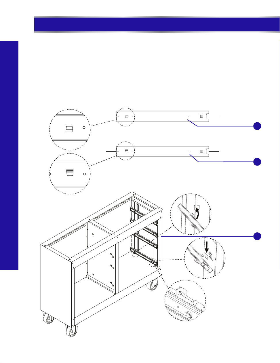
DO NOT open more than one drawer at a time.
Fill from the bottom drawer up. If the cabinet is filled from the top drawer down, it will be top-heavy
and may tip over.
Use the brakes when not moving this product. This will prevent the product from rolling, which may
cause personal injury or product damage.
Close and lock the doors before moving this cabinet.
DO NOT alter this product in any manner. For example, do not weld external bar locks or attach
electrical equipment. This may cause product damage or personal injury.
DO NOT leave children unattended near this product. Cabinets may tip over if improperly opened.
DO NOT exceed the following weight limits for this product.
Lubricate the slides (twice a year) with a spray lubricant or light duty oil.
Periodically clean the surfaces with a soft rag and water.
MAINTENANCE
This product is not designed for commercial nor industrial usage.
For castors, use high quality bearing grease once a year.
Grease and oil can be removed with most standard cleaning fluids. For safety, use a nonflammable
cleaning fluid.
DO NOT step or climb on this product or on the drawers.
It is always recommended to secure this product to the wall with the anti-tip hardware provided.

EXPLODED VIEW
4
model no. 068-1577-2 I contact us 1-800-689-9928
EXPLODED VIEW
1
2
5
4
3
9
20
23 19
8
7
10
16
6
12
13
22
17
21
26
27
28
31
30
34
35
36
15
37
20
38
19
7
1
25 26
8
4
36
23
24
25
32
33
29
11
14
18

PARTS LIST
PARTS LIST
5
No.
12
1
3
524
1
5
7
M6 x 12 hex bolt 41
Description Qty.
No. Description
No. Qty.
20
22
23
25
4
2
1
4
4
6
24
26
11
Shelf
Side handle
1
10
2
12
6
16
27
Front top beam
1
29 2
Part No. Part No.
16
Right slide
Swivel castor
M8 x 25 hex bolt
Washer
Bottom panel
21
Rubber ring
2
30
1
Rigid castor
Right side panel
49
NOTE: Extra pcs are provided.
*
Handle
M6 x 40 hex tapping bolt
M6 x 16 hex socket
head screw *
Drawer panel
168
Middle drawer
front panel
Bottom drawer
front panel
M4 x 6 cross-head pan
head tapping bolt
M4 x 5 cross-head bolt
Top drawer front panel
13
1
16
Right door
4
15
Locking hook
Drawer liner
214
Lock (001-010)
Pin
117
19
Key (001-010)
Left door
28
2
Left slide
31
Centre panel
1
33
Rubberwood top
32
4
Back panel
1
35
34
4
36
1
2
16
1
1
Door stopper
37 1
Shelf bracket
NOTE:
Replacement keys may be ordered. Call our toll-free number. The code which appears on the lock will
be required.
Give information for spare parts: part number and quantity required.
1
18
Magnet
Left side panel
Back top beam
38
Hex wrench
1
321051
306046
121645
320327
242933
242781
320335
320336
300399
121548
121549
121550
302065
552183
304236
236397
118124
306018
237444
314219
118123
203902
121659
321047
324002
302066
121644
312033
236270
300398
121608
113539
121646
572164
320328
242934
317023
304196
*
*
*

STEP 1 ATTACH THE SIDE AND BOTTOM PANELS
ASSEMBLY INSTRUCTIONS
TOOLS REQUIRED FOR ASSEMBLY
• Hex wrench (38)
• Cross-head Screwdriver (not included; magnetic is preferable)
• Measuring Tape (not included)
Please wear gloves during the whole assembly process.
NOTE: Assemble on a flat surface. A piece of cardboard is recommended to keep the product
from being scratched during assembly.
6
model no. 068-1577-2 I contact us 1-800-689-9928
ASSEMBLY INSTRUCTIONS
• Power Drill (not included)
Lay the bottom panel (28) on its front and attach the side panels (3 & 32) to the bottom
panel (28) with two M6 x 16 hex socket head screws (4) through the holes on bottom left
and right corners. D0 NOT tighten.
Back
•
• Screw two M6 x 16 hex socket head screws (4) at the middle of bottom. Tighten securely.
3
28
32
4

STEP 3 ATTACH THE CENTRE PANEL
STEP 2 INSTALL THE CASTORS
NOTE: For easy movement, the swivel casters are suggested to be installed on the same side
as the side handle.
ASSEMBLY INSTRUCTIONS
7
Position the two rigid castors (27) on one side of the bottom of the cabinet. Insert the M8 x 25
hex bolts (25) through washers (26), then through the castors and into the bottom of the cabinet.
Tighten securely.
•
Repeat for the two swivel castors (14) on the other side of the cabinet.
•
Attach the centre panel (34) to the bottom panel (28) with two M6 x 16 hex socket head screws (4).
Tighten securely.
14
25
26
27
34
4
28

STEP 5 ATTACH THE BACK PANELS
STEP 4 ATTACH THE BACK TOP BEAM
8
model no. 068-1577-2 I contact us 1-800-689-9928
ASSEMBLY INSTRUCTIONS
Attach the back panels (33) to the back of the cabinet with twenty-eight M6 x 16 hex socket head
screws (4). Insert the screws by hand. DO NOT tighten.
•
Attach the back top beam (37) to the side panels (3 & 32) with two M6 x 16 hex socket head
screws (4). Insert the screws by hand. DO NOT tighten.
The top edge of the top back panel should be inserted under the back top beam.
4
37
32
3
33
4

123
30
29
STEP 6 ATTACH THE DOOR STOPPER
First press the two trapezoidal tabs at the right side of the front top beam (5) inwards by 90 degrees.
•
Insert the door stopper (30) onto the two tabs. Make sure the magnets (29) are outside of the front
top beam and face toward the front of the cabinet.
•
Finally, bend the two trapezoidal tabs of the front top beam (5) outwards until they are against the
door stopper (30).
•
STEP 7 ATTACH THE FRONT TOP BEAM
Attach the front top beam (5) to the side panels (3 & 32) with six M6 x 16 hex socket head screws (4).
Insert the screws by hand. DO NOT tighten.
•
At the same time, screw four M6 x 16 hex socket head screws (4) through the side panels (3 & 32) to
the bottom panel (28). DO NOT tighten.
•
ASSEMBLY INSTRUCTIONS
9
5
3
5
34
32
28
4

STEP 8 INSTALL THE SLIDES
Front
Front
Back
Back
Left slide
Right slide
31
9
•Slide the back clip of the outer rail of a right slide (9) into the back slot at the right side panel (3) and
slide the front clip of the outer rail into the slot at the front of the right side panel (3).
•Repeat the same procedure to install the other right slides (9) to the right side panel (3).
•Repeat the same procedure to install four left slides (31) to the centre panel (34).
•Bend the eight clips above the left and right slides outwards with the help of a straight screwdriver
so as to secure the slides.
1
3
model no. 068-1577-2 I contact us 1-800-689-9928
ASSEMBLY INSTRUCTIONS
10
3
(back slot)
2(front slot)

STEP 9 ATTACH THE SOLID WOOD TOP AND SECURE TO WALL
•Attach the rubberwood top (35) to the cabinet top by inserting six M6 x 16 hex socket head screws (4)
through the pre-drilled holes underneath. Tighten securely.
•At the same time, square up the cabinet and make sure the inner diagonal lines are equal with the
help of a measuring tape. Tighten all screws on front and back.
•Move the cabinet on a flat floor against a wall. Use a power drill to attach the cabinet to the wall
with two M6 x 40 hex tapping bolts (36) through the holes at the back top beam (37).
Tighten securely. For safety, the bolts shall be drilled into the studs of the wall.
1
STEP 10 ASSEMBLE THE DRAWERS
NOTE: Make sure your platform is free of debris or the drawer bottom is protected before
laying the drawer on its bottom.
Lay the drawer panel (6) on its bottom.
•
•Bend up the side panels upright to 90°. During this process, insert the clips at the two ends
of the back panel into the slots of the side panels.
Bend all the clips towards the back panel until they lean against the back panel.
•
Back
37
36
Wall
Back
ASSEMBLY INSTRUCTIONS
11
4
35

NOTE: At this step, DO NOT use power tool. Otherwise, product damage may be
caused. A magnetic cross-head screwdriver is preferred.
10
7
12
34
STEP 11 ASSEMBLE THE DRAWERS (continued)
•Lay down the drawer front panel (10 & 12 & 13) on its face with a soft mat underneath for
protection.
Put the drawer body's front onto the drawer front panel.
•
Slide the drawer body's front bottom bended edge into the bottom groove of the drawer
front panel.
•
•Turn up the drawer front panel upright to 90°
Fasten the drawer front panel and side panels together by screwing four
M4 x 6 cross-head pan head tapping bolts (7).
•
•Repeat the same procedure to assemble all drawers.
6
1 2 3
4
drawer back
6
model no. 068-1577-2 I contact us 1-800-689-9928
ASSEMBLY INSTRUCTIONS
12

STEP 12 ATTACH THE DRAWERS BOTTOM-UP
Extend the bottom slides and attach the bottom drawer to the slides by sliding the slots at
the drawer's side panels onto the upright clips of the slides.
•
•Secure the drawer to the slides by screwing four M4 x 5 cross-head bolts (8) through the
drawer to the slides.
Repeat the same procedure to attach the other two middle drawers to the slides, attaching
the lower one first.
•
NOTE: Read the procedure to attach the top drawer (refer to page 14) carefully.
Otherwise, product scratch may be caused.
NOTE: At this step, DO NOT use power tool. A magnetic cross-head screwdriver is preferred.
Otherwise, product damage may be caused.
1 2
34
8
ASSEMBLY INSTRUCTIONS
13

Push down – one side
Pull up – other side
Before attaching the top drawer, extend the slides first. There are two black release levers on
each side of inner rails. Pull one up and push the other one down until you see a silver dot.
•
•Repeat the same procedure as the other drawers to attach the top drawer to the slides.
•Place the drawer liners (15) into each drawer of the cabinet.
15
model no. 068-1577-2 I contact us 1-800-689-9928
ASSEMBLY INSTRUCTIONS
14

STEP 13 ATTACH THE DOORS
12 3
•Lay down the left door (22) on its face with a soft mat underneath. Pull the bottom locking tab at
the right bottom corner of the door outwards. Insert a pin (19) through the hole at the door's bottom
corner and put a rubber ring (20) onto the pin's vertical end.
•Repeat the same procedure to install the right door (18).
When pushing the locking tab back to its place, make sure the end of the pin's
horizontal part is inserted into the hole of the locking tab to ensure the pin
is well secured.
19
18
22
View from door bottom
View from door top
locking tab
•Push back the bottom locking tab to its place. Insert the horizontal end of the pin (19) into the hole
at the locking tab at the same time.
•Take up the left door (22) and insert the pin (19) into the hole at the left bottom corner of the bottom
panel (28).
•Pull the upper locking tab at the right top corner of the door outwards. Insert a pin (19) through the
hole at door's right top corner into the hole at the left top corner of the cabinet.
•Push back the upper locking tab to its place. Insert the horizontal end of the pin (19) into the hole at
the locking tab at the same time.
20
ASSEMBLY INSTRUCTIONS
15
28
45

STEP 15 INSTALL THE SHELF
Insert shelf brackets (23) into the slots and place the shelf (24) over the shelf brackets (23).
NOTE: To use the locking mechanism, the shelf must be placed in the re position.cent
24
23
STEP 14 INSTALL THE LOCKING HOOK
Install the lock (16) as shown below, ensuring the lock code stays on top of the lock face. Release
the nut from the lock (16) back and attach the locking hook (17) as shown in illustration 3 below.
Tighten the hook (17) securely with the nut previously removed from the lock (16) back as shown
in illustration 4.
16
3
2
4
This section must be
inserted into the
square hole.
1
17
model no. 068-1577-2 I contact us 1-800-689-9928
ASSEMBLY INSTRUCTIONS
16

STEP 16 INSTALL THE SIDE HANDLE
Simply position the side handle (2) over the holes and attach with four M6 x 12 hex bolts (1).
Tighten securely. The cabinet is ready for use.
DRAWER REMOVAL
DRAWER REPLACEMENT
Extend the drawer slides from the tool chest or cabinet.
Insert the brackets on each side of the drawer into the slots
in the slides, being careful that they are properly positioned.
Once properly inserted, completely close the drawer to set
the slides in their proper positions.
Push down - one side
Pull up - other side
Pull the drawer out until it is extended to the maximum.
There are two black release levers: one on each side of
the drawer. Pull one up while you push the other one
down simultaneously. At the same time, pull the drawer
out of the drawer slides.
1
2
17
ASSEMBLY INSTRUCTIONS

COORDINATING PRODUCTS
This product coordinates well with the units below to offer our best storage solutions. They can be
combined into various combinations to meet different storage requirements.
2-Door Tall Cabinet
068-0006-8
Wall Cabinet
068-0005-0
28" (71 cm) Base Cabinet
068-1554-6
28" (71 cm) Base Cabinet
with Drawers
068-1575-6
54" (137 cm) Workstation
068-1577-2
model no. 068-1577-2 I contact us 1-800-689-9928
18
COORDINATING PRODUCTS
48 x 72" (122 x 183 cm)
Tall Cabinet
068-1576-4

WARRANTY
LIMITED WARRANTY
This product is guaranteed for 1 year from the date of original retail purchase against defects in
materials and workmanship.
Subject to the conditions and limitations described below, this product, if returned to us with a proof
of purchase within the stated warranty period and if covered under this warranty, will be repaired or
replaced (with the same model, or one of equal value or specification), at our option. We will bear
the cost of any repair or replacement and any costs of labour relating thereto.
This warranty is subject to the following conditions and limitations:
A sales receipt that indicates the date of purchase must be provided;
This warranty will not apply to any product or part thereof which is worn or broken or which
has become inoperative due to abuse, misuse, accidental damage, neglect or lack of proper
installation, operation or maintenance (as outlined in the applicable owner's manual or
operating instructions) or which is being used for industrial, professional, commercial or
rental purposes;
This warranty will not apply to normal wear and tear or to expendable parts or accessories
that may be supplied with the product that are expected to become inoperative or unusable
after a reasonable period of use;
This warranty will not apply to routine maintenance and consumable items such as, but not
limited to, fuel, lubricants, vacuum bags, blades, belts, sandpaper, bits, fluids, tune-ups or
adjustments;
(i.e., persons not authorized by the manufacturer);
This warranty will not apply to any product that was sold as a reconditioned or refurbished
product (unless otherwise specified in writing);
This warranty will not apply to any product or part thereof if any part from another
manufacturer is installed therein or any repairs or alterations have been made or attempted
by unauthorized persons;
This warranty will not apply to normal deterioration of the exterior finish, such as, but not
limited to, scratches, dents, paint chips, or to any corrosion or discolouring by heat, abrasive
and chemical cleaners; and
This warranty will not apply to component parts sold by and identified as the product of
another company, which shall be covered under the product manufacturer's warranty, if any.
Additional Limitations
This warranty applies only to the original purchaser and may not be transferred. Neither the retailer
nor the manufacturer shall be liable for any other expense, loss or damage, including, without
limitation, any indirect, incidental, consequential or exemplary damages arising in connection with
the sale, use or inability to use this product.
Notice to Consumer
This product is not guaranteed if used for industrial or commercial purposes.
This warranty gives you specific legal rights, and you may have other rights, which may vary from
province to province. The provisions contained in this warranty are not intended to limit, modify,
take away from, disclaim or exclude any statutory warranties set forth in any applicable provincial
or federal legislation.
Made in China.
Imported by Mastercraft Canada Toronto, Canada M4S 2B8
a)
b)
c)
d)
e)
f)
g)
h)
ti)
This warranty will not apply if damage is caused by repairs made or attempted by others
19
Table of contents