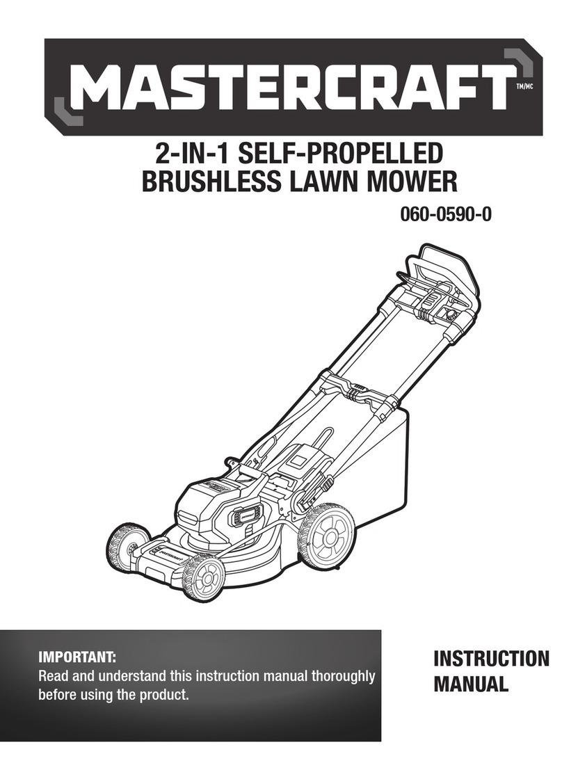
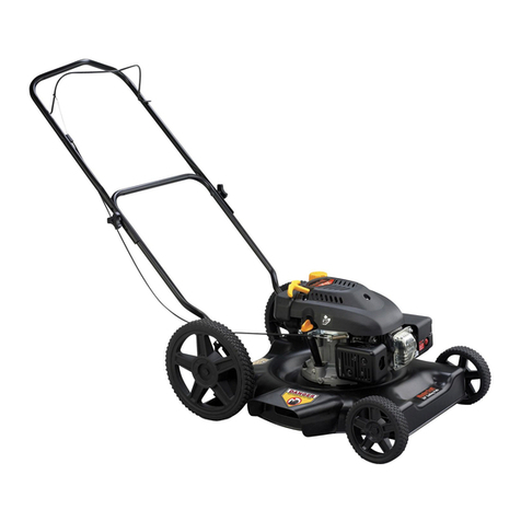
MasterCraft 060-1350-6 User manual

headline bars
continuation tabs
notes
warnings
model no. 060-1350-6
CORDLESS BRUSHLESS
2-IN-1 LAWN MOWER
IMPORTANT :
Read and understand this instruction manual thoroughly
before using the product.
INSTRUCTION
MANUAL

headline bars
continuation tabs
notes
warnings

headline bars
continuation tabs
notes
warnings
3
TABLE OF CONTENTS
Technical Specifications 4
Safety Guidelines 5
Key Parts Diagram 10
Operating Instructions 11
Maintenance 15
Troubleshooting 17
Parts List 18
Warranty 21
NOTE:
If any parts are missing or damaged, or if you have any questions,
please call our toll-free helpline at 1-800-689-9928.
SAVE THESE INSTRUCTIONS
• This manual contains important safety and operating instructions. Read all
instructions and follow them when using this product.
TABLE OF CONTENTS

headline bars
continuation tabs
notes
warnings
model no. 060-1350-6 | contact us 1-800-689-9928
4
TECHNICAL SPECIFICATIONS
Rated Voltage 40 V d.c.
Deck Size 19” (48 cm)
Cutting Height 1 1/2 to 3” (3.8 to 7.6 cm)
*Maximum battery voltage without workload; with workload nominal voltage is 18 V.
Recommend using tool with Mastercraft®20V max* Lithium-Ion 4.0 Ah battery (054-7557-6; sold
separately) for optimal performance.
NOTICE: The mower needs two 20 V max* batteries to work.

headline bars
continuation tabs
notes
warnings
5
SAFETY GUIDELINES:
WARNING!
Safety symbols in this Instruction Manual are used to flag possible dangers. The safety
symbols and their explanations require your full understanding. The safety warnings do not,
by themselves, eliminate any danger, nor are they substitutes for proper accident prevention
measures.
IMPORTANT
This tool should only be serviced by a qualified service technician. For more information, call the
toll-free helpline at 1-800-689-9928. This machine is capable of amputating hands and feet and
throwing objects. Failure to observe the following safety instructions could result in serious injury or
death.
WARNING!
When using electric lawn mowers, basic safety precautions should always be followed to
reduce the risk of fire, electric shock, and personal injury, including the following.
READ ALL INSTRUCTIONS
GENERAL INFORMATION
• Read, understand, and follow instructions and warnings in this manual and on the machine and
attachments.
• Only allow operators who are responsible, trained, familiar with the instructions, and physically
capable to operate the machine.
• Do not operate the machine while under the influence of alcohol or drugs.
PREPARATION BFEORE OPERATING
• Clear the operation area of any objects which could be thrown by or interfere with operation of
the machine.
• Keep the area of operation clear of all bystanders, particularly small children. Stop the machine
and attachment(s) if anyone enters the area.
• Do not operate the machine without the entire grass catcher, discharge chute, or other safety
devices in place and functioning properly. Check frequently for signs of wear or deterioration and
replace as needed.
• Wear appropriate personal protective equipment such as safety glasses, hearing protection, and
footwear.
CHILDREN SPECIFIC
• Tragic accidents can occur if the operator is not alert to the presence of children. Children are
often attracted to the machine and mowing activity. Never assume that children will remain
where you last saw them.
SAFETY GUIDELINES

headline bars
continuation tabs
notes
warnings
6
model no. 060-1350-6 | contact us 1-800-689-9928
• Keep children out of the operating area and under the watchful care of a responsible adult other
than the operator.
OPERATING
• Only operate the machine in daylight or good artificial light.
• Avoid holes, nuts, bumps, rocks, or other hidden hazards. Uneven terrain could overturn
the machine, or cause operator to lose the balance or footing.
• Do not put hands or feet near rotating parts of under the machine. Keep clear of the
discharge opening at all times.
• Do not direct discharge material toward anyone. Avoid discharging material against a wall
or obstruction. Material may ricochet back toward the operator. Stop the blade(s) when crossing
gravel surface.
• Do not mow in reverse unless absolutely necessary. Always look down and behind before
and when backing up.
• Avoid dangerous environment. Don’t use lawn mowers in damp or wet locations.
• Don’t use in rain.
• Keep children away. All visitors should be kept a safe distance from work area.
• Dress properly. Do not wear loose clothing or jewellery. They can be caught in moving parts.
Use of rubber gloves and footwear is recommended when working outdoors.
• Use safety glasses. Always use face or dust mask if operation is dusty.
• Use right appliance. Do not use lawn mower for any job except that for which it is intended.
• Don’t force lawn mower. It will do the job better and safer at the rate for which it was
designed.
• Don’t overreach. Keep proper footing and balance at all times.
• Stay alert. Watch what you are doing. Use common sense. Do not operate lawn mower when
you are tired.
• Store idle lawn mower indoors. When not in use, lawn mower should be stored in an indoor,
dry and locked-up place out of reach of children.
• Maintain lawn mower with care. Keep cutting edges sharp and clean for best and safest
performance. Follow instructions for lubricating and changing accessories. Inspect lawn mower
cord periodically and if damaged, have it repaired by an authorized service facility. Keep handles
dry, clean, and free from oil and grease.
• Keep guards in place and in working order.
• Keep blades sharp.
• Keep hands and feet away from cutting area.
• Objects struck by the lawn mower blade can cause severe injuries to persons. The lawn
should always be carefully examined and cleared of all objects prior to each mowing.
SAFETY GUIDELINES

headline bars
continuation tabs
notes
warnings
7
• If lawn mower strikes a foreign object, follow these steps: 1) Stop lawn mower; release the
switch. 2) Unplug power cord. 3) Inspect for damage. 4) Repair any damage before restarting and
operating the lawn mower.
• Use identical replacement blades only.
• Use extra care while operating machine with grass catcher or other attachment(s).
They can affect the stability of the machine.
SAFETY GUIDELINES FOR BATTERY-OPERATED TOOLS
• Prevent unintentional starting. Ensure the switch is in the off-position before connecting to
battery pack, picking up or carrying the appliance. Carrying the appliance with your finger on the
switch or energizing appliance that have the switch on invites accidents.
• Disconnect the battery pack from the appliance before making any adjustments,
changing accessories, or storing appliance. Such preventive safety measures reduce the
risk of starting the appliance accidentally.
• Recharge only with the charger specified by the manufacturer. A charger that is suitable
for one type of battery pack may create a risk of fire when used with another battery pack.
• Use appliances only with specifically designated battery packs. Use of any other battery
packs may create a risk of injury and fire.
• When battery pack is not in use, keep it away from other metal objects, like paper
clips, coins, keys, nails, screws or other small metal objects, that can make a
connection from one terminal to another. Shorting the battery terminals together may cause
burns or a fire.
• Under abusive conditions, liquid may be ejected from the battery; avoid contact.
If contact accidentally occurs, flush with water. If liquid contacts eyes, seek additional
medical help. Liquid ejected from the battery may cause irritation or burns.
• Do not use a battery pack or appliance that is damaged or modified. Damaged or
modified batteries may exhibit unpredictable behaviour resulting in fire, explosion or risk of injury.
• Do not expose a battery pack or appliance to fire or excessive temperature. Exposure to
fire or temperature above 130°C (265°F) may cause an explosion.
• Follow all charging instructions and do not charge the battery pack or appliance
outside of the temperature range specified in the instructions. Charging improperly or at
temperatures outside of the specified range may damage the battery and increase the risk of fire.
• Have servicing performed by a qualified repair person using only identical replacement
parts. This will ensure that the safety of the product is maintained.
• Do not modify or attempt to repair the appliance or the battery pack (as applicable)
except as indicated in the instructions for use and care.
OPERATION ON A SLOPE
Slopes are a major factor related to slip-and-fall accidents, which can result in severe injury. Operation
on slopes requires extra caution. If you feel uneasy on a slope, do not mow it.
SAFETY GUIDELINES

headline bars
continuation tabs
notes
warnings
8
model no. 060-1350-6 | contact us 1-800-689-9928
• Mow across the face of slopes; never mow up and down. Exercise extreme caution when
changing direction on slopes.
• Watch for holes, ruts, rocks, hidden objects, or bumps which can cause you to slip or trip. Tall
grass can hide obstacles.
• Do not mow near drop-offs, ditches or embankments; you could lose your footing or balance.
• Do not mow slopes greater than 15 degrees. Do not mow on wet grass. Unstable footing could
cause slipping.
• Do not operate machine under any condition where traction, steering, or stability is in question.
Tires could slide even if the wheels are stopped.
• Always keep the machine in gear when going down slopes. Do not coast downhill.
• Avoid starting and stopping on slopes. Avoid making sudden changes in speed or direction. Make
turns slowly and gradually.
ADDITIONAL SAFETY GUIDELINES FOR LAWN MOWER
• The label on your tool may include the following symbols. The symbols and their
definitions are as follows:
V ...................... Volts
A ...................... Amperes
W ..................... Watts
min .................. Minutes
or d.c. .... Direct current
n0 ..................... No-load speed
................. Class II construction
RPM ................. Revolutions per minute
................. WARNING–To reduce the risk of injury, user must read instruction manual.
................. WARNING–To reduce the risk of injury, always wear eye protection.
................. WARNING–To reduce the risk of injury, always wear ear protection.
... Maintain safety devices: Do not open or remove safety shields while the tool is
running.
........... Look behind when backing up. Look down and behind rst to avoid tripping
when pulling back.
KEEP HANDS and FEET AWAY
...... DANGER–Keep hands and feet away. To reduce the risk of injury, keep hands
and feet away from rotating parts. Do not operate unless discharge cover or
grass bag is in its proper place. If damaged, replace immediately.
................ DANGER–Keep bystanders away. Do not mow when children or others are
around.
SAFETY GUIDELINES

headline bars
continuation tabs
notes
warnings
9
SAFETY GUIDELINES
................... DANGER–Thrown debris. Remove objects that can be thrown by the blade in
any direction. Wear safety glasses.
................... DANGER–Steep slope hazard. Use extra caution on slopes.
Do not mow slopes greater than 15 degrees.
WARNING!
To reduce the risk of electric shock or damage to the charger and battery, use only the
Mastercraft®battery and chargers listed.
BATTERY PACK CHARGERS
054-7557-6, 054-7553-4, 054-3124-0 054-3126-6, 054-7559-2
• For best results, your battery and tool should be stored, charged and used in a location
where the temperature is more than 5°C (41°F) but less than 40°C (104°F). Do not store
outside or in vehicles.
• Do not wash the mower with a hose. Avoid getting water in the motor and electrical
connections.
• To reduce a fire hazard, keep the motor cover free of grass, leaves and debris build-up.
SAVE THESE INSTRUCTIONS!

headline bars
continuation tabs
notes
warnings
model no. 060-1350-6 | contact us 1-800-689-9928
10
KEY PARTS DIAGRAM
WARNING!
• Remove the lawn mower from the package and examine it carefully. Do not discard the carton or any packaging material until
all parts have been examined.
• If any part of the lawn mower is missing or damaged, do not attach the battery pack to the tool or use the tool until the part
has been repaired or replaced. Failure to heed this warning could result in serious injury.
• Do not allow familiarity with the lawn mower to cause a lack of alertness. A fraction of a second of carelessness is enough to
cause severe injury.
FPO
PACKAGE CONTENTS:
Cordless lawn mower, (2) cable clamps, grass collection bag, (2) bolts, (2) knobs, (2) locking levers,
(2) washers, (2) nuts, upper handle bar, lower handle bar, mulching insert (inside of the mower).
KEY PARTS DIAGRAM
3
1
4
6
9
8
5
2
10
7
No. Description No. Description
1 Start lever 6 Cutting-height-adjustment lever
2 Upper handle bar 7 Knob
3 Safety lock-off switch 8 Battery compartment
4 Grass collection bag 9 Rear-discharge door
5 Locking lever 10 Lower handle bar
Before attempting to use this tool, become familiar with all of its operating features and safety
requirements. For optimum performance and safety, read the following operating instructions carefully
before using.

headline bars
continuation tabs
notes
warnings
11
OPERATING INSTRUCTIONS
ASSEMBLE THE LOWER HANDLE BAR
1. Align one hole of the lower handle bar with the
rib on the mower, attach the lower handle bar
onto the rib, and then align the other side of the
lower handle bar to attach the bar onto the other
rib (fig 1a). It’s recommended to use a flat-head
screwdriver to assemble the lower handle bar.
2. Make the raised foam portion of the lower handle
bar face upwards, otherwise you will have less
space to attach or remove the grass collection bag
(fig 1b). The insert picture shows the outline when
looking at the back of the lower handle bar.
3. Insert the bolts into the square holes as shown in
fig 1c and then turn the knobs clockwise to lock
the lower handle bar onto the mower.
fig 1a
Hole
Rib
fig 1c
Bolt Knob
NOTICE:
• The bolt with the square head should be fully inserted into the square hole on the mower.
• If you couldn’t fully tighten the upper handle bar, you should further turn the locking levers clockwise.
Lower handle
bar
fig 1b
Hole

headline bars
continuation tabs
notes
warnings
12
model no. 060-1350-6 | contact us 1-800-689-9928
ASSEMBLE THE UPPER HANDLE BAR
(fig 2)
1. Align the holes on the upper handle bar with the
holes on the lower handle bar.
2. Insert the locking levers with washers into the
holes and nuts and then turn the locking levers
clockwise to lock the upper handle bar onto the
lower handle bar.
CABLE CLAMP
(fig 3)
This mower is equipped with two cable clamps.
Simply press the cable clamps onto the bar, and then
the cable can be xed onto the upper handle bar.
ATTACH/REMOVE THE MULCHING INSERT
(fig 4)
1. Lift the rear-discharge door and insert the mulching
insert into the grass outlet of the mower. And then
release the rear-discharge door.
2. To remove it, lift the rear-discharge door and just
pull the mulching insert out directly. Then release
the rear-discharge door.
OPERATING INSTRUCTIONS
NOTICE:
• The mulching insert must be removed in order to install and use the grass collection bag.
• When using the function of the mulching insert, you can get more fine grass clippings on your lawn.
• Empty the grass collection bag frequently during use. Do not wait until it is completely full. We recommend emptying it when
it is half full.
fig 4 Rear-discharge
door
Mulching
insert
fig 3
Cable
clamps
fig 2 Upper handle bar
Nut
Washer
Locking
lever Lower handle bar

headline bars
continuation tabs
notes
warnings
13
ATTACH/REMOVE THE GRASS
COLLECTION BAG
(fig 5)
1. Remove the pre-installed mulching insert before
attaching the grass collection bag to the mower.
2. Use one hand to lift the rear-discharge door; use
your other hand to hold the handle bar of the grass
collection bag, and align the rods on the grass
collection bag with the slots on the mower to
assemble it.
3. To remove the grass collection bag, just lift the
rear-discharge door and remove the rods of grass
collection bag.
ADJUST THE CUTTING HEIGHT
(fig 6)
Pull out the cutting-height-adjustment lever from the
slot, then move it forward or backward to adjust the
cutting height
(fig 6a)
. The mower has five slots which
can adjust the cutting height from about
1 1/2 to 3” (3.8 to 7.6 cm). Do not place the lever out of
the five slots
(fig 6b)
.
TO ATTACH THE BATTERY
(fig 7)
1. Open the protective cap of the battery
compartment.
2. Align the raised portion on the battery pack with
the grooves inside of the battery compartment, and
then slide the battery pack onto the mower.
3. Ensure that the battery-release button on the
battery pack snaps into place and the battery pack
is secured to the tool before beginning operation.
OPERATING INSTRUCTIONS
fig 5
Rear-discharge
door
Grass collection bag
Handle bar
1
2 2
fig 6a Cutting-height-
adjustment lever
X
X
fig 6b
WARNING!
• Keep your feet away from the deck when adjusting its height.
• To avoid the possibility of accidental starting, always take care not to activate the start lever when you are
attaching the battery pack or performing other adjustments to the tool.
FPO
NOTICE: Two batteries should be used together to start the mower. The mower cannot be used with only
one battery.

headline bars
continuation tabs
notes
warnings
headline bars
continuation tabs
notes
warnings
14
model no. 060-1350-6 | contact us 1-800-689-9928
TO DETACH THE BATTERY
(fig 7)
1. Open the protective cap of the battery
compartment.
2. Depress the battery-release button located on the
front of the battery pack to release the battery.
3. Pull rearward on the battery pack to remove it from
the tool.
SAFETY KEY
(fig 8)
In order to prevent accidental start-up or
unauthorized use of your cordless mower, a
removable safety key has been incorporated into the
design of your mower.
The mower will be completely disabled when the
safety key has been removed from the mower. Press
the lever, insert the safety key into the assembly slot,
and then the mower may be operated.
START/STOP THE MOWER
(fig 9)
1. Install the battery packs into the mower, insert
the safety key into the key slot and then close the
battery compartment.
2. Depress the safety lock-off switch first, pull back
the start lever to meet the handle and then release
the safety lock-off switch to start the machine.
3. To stop, fully release the start lever. The electric
brake will stop the blade rotation within several
seconds after releasing the start lever.
OPERATING INSTRUCTIONS
WARNING!
• Rotating blades can cause serious injury. To prevent serious injury, remove the safety key when the mower is unattended, or
when adjusting, cleaning, servicing, transporting, lifting, or storing the mower.
• The operation of any lawn mower can result in foreign objects being thrown into your or others’ eyes, which can damage eyes
severely. Always wear safety glasses while operating the mower or while performing any adjustments or repairs on the mower.
• Ensure that other people and pets remain at least 100’ (30 m) away from the mower when it is in use.
• The blade will continue to rotate for a few seconds after the mower is turned off. Allow the motor/blade to stop rotating before
starting it again. Do not rapidly turn the mower off and on.
FPO
fig 9 Start lever
Safety
lock-off
switch
fig 8 Lever Sefety key
fig 7 Battery-release
button
Protective
cap

headline bars
continuation tabs
notes
warnings
15
headline bars
continuation tabs
notes
warnings
MAINTENANCE
MAINTENANCE
REMOVE/INSTALL THE BLADE
(fig 10)
After prolonged use, especially in sandy soil
conditions, the blade will become worn and lose
some of the original shape, which will reduce the
cutting efficiency. Therefore, the blade should be
replaced to ensure a good cutting performance.
1. Remove the safety key and battery pack.
2. Turn the mower upside down. Keep the underbody
and blade clean and free of debris.
3. Use a piece of wood to keep the blade from
turning, loosen the hex bolt counter-clockwise
using a suitable wrench and remove it together
with the blade.
4. Attach a new blade of the same type onto the
spindle while maintaining the correct alignment.
Insert the hex bolt on the spindle. Use a piece of
wood to keep the blade from turning, and then
tighten the hex bolt clockwise to ensure safe
operation of your product.
CLEAN THE MOWER
The underside of mower deck should be cleaned after each use as grass clippings, leaves, dirt and
other debris will accumulate. This accumulation is undesirable, and it will promote rust and corrosion
on metal parts and reduce the cutting efficiency of the mower. Wipe the mower clean with a damp
cloth.
fig 10b
fig 10a Bolt
Blade
Fan

headline bars
continuation tabs
notes
warnings
headline bars
continuation tabs
notes
warnings
16
model no. 060-1350-6 | contact us 1-800-689-9928
STORAGE
(fig 11)
1. Switch the product off and remove the safety key
and battery packs.
2. Store the product and its accessories in a dark, dry,
frost-free, and well-ventilated place.
3. Always store the product in a place that is
inaccessible to children.
4. Do not store it next to corrosive materials, such as
fertilizer or rock salt.
5. The mower can be stored in a compact way. Pull
out and press locking levers (fig 11a) to the
position as shown in fig 11b, and then you can fold
the upper handle bar into the storage position
(fig 11c).
To unfold and use the mower, simply lift the locking
lever to the locked position as shown in fig 11a.
CARRY THE MOWER
(fig 11c)
After folding the mower, it can be carried using
the lower handle and the handle on the battery
compartment together, as shown in fig 11c. DO
NOT attempt to lift the mower by grasping the upper
handle bar.
MAINTENANCE
WARNING!
• Wear safety gloves when working on the blade and close to it. Use proper tools to remove debris, i.e., a wooden stick. Never
use your bare hands.
• Do not let brake fluids, gasoline, petroleum-based products, penetrating oil, etc., come into contact with plastic parts. These
substances contain chemicals that can damage, weaken, or destroy plastic.
• When servicing, use only identical replacement parts. The use of any other parts may create a hazard or cause damage to the
product.
• Always remove the safety key and battery pack when servicing or transporting the mower.
• To ensure safety and reliability, all repairs should be performed by a qualified service technician.
FPO
fig 11b
fig 11a
Locking
lever
fig 11c Lower handle
Handle

headline bars
continuation tabs
notes
warnings
17
headline bars
continuation tabs
notes
warnings
TROUBLESHOOTING
TROUBLESHOOTING
Problem Possible causes Solutions
The mower doesn’t
work.
The battery is depleted. Charge the battery pack.
The motor or the battery is over-
loaded.
Raise the cutting height, and restart
the tool again.
The battery or the tool is too hot. Wait for the battery or tool to cool
down, and then start the tool again.
The safety key is not inserted into the
slot of the battery compartment. Insert the safety key into the slot.
Mower runs but cutting
performance is unsat-
isfactory.
Blade is dull. Keep the blade sharp.
Deck or discharge chute is clogging. Clean the deck or discharge chute.
Mower is abnormally
noisy and vibrates. The blade is bent or damaged. Replace with a new blade.
Grass collection bag
doesn’t pick up grass
clippings.
Discharge chute is clogged. Clear the grass clippings in the
discharge chute.
Bag is full. Empty the bag more often.
If the problem remains unsolved after performing the checks described above, call the toll-free helpline
at 1-800-689-9928.

headline bars
continuation tabs
notes
warnings
headline bars
continuation tabs
notes
warnings
model no. 060-1350-6 | contact us 1-800-689-9928
18
EXPLODED VIEW
PARTS LIST

headline bars
continuation tabs
notes
warnings
19
headline bars
continuation tabs
notes
warnings
No. Part no. Description No. Part no. Description
1 0601350601 Blade Bolt 33 0601350633 Plate
2 0601350602 Blade 34 0601350634 Grass Guide Plate
3 0601350603 Fan 35 0601350635 Front Face
4 0601350604 Power Head 36 0601350636 Square Head Bolt
5 0601350605 Right Front Wheel Cover 37 0601350637 Hexagonal Nut
6 0601350606 Right Front Wheel 38 0601350638 Back Cover
7 0601350607 Square Head Bolt 39 0601350639 Dust Strip
8 0601350608 Front Wheel Bracket 40 0601350640 Torsion Spring
9 0601350609 Front Wheel Axle 41 0601350641 Pin
10 0601350610 Front Wheel Bracket 42 0601350642 Bolt
11 0601350611 Wave Washer 43 0601350643 Bracket
12 0601350612 Hexagonal Nut 44 0601350644 Bracket
13 0601350613 Left Front Wheel 45 0601350645 Right Rear Wheel Cover
14 0601350614 Flange Nut 46 0601350646 Right Wheel
15 0601350615 Left Front Wheel Cover 47 0601350647 Rear Wheel Cover
16 0601350616 Screw 48 0601350648 Screw
17 0601350617 Torsion Spring Seat 49 0601350649 Bearing Housing
18 0601350618 Shaft 50 0601350650 Nut
19 0601350619 Assembly 51 0601350651 Rear Axle
20 0601350620 Hexagonal Nut 52 0601350652 Flat Washer
21 0601350621 Right Height Handle 53 0601350653 Rear Left Wheel
22 0601350622 Left Height Handle 54 0601350654 Rear Left Wheel Cover
23 0601350623 Screw 55 0601350655 Grass Bag Bracket
24 0601350624 Base 56 0601350656 Grass Bag
25 0601350625 Screw 57 0601350657 Lever
26 0601350626 Nut 58 0601350658 Cylindrical Pin
27 0601350627 Tension Spring 59 0601350659 Bolt
28 0601350628 Connecting Rod 60 0601350660 Nut Bracket
29 0601350629 Torsion Spring 61 0601350661 Hexagonal Nut
30 0601350630 E-Ring Circlip 62 0601350662 Flat Washer
31 0601350631 Flat Washer 63 0601350663 Square Head Bolt
32 0601350632 Mulching Insert 64 0601350664 Lower Handle Bar
PARTS LIST

headline bars
continuation tabs
notes
warnings
headline bars
continuation tabs
notes
warnings
20
model no. 060-1350-6 | contact us 1-800-689-9928
65 0601350665 Knob 79 0601350679 Switch Cover
66 0601350666 Protective Hose 80 0601350680 Rubber Hose
67 0601350667 Cable Clamp 81 0601350681 Upper Handle Bar
68 0601350668 Terminal Sleeve 82 0601350682 Wire Trigger
69 0601350669 Switch Box 83 0601350683 Trigger Seat
70 0601350670 Elastic Sheet 84 0601350684 Reset Torsion Spring
71 0601350671 Button 85 0601350685 Trigger Cover
72 0601350672 Trigger Block 86 0601350686 Round Cover
73 0601350673 Rocket Switch 87 0601350687 Square Cover
74 0601350674 Power Cord 88 0601350688 Square Screw Cap
75 0601350675 Trigger 89 0601350689 Screw
76 0601350676 Switch Spring 90 0601350690 Protective Cover
77 0601350677 Cable Press Plate 91 0601350691 Press Plate
78 0601350678 Switch Cover 92 0601350692 Screw
If any parts are missing or damaged, or if you have any questions, please call the toll-free helpline at
1-800-689-9928.
PARTS LIST
Table of contents
Other MasterCraft Lawn Mower manuals