MasterSounds Two Valve MK2 User manual

Two Va l ve
MK2
FOR MUSIC LOVERS, BY MUSIC LOVERS.

WELCOME TO THE FAMILY
Welcome to the MasterSounds Valve range of
rotary DJ mixers.
Building on the success of the award-winning Radius DJ
mixers, the new MasterSounds flagship Valve range
comprises of premium 2/4 channel boutique DJ mixers
aimed at clubs and DJs requiring a conventional DJ
toolkit with a “no compromise” approach to
audio fidelity.
Valve, on another level.
Built for discerning DJs.
Support Socials
If you experience any issues, please
contact us immediately - scan the
QR codes below for our support and,
social channels.

WHAT'S IN THE BOXIMPORTANT SAFETY INSTRUCTIONS
READ THE INSTRUCTIONS Read and retain these instructions for future
reference. Adhere to all warnings printed here and on the console and its
power unit.
COVERS Do not remove the power unit cover. Operate the console with its
cover correctly fitted. Refer servicing work to authorised personnel only.
MAINS POWER Connect the console power unit to a mains power supply only of
the type described in this user guide and marked on the unit. The power source
must provide a good ground connection. Do not remove or tamper with the ground
connection in the power cord. Use the power cord with a sealed mains plug
appropriate for your local mains supply as provided with the console. Route
the power cord so that it is not likely to be walked on, stretched or pinched
by items placed upon or against it. MasterSounds recommends the use of a mains
conditioner on all our DJ mixers.
INSTALLATION Install the console and its power unit in accordance with the
instructions printed in this user guide. Do not connect the output of power
amplifiers directly to the console. Use audio connectors and plugs only for
their intended purpose.
VENTILATION Ensure adequate ventilation around the console and its power
unit. Do not obstruct the ventilation slots or position the unit where the
airflow required for ventilation is impeded.
MOISTURE To reduce the risk of fire or electric shock do not expose the
equipment to rain or moisture or use it in damp or wet conditions. Do not
place containers of liquids on it, which might spill into any openings.
ENVIRONMENT Locate the units away from direct sunlight and any equipment
which produces heat, such as power supplies, amplifiers, and heaters. Protect
from excessive dirt, dust, heat, and vibration when operating and storing.
Avoid tobacco ash, drinks spillage, and smoke, especially that associated with
smoke machines. Do not mount the power supply on any surface subject to
resonance or vibration.
HANDLING To prevent damage to the controls and cosmetics avoid placing heavy
objects on the console surfaces, scratching the surface with sharp objects, or
rough handling and vibration. Protect the controls from damage during transit.
Use adequate packing if you need to ship the unit.
1x Mixer
1x Power Supply
1x Mains Cable (UK/EU/USA)
1x Warnings Booklet
1x Keep on Grooovin’ Postcard

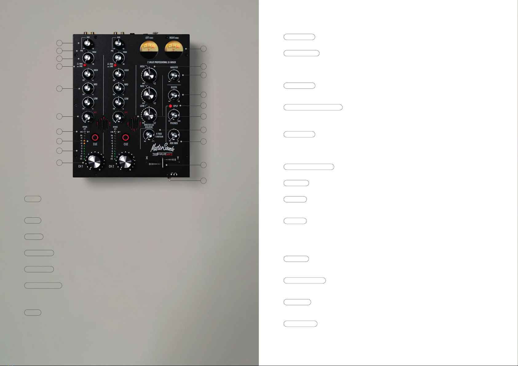
8- VALVE SLOT There are 2 VALVE SLOTS on the front panel, with an attractive perforated mesh
below each slot arrangement. Above image shows the valve, with a subtle red LED glow around it.
9- XFADE SWITCH Below each CUE button is an XFADE toggle switch. This switch assigns the
crossfader to the desired channel. If the XFADE toggle switch is set to X the channel mix is sent
via the crossfader and sound will be heard if the crossfader is set to X. When the OFF toggle is
selected sound bypasses the crossfader, and when the toggle switch is set to Y no sound will be
heard in the mix if the crossfader is set to X.
10- LED METER Each of the 2 channels features a 10-bar LED meter. This visually shows the amount
of input signal being processed through each channel, ranging from -25dB to PK (PEAK SIGNAL). The
normal operating range should be -6dB to +6dB with an average of 0dB.
11- CH1 & CH2 ROTARY FADER Each channel has a large ROTARY FADER for precision control of its
level when mixing. The rotary ranges from fully off when anti-clockwise to unity gain (0dB) when
clockwise. For best performance operate these controls near to their fully clockwise position for
normal music level.
12- VU METERS TWO VALVE MK2 features two high-quality analogue VU (Volume Unit) meters, which
accurately measure the left and right audio signals. The meters show the post-EQ sound level. An
added feature of the VU Meters is that when driven over +6VU the meter will illuminate RED to warn
against clipping. In SPLIT MODE the LEFT VU Meter indicates the cue signal level, and the RIGHT VU
Meter indicates the MIX level, (see SPLIT below).
13- MASTER EQ/ISOLATOR The MASTER EQ/ISOLATOR functions as a normal isolator using 12dB/octave
filters, with crossover frequencies at 350Hz and 3.5kHz making for a very musical isolator.
14- MASTER The MASTER rotary pot adjusts the signal level sent to the Main Output XLRs (House
Mix) ranging from off to +10dBu of gain. Set the control to approximately 1 o’clock for unity gain.
15- BOOTH The BOOTH rotary pot adjusts the signal level sent to the Booth Output TRS Jacks
(Monitor Mix) ranging from off to +10dBu of gain. Set the control to approximately 1 o’clock for
unity gain.
16- SPLIT The SPLIT CUE button illuminates RED when activated and links to the CUE buttons and VU
Meters. When the SPLIT CUE is active and a channel CUE is pressed, the mix buss level will be
shown on the right meter, and the channel pre-fade signal (CUE) will be shown on the left meter,
enabling you to balance the two levels. The Split button also sends the cued source to the Left
headphone and the mix source to the Right headphone. SPLIT CUE is automatically disabled when the
Channel CUEs are off, and the Meters and Headphones revert to monitoring the stereo master signal.
17- PHONES Please take care when monitoring with headphones as excessive sound volumes can cause
premature deafness. The ¼” jack headphone input is located on the front of the mixer as shown on
the headphone graphic.
18- X FADE CONTOUR When the pot is turned fully anti-clockwise, the crossfader slope is very
mild, great for blending tracks. Rotate the pot clockwise and you will hear the crossfader slope
sharpen up. Fully rotate the pot clockwise for ultra-sharp cuts when scratching.
19- ADD MIX The add mix knob controls the amount of stereo house mix sent to your cued track in
the headphones. When the knob is rotated fully anti-clockwise only the cued track will be heard.
Turning the knob clockwise increases the amount of house mix that can be heard in the headphones.
20- CROSSFADER The crossfader enables you to mix between signals assigned to X or Y as indicated
in the screen-printed text. The crossfader enables a variety of DJ styles to be performed, from a
basic fade, to smooth beat matching and complex scratch maneuvers. Use the crossfader with the
XFADE SWITCH (SEE ABOVE) to select which channels to assign to the X or Y position.
FRONT PANEL CONTROLS FRONT PANEL CONTROLS
1- AUX The AUX send level pot adjusts the amount of channel signal level sent to the aux mix buss
(and onto an external FX unit). Fully clockwise the signal level is boosted by +10dBu, allowing for
precise adjustment of FX signals.
2- PRE The PRE button switches the AUX to send a feed from post-fader to pre-fader (i.e. set to
pre-fader it will still send to the aux mix buss with the rotary fader down).
3- TRIM The TRIM pot adjusts the input signal level from OFF up to a maximum of +10dBu, enabling
accurate level matching between different musical sources.
4- LINE/RIAA This button selects either the RIAA (Phono) level input in its top position, or the
LINE input in the bottom position as indicated with screen-printed text.
5- 3 BAND EQ TWO VALVE MK2 features a traditional HIGH MID LOW equalisation system, each pot
gives -20dB of cut and +6dB of boost per band, with channel frequency at 150Hz, 1kHz, 2kHz.
6- VARIABLEQ HPF The new Variable-Q filter provides a natural roll-off at low frequencies, lending
perfectly to mixing with filters alone, but as the knob is rotated the Q automatically rises to
provide that classic analogue swept filter sound, with a high-pass filter frequency range of 18Hz –
1.8kHz.
7- CUE Each CUE button routes the channel signal to the headphones. Pressing the CUE button
illuminates the red LED. When CUE buttons are activated you can hear the selected CUE channels
playing. When no CUE button is active the headphone signal is automatically routed to the master
mix buss.
1
2
3
4
5
6
9
7
10
11
8
12
13
15
16
19
20
17
18
14

REAR PANEL CONTROLS USING THE EXTERNAL SEND & RETURN SYSTEM
1- MASTER OUT Output level is +14dBu when the MASTER level control is fully clockwise and the VU
meters read -4VU. The XLR output is designed to operate with balanced equipment such as powered
monitor speakers and amplifiers.
2- AUX SEND & RETURN/INSERT The AUX SEND & AUX RETURN system has ¼” TRS (balanced) jack sockets
for connection to an external FX unit. The SEND is connected to the FX units’ input, and the FX
units’ output is connected to the RETURN, (see USING THE EXTERNAL SEND & RETURN SYSTEM).
3- INSERT ON BUTTON Reconfigures the aux return jacks as a mix buss Insert, giving the user
unparalleled flexibility for FX integration at the press of a button (see USING THE EXTERNAL SEND &
RETURN SYSTEM).
4- GROUND POST Unscrew the knurled nut, attach the turntable(s) ground lead(s), and screw back
into place without over-tightening the nut.
5- RECORD OUT Twin RCA sockets enable the user to make a stereo recording of a performance. The
overall volume of the master output does not affect the record-out function—this outputs at -6dBu.
6- BOOTH OUT The ¼” TRS (balanced) jack booth output feeds the DJ’s booth (local monitor)
amplifier/loudspeaker system.
7- POWER SWITCH “O” = OFF. Press the “–“ to power the mixer ON with the external power supply
connected.
8- POWER INPUT SOCKET Connect the external 18V power supply to the input socket as labeled on the
rear panel. The power input socket has a twist & lock mechanism for use with our LinearPOWER supply
upgrade.
9- CH ONE & CH TWO Both CH1 & CH2 feature LINE & PHONO inputs which have twin (left & right) RCA
phono sockets. The Phono Input provides gain and RIAA equalization for turntable cartridges, and
the LINE inputs provide input for CD players.
STEP 1 Connect the Mixer Aux Send outputs to the FX unit inputs and connect
the FX unit’s outputs to the mixer Aux Returns. Set the FX unit to unity gain.
STEP 2 Turning up the mixer channel send control feeds the channel signal to
the FX unit. This signal is processed by the FX unit and its output is fed
back into the mix, adding an echo, delay, reverb, or other effect to the
track that’s playing. Turning down the mixer channel send stops the channel
signal feeding to the FX unit and so also stops the effect. Turning up the
mixer channel send increases the level of FX.
STEP 3 Normally the feed to the channel AUX send is also controlled by the
channel fader, so turning down the fader also turns down the level of FX.
However if the AUX send PRE button is pressed, the AUX send takes its signal
before the Channel Fader so the channel signal can be sent to the FX Unit even
if the fader is off. This can be a cool way to mix into a new track:
introducing a low level delay of the track you are about to mix into, before
mixing in the new track by bringing up the channel fader.
STEP 4 MIX INSERT – MasterSounds DJ mixers have a unique feature that allows
the aux return jack sockets to be reconfigured as a mix buss Insert point, just
by pressing the INSERT ON button. This allows you to run the entire mix
through an external FX processor or other devices, such as a compressor,
limiter, or graphic equaliser. With the button pressed the two ¼” TRS Jacks
become a conventional mixer Insert, with the Tip being the SEND, and the Ring
being the RETURN.
9
4 6
1
2
3
578

TECHNICAL SPECIFICATIONS
POWER REQUIREMENT
(Each mixer is supplied with a compact switch-mode power supply for anywhere
in the world and we supply the correct IEC lead for your country)
External Power Supply - Universal 90V – 265V AC 50/60Hz 18v 30W Max
DC Internal Power Rails - +/- 18V DC
AUDIO PERFORMANCE
THD+N OdBu Line In to Mix Out: 0.05%
+10dBu Line in to Mix Out: 0.1% Frequency Response 20Hz to 120kHz: +1/-2dB
Noise unity Line In to Mix Out: -88dBu unweighted.
Residual Mix Noise: -110dBu unweighted.
High-Pass Filter frequency range: 18Hz – 1.8kHz
Dynamic Range - >116dB
Maximum Signal Level - ±27dBu
Headphone Output Power - 800mW RMS into 32 Ohms
EQ/FILTERS
Channel EQ - 3 Band -20/+6dB
Channel EQ Frequency - 150Hz, 1kHz, 2kHz
Master EQ/Isolator Cut/Boost - OFF to +12dB
Master EQ/Isolator Crossover Fc - 350Hz and 3.5kHz
RIAA Accuracy - Within 0.25dB 40Hz – 20kHz
DIMENSIONS & WEIGHT
W = 230 L = 283 H = 84 (mm)
**PLEASE NOTE** This is the Faceplate size. Not including knobs, Sockets,
Headphone Jack, Cabling ETC.
Weight = 3.3KG
Packed Dimensions
W = 351 L = 351 H = 180 (mm)
Packed weight = 5.5KG
WARRANTY
MasterSounds warrants that the Mixer shall be free of defects in workmanship
and materials for a period of twenty-four months from the date of purchase. In
the event that the product fails to operate as intended, MasterSounds will
repair or replace the product subject to the following conditions.
• That the failure was not due to improper installation, operation, cleaning
or maintenance, accident, damage, misuse, abuse, or non-approved
modifications to the Mixer.
• The warranty does not cover normal wear and tear or any other event, act,
default or omission outside MasterSounds control.
• Faulty products must be returned to MasterSounds or an authorised service
agent along with the original invoice or proof of purchase, and the mixer
must be returned packed in the original shipping box. Please contact
MasterSounds before shipping a faulty unit.
• The warranty applies only to the original purchaser and is not
transferrable.
• At their sole discretion, MasterSounds may either repair the defective
product or replace with an equivalent service exchange item.
• This warranty constitutes the purchaser’s sole remedy. MasterSounds shall
not be liable for any other repair or replacement cost or any damage or loss
directly or indirectly related to the malfunction of this mixer.
Pots & switches & crossfaders are warranted for 3 months from the date of
purchase.
MasterSounds VALVE Series complies with the European Electromagnetic
Compatibility directives 2014/30/EU and the European Low Voltage directives
2014/35/EU.
VALVE Operation Manual
Copyright © 2023 MasterSounds Audio. All rights reserved
www.mastersounds.co.uk

COPYRIGHT 2023 MASTERSOUNDS AUDIO LIMITED
THE TANNERY BUSINESS HUB, WATER STREET, STOCKPORT, ENGLAND, SK1 2BP
Table of contents
Other MasterSounds Dj Equipment manuals
Popular Dj Equipment manuals by other brands

Serato
Serato Rane SEVENTY user guide

PIONEER DJ
PIONEER DJ DDJ-800 operating instructions

thomann
thomann Stairville Quad Par Profile 5x8W user manual

Pioneer
Pioneer DDJ-SX2 operating instructions

Chauvet Professional
Chauvet Professional onAir Producer Quick reference guide

ETC
ETC Source Four PARN Assembly guide