MasterSounds UNION AUDIO FX User manual

FX
Operation Manual

Index
1: Safety instructions pg3
2: Overview pg4
3: Front panel controls pg5
4: Rear panel controls pg8
5: Warranty pg9
6: Technical specification pg10
FX
Operation Manual Index 2

1: Important safety instructions - Read rst
READ THE INSTRUCTIONS - Read and retain these instructions for future
reference. Adhere to all warnings printed here and on the console and
its power unit.
COVERS - Do not remove the power unit cover. Operate the console
with its cover correctly fitted. Refer servicing work to authorised
personnel only.
MAINS POWER - Connect the console power unit to a mains power supply
only of the type described in this user guide and marked on the unit.
The power source must provide a good ground connection. Do not remove
or tamper with the ground connection in the power cord. Use the power
cord with a sealed mains plug appropriate for your local mains supply
as provided with the console. Route the power cord so that it is not
likely to be walked on, stretched or pinched by items placed upon or
against it.
INSTALLATION - Install the console and its power unit in accordance
with the instructions printed in this user guide. Do not connect
the output of power amplifiers directly to the console. Use audio
connectors and plugs only for their intended purpose.
VENTILATION - Ensure adequate ventilation around the console and its
power unit. Do not obstruct the ventilation slots or position the unit
where the air flow required for ventilation is impeded.
MOISTURE - To reduce the risk of fire or electric shock do not expose
the equipment to rain or moisture or use it in damp or wet conditions.
Do not place containers of liquids on it, which might spill into any
openings.
ENVIRONMENT - Locate the units away from direct sunlight and any
equipment which produces heat, such as power supplies, amplifiers and
heaters. Protect from excessive dirt, dust, heat and vibration when
operating and storing. Avoid tobacco ash, drinks spillage and smoke,
especially that associated with smoke machines. Do not mount the power
supply on any surface subject to resonance or vibration.
HANDLING - To prevent damage to the controls and cosmetics avoid
placing heavy objects on the console surfaces, scratching the surface
with sharp objects, or rough handling and vibration. Protect the
controls from damage during transit. Use adequate packing if you need
to ship the unit.
FX
Operation Manual Safety Instructions 3

2: Overview
The new MasterSounds FX unit is designed to perfectly integrate with
the entire MasterSounds DJ mixer catalogue, maximising the use of
both the Aux send system and mix insert feature in a way no other FX
unit can. FX offers three products in one box - an analogue emulating
FX section with analogue output, an analogue filter unit, and an
analogue distortion system.Analogue emulation provides 8 high quality
FX, 3 delays, 3 reverbs, a subtle noise effect, and a pitching delay.
The FX are designed to blend into the mix rather than dominate the
music, though there is considerable scope for adjustment of various
effect parameters (delay regen, filter frequency etc) using the
additional controls provided. The interface is pure MasterSounds,
with effect selection on a rotary control (though there is a 3-bit
binary LED counter), giving the unit a classic feel.
Below the FX section is an analogue filter, offering 3 filter types
(high-pass, low-pass and band-pass) along with controls to adjust the
cut-off frequency and resonance.
As the Filter section uses the insert function found on MasterSounds
mixers, the entire mix is routed through it, expanding the feature
set of each mixer. When the Filters are switched off the output from
the FX processor is still fed through the low-pass section, providing
additional scope for effect manipulation. The high-pass and low-pass
filters are each activated by pressing the large illuminated switches
and selecting both switches the filter to band-pass. Zero crossing
detection circuits help to minimise filter clicks during activation.
Finally, the stereo distortion circuit is a sophisticated DC
controlled, analogue asymmetric signal clipper, operated by a single
rotary control. Additional circuitry monitors the level of the
pre and post clipped signal, automatically applying make-up gain
when needed, indicated by the side-chain LED. The distortion control
adjusts the level from off (fully CCW) to subtle warmth (mid way)
to hard clip (fully CW), but because the clipping is asymmetric it
retains some warmth and character.
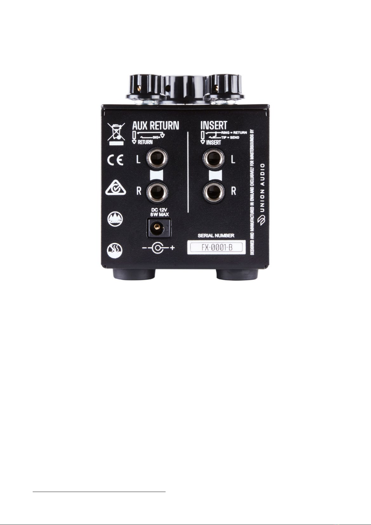
Both Aux In and Insert connections are on ¼” TRS jacks, with the Aux
In being fully balanced. Two pairs of high quality balanced Neutrik
leads are supplied with the unit, as well as a universal power supply,
enabling plug and play use anywhere in the world.
FX
Operation Manual Overview 4

3: Front panel controls
FX
Operation Manual Front panel controls
TIME – Select the FX time signature you wish to achieve by turning
the rotary dial.
FX SELECT – Rotate the FX select knob from 1-8. Each number represent s
a different effect. (See FX section on pg 6 for a description of
each effect).
5

Below the FX Select Knob shows 3 LED indicator lights with the FX number
and light code shown in the diagram above.
PARAMETER – You can select the amount of feedback/LF level, filter
resonance or threshold each effect has by turning the knob from MIN (no
feedback) to MAX, where the effect will have greater sustain in the mix.
FILTER – The filter knob enables high pass filtering on each effect,
from LOW to HIGH. WARNING! When set to LOW effects can be very powerful.
Experiment with FX frequency in the mix by tweaking the filter knob on
the fly.
RESONANCE – This knob adds resonance to the filter frequency knob. When
the knob is set to MIN and the filter frequency knob is turned clockwise
the filter will sound very natural. Turning the knob clockwise will add
resonance to the sound giving a more dramatic filter sweep in both HPF
& LPF modes.
DISTORTION – The distortion knob adds distortion to the signal when
turned clockwise from MIN to MAX, and is linked to the filter, so will
not work if one of the filter buttons isn’t selected. WARNING! The
DISTORTION knob is very powerful if set above MIN while the RESONANCE
is set around MAX. Take time to learn this feature.
FX
Operation Manual Front panel controls 6
Eect No
FX1
FX2
FX3
FX4
FX5
FX6
FX7
FX8
Eect Type
Stereo Pitched Delay
Delay Non Pitched
Delay Pitched Echo
Reverb
Bass Reverb
Gated Reverb
Gated/Delay Noise
Pitched Repeat
Time
Delay Time
Delay Time
Delay Time
Hall Size
Reverb Size
Reverb Size
Delay Time
Pitch
Paramater
Feedback
Feedback
Feedback
LF Level
LF Level
Threshold
Filter
Resonance
Filter
Resonance
Filter
HPF Frequency
HPF Frequency
HPF Frequency
HF Level
HF Level
HF Level
Filter Frequency
Filter Frequency
FX Description
Analog style delay with high-pass
filter
Mono delay with high-pass filter
Mono delay with reverb on feedback
General purpose reverb
Reverb with huge low-end response
Gated reverb with adjustable gate
Gated and delayed noise with band-
pass filter
Pitched repeat with HPF and res
FX NO
1
2
3
4
5
6
7
8
LIGHT CODE

SIDE CHAIN – When the DISTORTION knob is turned clockwise you will see
the SIDE CHAIN flash with a red LED (you will still be able to hear the
distortion circuit when the side chain doesn’t flash, and may need to
add more input trim to the signal to enable side chain). This indicates
that the circuit is being driven (see the overview section of the manual
for a description on how the circuit works).
FILTER FREQUENCY – This is the main control knob of the FX unit and
lets you control the amount of filtration sent to the EFFECTS section
and FILTER section.
Use the filter frequency knob to adjust the HPF, LPF & BPF (see below)
when each filter is activated, from 20hZ to 20khZ. Have fun tweaking the
frequency whilst adjusting the RESONANCE & DISTORTION knobs to create
intricate filtered effects.
HPF ON – Switch the HPF (high pass filter) on and off by pressing the
HPF button which illuminates the red LED.
LPF ON - Switch the LPF (low pass filter) on and off by pressing the HPF
button which illuminates the red LED.
BPF – Switching both HPF & LPF on at the same time activates the BPF
(band pass filter).
The filter frequency knob is linked to the EFFECTS section, and by
turning the knob from 20hZ to 20khZ you adjust the amount of selected
effect that’s sent to the main mix. There are 2 ways to use the FILTER
FREQUENCY knob. You can set up the AUX send knob on your MasterSounds DJ
mixer to the desired level, then use the FILTER FREQUENCY knob to add
the desired effect into the mix. At 20, no effected sound will be heard,
and by turning the knob clockwise the effect will be added to the mix.
You can also adjust the FILTER FREQUENCY knob prior to opening the AUX
knob on your MasterSounds DJ mixer. For instance, if you want to create
a
delay in the mix simply select the delay you wish on the FX SELECT knob,
then set the FILTER FREQUENCY knob to the desired frequency and turn the
AUX knob to hear the effect in the mix.
You can turn on the HPF, LPF or BPF when adding effects to the mix. This
creates a filter over the desired effect. Turn the FILTER FREQUENCY knob
clockwise to hear the effect, then press the desired filter. Experiment
with the RESONANCE & DISTORTION controls to create stunning filtered FX.
You can also experiment with the PRE button on your MasterSounds mixer.
The PRE button switches the Aux send feed from Post Fader to Pre Fader
(i.e. set to Pre Fader it will still send to the Aux Mix Buss with the
rotary fader down). Try experimenting with this feature to create some
great pre fader effects.
FX
Operation Manual Front panel controls 7

FX
Operation Manual Rear panel controls 8
Each MasterSounds FX is supplied with four quality TRS jack leads. These
are for connecting to your MasterSounds DJ mixer, and back into the FX.
To set up your FX unit simply follow the
instructions below:
Insert two of the supplied TRS jack leads to the AUX OUT on the rear of
your MasterSounds DJ mixer: L for the left channel and R for the right
channel. Then connect the leads to the corresponding L & R on the AUX
RETURN of the FX unit.
Once you have connected the AUX RETURN, insert two of the supplied TRS
jack leads to the AUX RETURN/INSERT on the rear of your MasterSounds DJ
mixer, once again L for the left channel and R for the right channel.
Then connect the leads to the corresponding L & R on the INSERT of the
FX unit.
Press the INSERT ON button on the rear of your MasterSounds DJ mixer,
Plug in the FX unit’s supplied power supply and attach to the mains.
The FX unit doesn’t have an on/off switch.
4: Rear panel controls

www.mastersounds.co.uk
FX Operation Manual
Copyright © 2018 MasterSounds Audio. All rights reserved 9
5: Warranty
MasterSounds warrants that the Mixer shall be free of defects in
workmanship and materials for a period of twelve months from the date
of purchase. In the event that the product fails to operate as intended,
MasterSounds will repair or replace the product subject to the following
conditions.
That the failure was not due to improper installation, operation,
cleaning or maintenance, accident, damage, misuse, abuse, or non-
approved modifications to the Mixer.
The warranty does not cover normal wear and tear or any other event,
act, default or omission outside MasterSounds control.
Faulty products must be returned to MasterSounds or an authorised
service agent along with the original invoice or proof of purchase,
and the mixer must be returned packed in the original shipping box.
Please contact MasterSounds before shipping a faulty unit.
The warranty applies only to the original purchaser and is not
transferrable.
At their sole discretion, MasterSounds may either repair the defective
product or replace with an equivalent service exchange item.
This warranty constitutes the purchaser’s sole remedy. MasterSounds
shall not be liable for any other repair or replacement cost or any
damage or loss directly or indirectly related to the malfunction of
this mixer.
1.
2.
3.
4.
5.
6.
MasterSounds FX complies with the European
Electromagnetic Compatibility directives
2014/30/EU and the European Low Voltage
directives 2014/35/EU.

6: Technical specication
Dimensions
Weight
Packed Dimensions
Packed weight
Power Requirement
External Power Supply
DC Internal Power Rails
Audio Performance
Noise
Distortion THD+N
Maximum Signal Level
Frequency Response
Filter Range
FX
Operation Manual Technical specification 10
MasterSounds reserves the right to change the specification without notice.
80W x 190D x 80H
0.8KG
290W X 220D 180H
1.8KG
Universal 90V – 265V AC 50/60Hz
12V 5W MAX
+/- 18V DC
<-95dBu 20Hz to 20kHz un-weighted
0.003% Insert IN to Insert OUT 0dBu
±21dBu
10Hz – 50kHz +0/-1dB
20Hz to 20kHz


FX Operation Manual
Copyright © 2018 MasterSounds Audio. All rights reserved
www.mastersounds.co.uk
Table of contents
Other MasterSounds Dj Equipment manuals
Popular Dj Equipment manuals by other brands

Lightronics
Lightronics FXLD336ZM3I owner's manual

KAM
KAM LED PARTYBAR instruction manual

Chauvet
Chauvet Mini Sphere CH-260 user guide

VDC Display Systems
VDC Display Systems Marquee 8520 Ultra quick start

Quarkpro
Quarkpro FS-3000D user manual

Velleman
Velleman HQ-POWER COPERNICUS IV LED MOONFLOWER 469... user manual