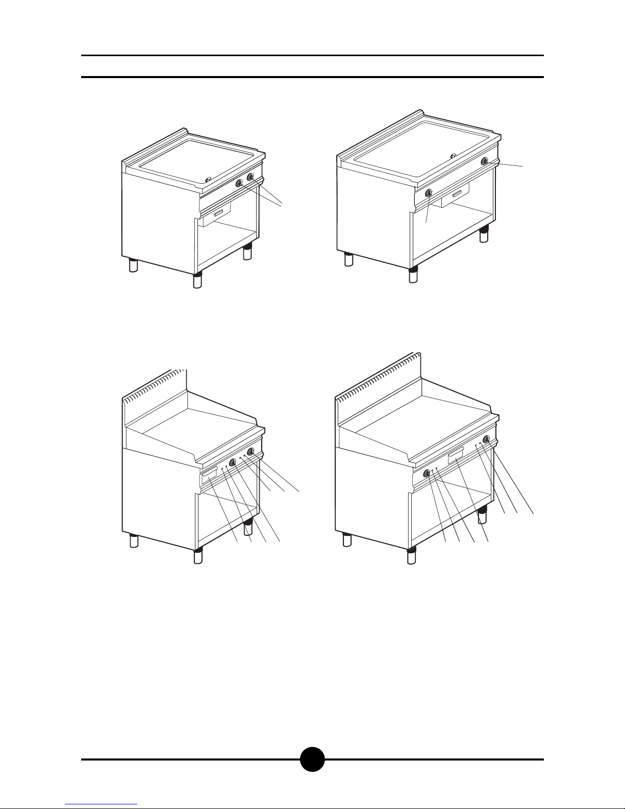
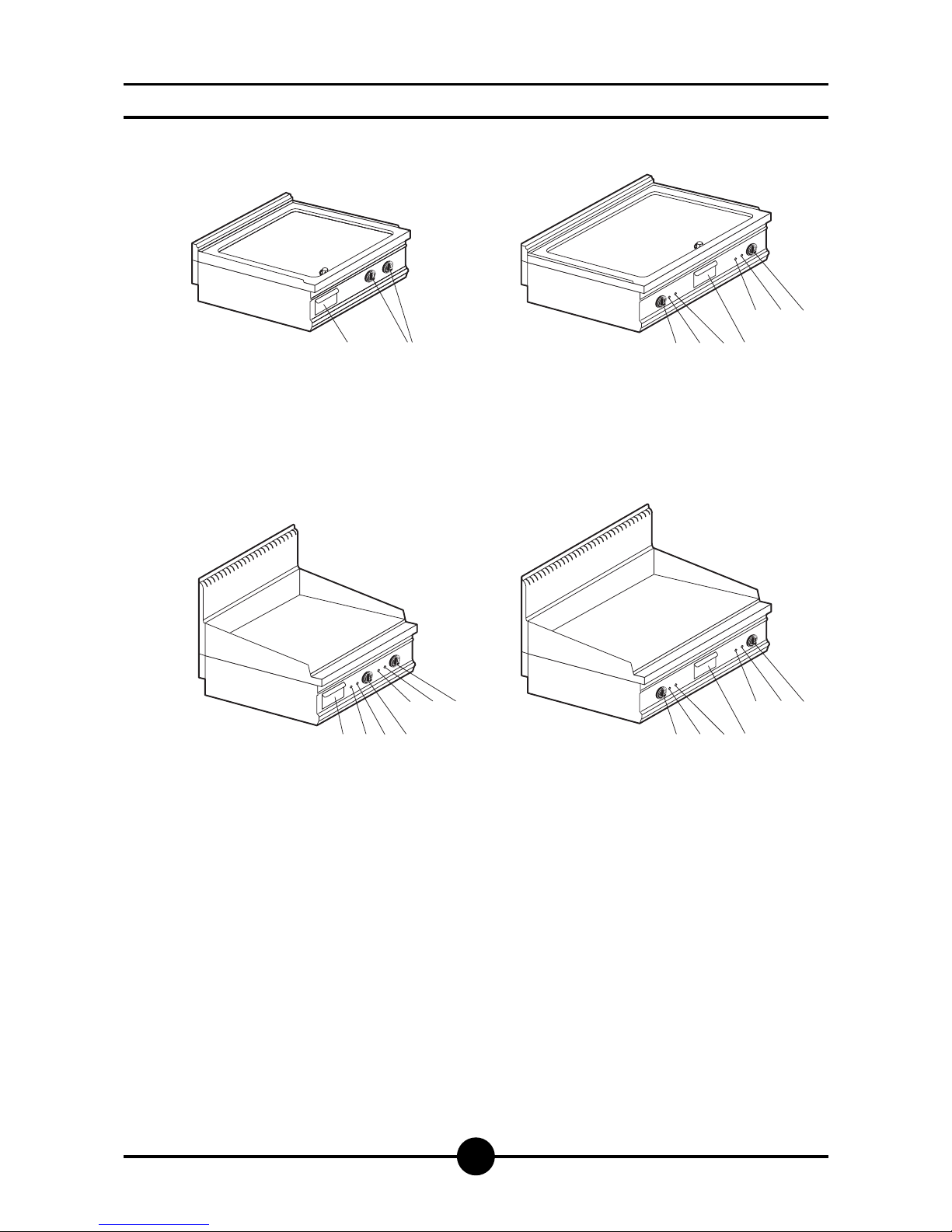
004-03 - Electric fry-top 10
Before beginning installation, remove all packaging from
the appliance. Some parts are protected with an adhesive
film which should be carefully removed.
Any remnants of glue should be thoroughly cleaned using
suitable substances such as benzine. Under no circum-
stances should abrasive substances be used.
Fit the legs to the appliance; the appliance must be level-
led using a spirit level. Slight irregularities can be levelled
by adjusting the feet themselves.
With table models, make sure that the base chosen is ca-
pable of supporting the weight of the appliance. The main
switch or plug should be located in the vicinity of the ap-
pliance and easy of access. We recommend installing the
machine under a range hood so that all the fumes are re-
moved as quickly as possible. If the appliance is to be in-
stalled near walls, dividing walls, kitchen equipment or de-
corative pannelling, these should be in non-inflammable
material or covered with non-inflammable material.
Make sure that all fire prevention standards and safety pre-
cautions are strictly adhered to.
Warning!
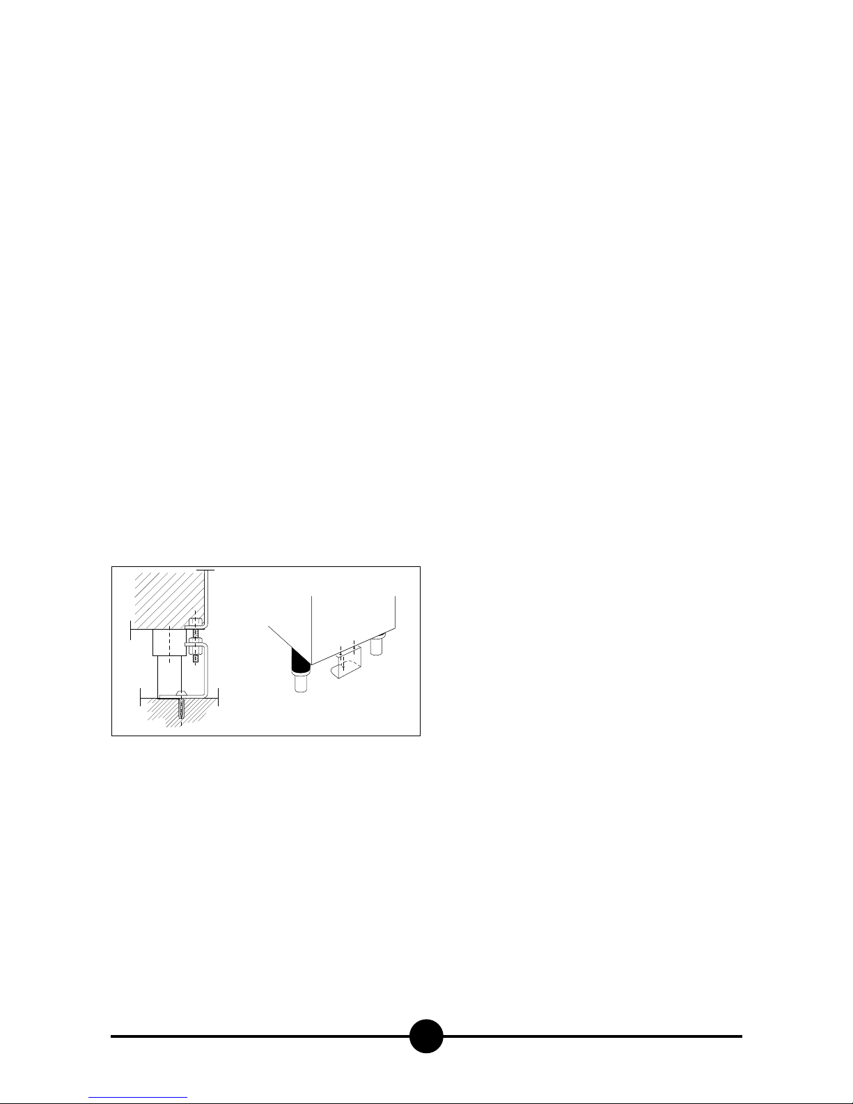
MODEL ACH30001/2/3
if this model is going to be mounted on its own, it must
be fixed to the floor. Fixing accessories are included.
The appliance should be fitted following the indica-
tions given in the drawing below.
Legal and technical requisites
When installing the appliance, the following safety stan-
dards must be adhered to:
- Local accident prevention standards
- Current CEI standards.
Installation
Installation, start-up and maintenance should only be car-
ried out by expert personnel. All work required to install
the appliance should be carried out in compliance with all
local standards and regulations. The manufacturers decli-
ne all responsibility where poor performance is due to in-
correct installation in disregard of the above conditions.
Warning!
In compliance with international regulations, when
connecting the appliance to the mains power supply, a
device with a minimum aperture of 3 mm between con-
tacts must be fitted upstream of the appliance, al-
lowing omnipolar disconnection of the appliance from
the mains.
Wiring
When choosing the lead wire, make sure it has the fol-
lowing characteristics: it should be at least of the H07 RN-
F type and its section should be large enough for the ap-
pliance (see "Technical specifications and dimensions",
page 9).
Wire entry on top models is on the back wall, and under-
neath all other models. In both cases the terminal board is
at the front, behind the control panel.
Pass the wire through the core hitch and wire clamp, plug
the leads into their terminals on the board and secure
them.
The earth lead must be a little longerthan the others so
that it is the last lead to disconnect if the wire clamp
breaks.
Unipotential
The appliance must be connected up to a unipotential sy-
stem. The connection screw is located on all top models at
the back on the right hand side, while in other models it is
located underneath the appliance on the right hand side.
It is labelled.
Warning!
The manufacturers cannot be held responsible for any
damage due to inadequate or incorrect installation.
Under such circumstances the guarantee will be consi-
dered null and void.
Start-up
Before using the appliance for the first time, thoroughly
clean the grilling plate (see “Cleaning and Taking Care of
the Appliance”) to remove the protective film of mineral oil
applied in the factory.
Check installation and wiring, then turn the appliance on
following the instructions below, and leave on, empty, for
about 15 mins.
INSTALLATION INSTRUCTIONS