14MM-JA08, 14MM-JA16 & 14MM-JA32
INSTRUCTION MANUAL
GENERAL SAFETY INSTRUCTIONS
Read these instructions carefully before connecting the device
To prevent re, short circuit or electric shock hazard:
• Do not expose the device to rain or moisture of any kind.
• Install the device in a dry location without inltration or
condensation of water.
• Do not place objects lled with liquids on the device.
• If any liquid should accidentally spill into the cabinet or onto
the device, disconnect the power plug.
To avoid any risk of overheating:
• Install the device in a well aired location and keep a minimum
distance of 15 cm around the device for sufcient ventilation
• Do not place any items on the device that might cover the
ventilation holes.
• Do not place any naked ame sources on or near the device
• Do not install the device in a dusty location.
• Follow the minimum and maximum temperature specications
To avoid any risk of electrical shocks:
• Connect devices only to power outlets with protective earth
connection.
• The mains plug shall remain readily operable
• Disconnect power plug to connect or disconnect any RF cables.
• To avoid electrical shock, do not open the housing of the device.
Maintenance:
• Only use a dry soft cloth to clean the outside of the device
• Do not use solvent
• For repairing and servicing refer to qualied personnel
Dispose of in a responsible manner and recycle where possible.
CONDITIONS OF WARRANTY
Matchmaster warrants the product as being free from defects
in material and workmanship for a period of 24 months starting
from the date of sale. See note below.
If during this period of warranty the product proves defective,
under normal use, due to defective materials or manufacturing,
Matchmaster, at its sole discretion, will repair or replace the
product. Return the product to your local dealer for reparation.
The warranty is applied only for defects in material and
manufacturing and does not cover damage resulting from:
• Misuse or use of the product out of its specications
• Installation or use in a manner inconsistent with the technical
or safety standards in force in the country where the product
is used
• Use of non-suitable accessories (power supply, adapters,
etc)
• Installation in a defect system
• External use beyond the control of Matchmaster such as
Accidental dropping, Lightning Strikes, Water damage,
Improper Installation or Ventilation, Storm or Tempest etc.
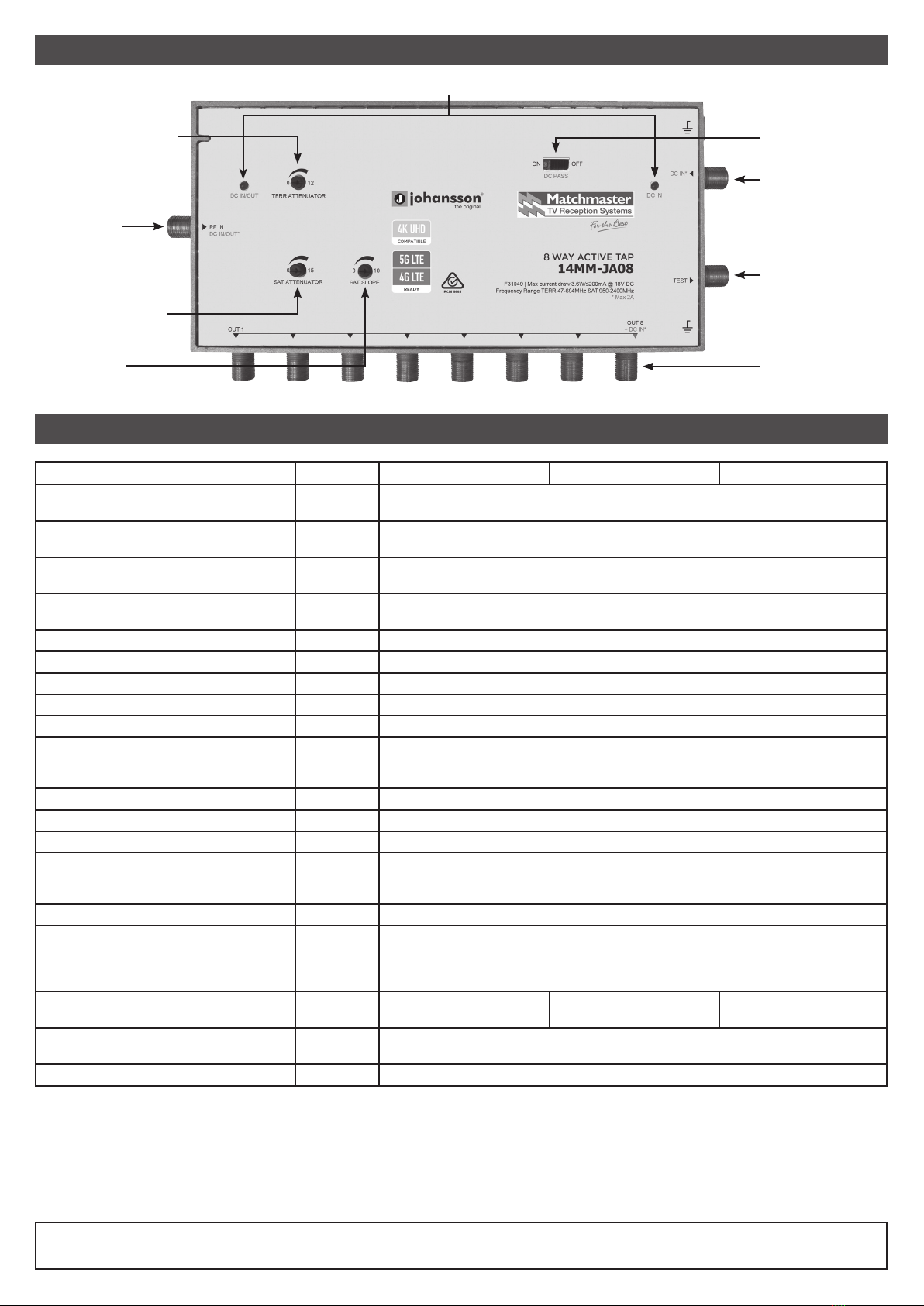
PRODUCT DESCRIPTION
IMPORTANT
INSTALLATION
POWERING OPTIONS
ADJUSTMENTS
CABLE CONNECTIONS
CABLE CONNECTIONS
• Active tap developed for single cable (Foxtel) SMS systems
• TERR + SAT input are ltered before amplication, slope
control and attenuation is applied then is split out to 8, 16 or
32 ways
• Output level will be greater than input level
• Can be DC powered via 3 ways: DC in, RF in and 1 RF out
port indicated on label
• Please read this instruction carefully for correct use of the
product and store it for future reference purposes.
• All the examples and pictures used here are for reference
only.
• The contents of this manual are subject to change without
notice.
The JA08, JA16 & JA32 are intended for indoor use.
Install the active taps so there is free circulation of air
(minimum of 15cm free space around the device) around the
tap and sufcient space for the cable connections.
1. Local Powering: Connect to the DC input F port.
2. Remote Powering: Integrated power via the input F port.
3. Line Powering: Can be line powered via an output port
(see diagram 1.0)
Attenuation: Set the Attenuation pots for both Satellite and
Terrestrial according to network design or requirements.
Equalisation (Slope): Set the equalisation pot for Satellite to
network design or requirements, Terrestrial slope is xed.
See diagrams 1.0.
Power up via the RF input: DC Switch needs to be in the OFF
position.
Power up via the RF output port: DC Switch needs to be in the
“OFF” position
Powering via the Auxiliary DC input and Line Powering to
additional Active Taps: DC Switch in “OFF” position, only
select the switch to the “ON” position to send power out via
the RF input to line power additional devices (Maximum 4
Active taps per power supply)
The warranty is not applied if:
• Production date or serial number on the product is illegible,
altered, deleted or removed.
• The product has been opened or repaired by a non-
authorized person.
Note: Date of production can be found in the product’s serial
number code. The format will either be “YEAR W WEEK” (e.g.,
2017W32 = year 2017 week 32) or “YYWW” (e.g., 1732 = year
2017 week 32).