Form 824889 Page Number - 9
mended pressure. Do not exceed 1.4 bar
(20 psi) pressure.
11. Connect a bleed reservoir to the bleed
screw of the first cylinder to be bled.
12. Open the bleed screw. Allow fluid to flow
out until only clear new fluid with no visible
air bubbles is streaming from the screw,
and then re-tighten the bleed screw to the
manufacturer’s recommended torque.
13. Perform the same procedure on all remain-
ing bleed screws. Operate the pressure
pump as required to maintain adequate
pressure.
NOTE: Do not allow the fluid transfer bottle
and master cylinder reservoir to run dry. Use
the pressure relief lever on the hand pump
to relieve the system pressure and add new
fluid if necessary.
14. Once bleeding is complete, relieve the pres-
sure in the system by activating the pressure
relief lever on the hand pump.
15. Close the fluid dispensing hose shutoff
valve, disconnect the fluid hose by pulling
back on the coupler sleeve, and carefully re-
move the adapter from the master cylinder,
being careful not spill any brake fluid.
16. Extract excess fluid or top-off the master
cylinder as required, and replace the cap.
17. Dispose of any hydraulic fluid remaining in
the fluid transfer bottle. Do not store hydrau-
lic fluid in the bottle. Clean the fluid transfer
bottle assembly with denatured alcohol and
store it properly.
18. Test the brake or clutch system for leaks
before driving the car.
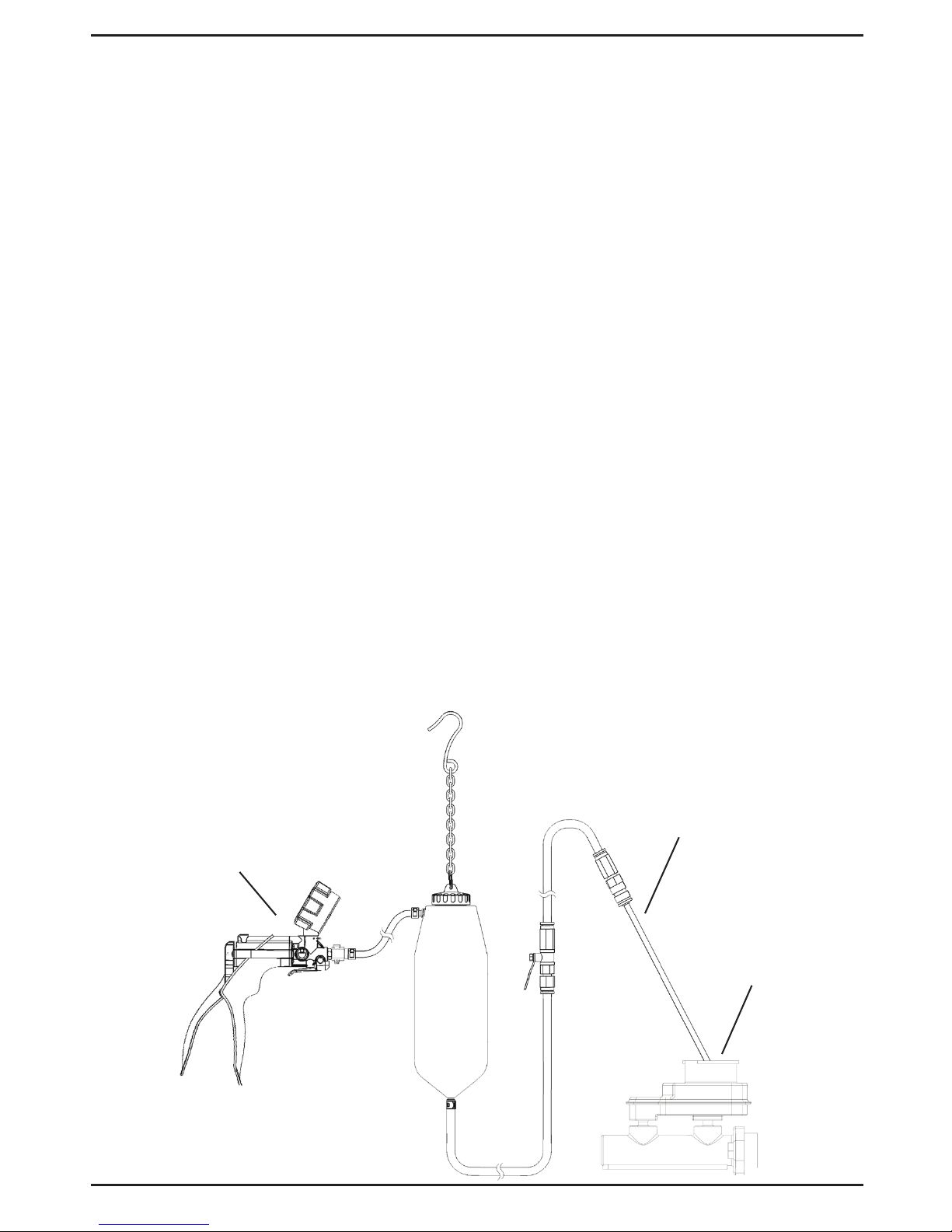
Vacuum Brake Bleeding
The Fluid Transfer Accessory Kit provides a
simple, clean, and quick method for vacuum
bleeding the fluid lines in an automotive brake
system. It operates by creating a vacuum in the
bottle, which draws fluid from the lines via the
wheel cylinder bleed screws.
1. Ensure the vehicle is properly positioned
for safe, convenient access to the master
cylinder, and the brake bleed screw located
on each wheel brake cylinder. Set the park-
ing brake, turn off the engine, and open and
secure the hood.
NOTE: Make certain the master cylinder
reservoir is filled and a supply of new, clean
brake fluid of the proper type is on hand to
top off the reservoir as the fluid level drops
during bleeding. Make sure all the bleeding
fittings are clean prior to beginning of the
bleeding procedure.
NOTE: Consult the vehicle manufacturer’s
guidelines for the proper wheel bleeding
sequence and vacuum bleeding procedure.
2. Disconnect the quick-change coupler from
the end of the fluid hose extending from the
bottom of the fluid transfer bottle by pulling
back on the blue sleeve of the coupler to
release it from the hose.
3. Insert the appropriate brake bleed adapter
into the end of the fluid hose in place of the
coupler.
NOTE: Brake bleed adapters are not in-
cluded with the fluid transfer accessory kit,
but come standard with most Mityvac hand
pump kits, or can be purchased separately.
In many cases, the end of the fluid hose can
be slipped directly onto the bleed screw
nipple, eliminating the need for a brake
bleed adapter.
4. Following the vehicle manufacturer’s recom-
mended bleed procedure, hang the fluid
transfer bottle assembly in a safe, secure
location within reach of the first wheel cylin-
der to be bled, and open the shut-off valve
located on the fluid hose assembly.
5. Connect a Mityvac hand vacuum pump to
the inlet hose extending from the side of the
fluid transfer bottle.
6. Slide a wrench securely onto the hex of the
wheel cylinder bleed screw, and then slip
the bleed screw adapter or fluid hose over
the bleed screw nipple.
7. Operate the hand pump 10 to 15 times to
build vacuum in the fluid transfer bottle,
and turn the wrench to open the fitting only
enough to allow fluid to flow; usually 1/4 to
1/2 turn.
NOTE: A tiny stream of bubbles may be
noticed in the hose after all of the air is bled
from the lines. This is caused by air seeping
around the threads of the loosened bleeder
fitting and being drawn back through the
fitting by the suction of the pump. Once the
air is removed from within the system, these
tiny bubbles will in no way jeopardize the
bleeding operation, since they are present
only at the fitting and do not enter the sys-
tem. Applying grease or Teflon tape around
the threads of the fitting will eliminate most
of the bubbles.