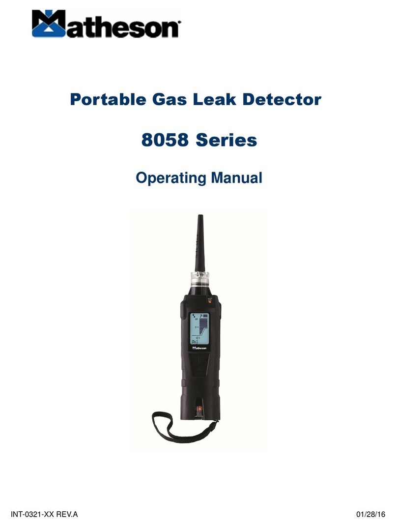
Matheson 8068 User manual

Model 8068
Gas Leak Detector
Instrument User Manual
INT-0368 rev A


3
SAFETY
QUALITY ASSURANCE
RESPONSIBILITY OF USE
DISPOSAL
CALIBRATION FACILITY
LEGAL NOTICE
INSTRUMENT DESCRIPTION
PACKING LIST
HOW 8068 WORKS
GETTING STARTED
INSTRUMENT MAIN SCREEN
USING THE 8068
HOW TO CONDUCT A CALIBRATION CHECK
INSTRUMENT MAIN SCREEN EXPLAINED
MAIN MENU
CALIBRATION MANAGEMENT
SYSTEM SETTINGS
PROBE OPTIONS
DETECTING LEAKS
INSTRUMENT SPECIFICATIONS
INSTRUMENT WARRANTY AND SERVICE
2
3
4
5
6
7
8
9
10
10
11
12
14
16
18
20
21
22
4
4
4
4
4
4
11
11
11
22
22
23
DECLARATION OF CONFORMITY
TABLE OF CONTENTS
STATEMENTS
WARRANTY
SERVICE
CONTACT DETAILS
SENSITIVITY
READING DISPLAY
MEASUREMENT UNITS

4
Statements
Safety
Please read this manual in full before using the 8068 instrument. MATHESON takes no respon-
sibility for damage, injury or death resulting from misuse, misunderstanding or negligence
while using this gas detector. Please contact MATHESON for clarification on any aspect of this
manual that is not understood or for additional information required.
This instrument should only be used by qualified or competent persons with suitable knowl-
edge of the hazards relating to the gases contained within equipment or in the local environ-
ment.
Quality Assurance
8068 instruments are manufactured in compliance with ISO9001, which ensures that the
equipment supplied to the customer has been designed and assembled reproducibly from
traceable components, calibrated to traceable standards.
Responsibility of Use
Many gases are hazardous and can cause explosion, poisoning and corrosion resulting in dam-
age to property and life. It is the responsibility of the person using this instrument to ensure it
is being used in accordance with this manual and that the instrument is functioning correctly
before use.
The 8068 can detect a large range of gases but some gases are more dicult to detect.
It is the responsibility of the user to ensure the 8068 instrument has the sensitivity to detect
the required gas before reaching potentially dangerous levels.
Inadequate performance of the gas detection equipment described in this manual may not
necessarily be self-evident and consequently equipment must be regularly inspected and
maintained. MATHESON recommends that personnel responsible for equipment use institute
a regime of regular checks to ensure it performs within calibration limits and that a record be
maintained which logs calibration check data. The equipment should be used in accordance
with this manual, and in compliance with local safety standards.
Disposal
Disposal of the 8068, its components, and any used batteries shall be in accordance with local
and national safety and environmental requirements. This includes the European WEEE (Waste
Electrical and Electronic Equipment) directive.
Calibration Facility
MATHESON oers a calibration service including the issue of certification confirming calibra-
tion to NIST standards.
An 8068 Calibration Kit oers a means of checking and calibrating the instruments against a
known reference, however MATHESON strongly recommend the instrument is returned to an
approved service center on an annual basis for general maintenance and calibration.
Legal Notice
While every attempt is made to ensure the accuracy of the information contained in this man-
ual, MATHESON accepts no liability for errors or omissions, or any consequences deriving from
the use of information contained herein. It is provided “as is” and without any representation,
term, condition or warranty of any kind, either expressed or implied. To the extent permitted
by law, MATHESON shall not be liable to any person or entity for any loss or damage which
may arise from the use of this manual. We reserve the right at any time and without any no-
tice to remove, amend or vary any of the content which appears herein.

5
Instrument Description
The 8068 is predominantly used for detecting gas leaks and can detect almost all gases to
varying degrees.
The 8068 uses thermal conductivity as its means of detecting gas, which oers a robust sen-
sor technology that requires practically no maintenance beyond annual servicing.
The 8068 has an easy-to-use graphical interface with an intuitive keypad allowing simple func-
tionality selection and adjustment.
The 8068 has a colored LCD display, LED indicator and audible sounder that indicates the de-
tected signal.
Common applications where the 8068 is already used include:
• Quality assurance - Testing seal integrity after product manufacture
• Laboratory applications - Detection of leaks from mass spectrometers and chromatograph
equipment
• Industrial - Leaks from gas cylinders, pipe work and process equipment
• Medical - Testing of membrane materials and sealing of glove boxes
• Pneumatic - Valve seal testing
The 8068 is calibrated against a 5 E-4 cc/s Helium leak to allow volumetric readings and also a
5000ppm Helium to allow measurement of concentrations.
Selectable Units:
cc/sec
ppm
mg/m3
g/yr
%Vol
Cubic Centimeters per Second oers a reading that indicates the volume of
gas escaping into atmosphere from a single point. ie. leakage from a hole in a
gas filled vessel or pipe.
Parts Per Million is a concentration reading, the 8068 will display the concen-
tration being detected however it is more dicult to gauge the quantity of
leakage.
Milligrams per meter cubed is also a unit that measures concentration. (See
ppm above)
Grams per Year is an alternative measure of leak rate.
This is a measure of the percentage of the target gas in the environment.
IMPORTANT NOTES:
• The 8068 is NOT intrinsically safe, so it should not be using in a potentially explosive environment.
Intrinsically safe instruments are available. Please contact MATHESON for more information.
• Ambient air pressure, heat and humidity can also aect readings.
• The 8068 range is NOT 'Gas Specific' i.e. It can NOT dierentiate between gases.

6
Packing List
Please remove all packing material and then check the content of the carry case against the
list below before use. Should the instrument or any accessory appear damaged or missing
then contact the instrument supplier for advice before use.
Model 8068:
• 8068 Instrument
• Box Spanner
• USB Cable
• USB Mains Adaptor
• Warranty Registration Card
• Quick Start Guide

7
How the 8068 Works
Thermal Conductivity
All gases conduct heat but by varying amounts, if an object is heated and then the source of
heat is removed, the object will eventually cool down to match ambient air temperature. This
action occurs because the ambient air surrounding the object carries the excess heat into the
surrounding atmosphere.
This principal is also the same for objects that are cooler than the surrounding ambient air.
Dissipation of heat into an air atmosphere is known and is a predictable rate, however, if the
ambient air is replaced with an alternative gas like Helium the rate at which an object cools
down changes.
If the object mentioned above had its environment replaced with pure Helium it would cool
down to the environment temperature about 6 times faster.
The 8068 contains a heated thermistor bead that transmits heat into the sensing chamber. On
the other side of the sensing chamber there is a block of material that remains at a constant
temperature helping to stabilize the signal. As air passes through the detector chamber a con-
stant amount of heat passes from the bead to the air. Gases that are dierent to air will aect
the rate at which heat transmits, these rates of change are measured and displayed as leak
rates.
The 8068 Thermal Conductivity Sensor
A piezo pump draws a small flow of gas through the probe and into the sensing chamber. The
thermistor bead heats up when electrical power is applied. As air passes through the chamber
a constant level of heat is transmitted to the air, this rate of heat transmission is used to 'Zero'
the instrument.
When gases with dierent thermal qualities pass through the chamber, the amount of heat be-
ing transmitted changes. These changes are measured and used to calculate a display reading
on 8068 for leak rates or gas concentrations.
Some gases have similar thermal properties to that of air; therefore, the 8068 can only
detect larger concentrations of these gases.
The 8068 can NOT dierentiate between gases, selecting a specific gas on the 8068 allows
the instrument to calculate concentrations of that gas only if that gas is being detected.

8
Getting Started
Charging Your 8068 Instrument
To charge your 8068 instrument, use a USB A to Type C Charger Cable and connect it to the
back of the 8068 device.
The 8068 instrument will indicate it's charging by showing the following symbol
at the top right of the home screen.
The Keypad
The following section explains the general functionality of each key:
'A'
Press ‘A’ to zero the 8068 readings. This
will remove any background readings and
return the display back to near zero.
'B'
Press ‘B’ to start datalogging. Press a sec-
ond time and the datalogging will finish.
UP
Use to scroll up on the LCD display and
change sensitivity.
SELECT/MENU
Use this to accept an option and enter the
Main Menu.
RIGHT
Use to scroll right on the LCD display.
LEFT
Use to scroll left on the LCD display.
DOWN
Use to scroll down on the LCD display and
change sensitivity.
ON/OFF
Press and hold this key for 5 seconds to
switch the instrument 'ON'. To switch the
instrument o, press and hold this key.
This procedure has been designed to avoid
accidental switch OFF.

9
Instrument Main Screen
Once the instrument has run through its 'Start up' routine it will display its normal 'Instrument
Main Screen' used when locating gas leaks. Before using the instrument, the various settings
should be set and adjusted to suit the application.

10
Using the 8068
WARNING: Before switching the 8068 on, ensure the ambient air is clean as the instrument
automatically Zero's the sensor at switch on. After the instrument has run through its start-up
routine, adjust the instrument settings to the desired levels. Check the instruments sensitivity
using a calibration kit.
Switch the 8068 on by pressing and holding the ON/OFF key, after the instrument has com-
pleted its Zero routine it will enter the main screen.
Gas leaks tend to occur at pneumatic joints or welded seams, hold the 8068 at a 45° angle to
the object being tested and drag the probe along the seam or joint at a rate of approximately
25mm per second.
When a leak is detected the bar graph will start to fill and the frequency of the audio out-
put will increase; this will decrease as the probe moves away from the leak. Return the probe
to the suspected leaking area and move slowly along the same area until the leak is located.
Once the leak has been located, the probe should be held at the leak until the numeric reading
stabilizes.
The live reading bar oers a graphical indication only and should not be used to measure a
leak; you may find that the graph completely fills however the numeric reading will continue to
increase.
Variation in temperature, humidity and background gas may result in a constant level being
detected on the instrument. To reset to Zero, hold the instrument away from the source of leak
or contamination and then press the ZERO key. The instruments display will return to a near
zero reading. It is especially important to move away from any toxic substances when Zeroing
the 8068 to avoid any false negatives which could lead to harm.
The following things will aect the instruments reading:
• Breath of the instrument user contains both CO2and moisture.
• Barometric air pressure and background temperature.
• Sources of cold and heat.

11
Instrument Main Screen Explained
The 8068 displays the 'Instrument Main Screen' whenever the instrument is being used to de-
tect gas, the illustration below outlines the various information and icons on the sheet.
Time Battery Percentage
Date
8068 Sensitivity
Reading Display
Gas Reading
Indicator
Measurement Units
Gas Reading
Current Gas
Selected
Sensitivity
The 8068 has three (3) sensitivity levels, high, medium, and low. You can adjust the sensitivity
by using the ‘UP’ and ‘DOWN’ arrow while on the instrument main screen. When the instru-
ment is set to low, it will increase in steps of 1000+. When set to medium, it will increase in
steps of 100. When set to high, it will increase in steps of 10 (when set to measurement unit:
ppm).
Reading Display
This is selected in the System Settings. It can be one of three possibilities. Standard readings
display will not register any readings below zero. Absolute, will measure both positive and
negative number but display all of them as a positive reading. Negative, will measure and dis-
play all negative and positive readings.
Measurement Units
You can find the measurement unit below the gas reading on the main screen. To change the
measurement unit, go to the main settings page. Scroll down to ‘Measurement Units’ and se-
lect your required measurement unit. Measurement units only appear when you have the cor-
responding calibration loaded.

12
Main Menu
To access the main menu, click the ‘MENU/SELECT’ button while on the main screen.
Current Calibration: The current calibration button provides you with information on when the
instrument was last calibrated, what gas was used, what the concentration was and what the
mV response was.
Load User Calibration: This option allows you to change between calibrations stored on the
instrument. Once you have selected your required calibration, ensure you press load to update
the current calibration.

13
Main Menu (Continued)
The Target Gas: This is where you can choose the desired gas you are looking to detect. This
will take you to a page with a drop down for the first letter of the target gas and the name of
the target gas.
The Measurement Unit: This is where you choose your desired measurement unit. The units
available depend on the selected calibration. If the Leak Calibration is selected the units avail-
able will be for leak rate. If the Concentration Calibration is selected the units available will be
for concentration.

14
Calibration Management
To access the Calibration Management on your 8068 instrument,
click the ‘MENU/SELECT’ button while on the main screen to
access the Main menu.
Once you are in the Main menu, use the ‘DOWN’ button and
click on ‘Calibration Management’ by pressing the
‘MENU/SELECT’ button.
The instrument will then start the ‘Pump calibration’.
Within Calibration Management, you can access the following:
Pump calibration: This option will run the pump calibration. The
temperature and pressure will be measured and used to set the
pump to the correct flow rate.
New calibration: This option will firstly provide you with two
options, concentration calibration (ppm) and leak calibration.
Please find ‘Concentration calibration (ppm)’ and ‘Leak calibra-
tion’ process below:
Concentration calibration (ppm): Select your chosen gas. To
select your chosen gas, select the first letter of the gas you are
looking to detect. Then press ‘DOWN’ to the next option and
search for the calibration gas. Once you have found the calibra-
tion, press the ‘MENU/SELECT’ button.
After you have confirmed the calibration gas, you will need to
type in the gas concentration. Press ‘save as’ and name the cali-
bration. Then press ‘DOWN’ and select ‘go’ to start calibration.

15
Calibration Management (Continued)
Once the pump calibration has finished, it will ask you to connect span gas. Connect the in-
strument to your span gas and press ok. You have the option to abort at this time if needed.
Once the instrument has stabilized, the calibration will finish. To confirm calibration, press ok,
again, you can abort at this stage if required. The calibration will then save to the instrument.
This calibration will automatically be added to the user load list.
Leak Calibration: The calibration process for leak calibration is very similar to the calibration
process for concentration calibration (ppm). The leak calibration will ask you to input the cal-
ibration gas and the name you would like to save the calibration as. The dierence is that the
leak calibration will ask you to input the leak rate (cc/s) of the calibration gas. Once the pump
calibration is complete you will supply the probe with the known leak rate (cc/s) of the calibra-
tion gas.
Expired Calibration: Once a user’s calibration has expired, it will appear in the Expired calibra-
tions drop down. The expired calibrations can be selected. Once selected the calibration can
be recreated by clicking ‘Recalibrate’.
Pending Calibration: Within calibration management you have ‘pending calibration’, this allows
you to send calibration details straight to the instrument.
Deleted Calibration: Delete calibration allows you to delete any custom calibrations that have
been saved onto the instrument.

16
Systems Settings
To access system settings, press the ‘MENU/SELECT’ button while on the instrument main
screen. The use the ‘DOWN’ arrow until you reach ‘System Settings’.
Within the system settings, you can view/adjust the following:
Peak Hold: When the peak hold is turned on the highest peak detected will be held on the
main screen.

17
Systems Settings (Continued)
Data Format (Decimals or Exponents): This is where you choose the
instruments display reading format, either decimals or exponents.
Readings Display: This is selected in the System Settings. It can be
one of three possibilities. Standard readings display will not register
any readings below zero. Absolute, will measure both positive and
negative number but display all of them as a positive reading.
Negative, will measure and display all negative and positive readings.
Sounder Volume: Allows you to adjust the alarm volume of the in-
strument (0-100).
Vibrations: This allows you to turn vibration on and o.
Screen Backlight: Allows you to adjust screen brightness level (10%-
100%).
Screen Timeout: Allows you to set how long the instrument display is
turned on. (O, 1-10 minutes)
System Information: Provides you with: model, serial number, firm-
ware, memory, battery remaining and bootloader.

18
Probe Options
In some applications, the probe cover might restrict access to the area that requires testing.
You can remove the probe cover by twisting it o from the instrument body (anti-clockwise).
Once the probe cover is removed, take care when using the instrument as the instrument
probe is delicate.
Removing the probe cover can help with pinpointing a leak more accurately by using the
probe sleeve.

19
Probe Options (Continued)
To refit the short or the long probe follow the steps above but in reverse order.
When using the box spanner to tighten the probe nut, ensure the nut is firmly tightened
however do not use additional tools as the tread may become damaged.
Should a probe become blocked, use dry, clean compressed air to blow out the blockage
from the instrument end of the probe. Ensure probe has been removed first.
The instrument has been factory calibrated using the standard short capillary which sets a
certain flow rate into the detector.
The long capillary by nature of its construction has a dierent flow to improve the time re-
sponse in detection. This will change the calibration of the instrument when the long probe is
used instead of the short capillary. Thus, the long probe is only to be used in finding leaks in
dicult places where the standard short probe cannot reach. The readings given by the long
probe are only qualitative and the reading given by the display is only to be taken as being
relative to another value given by another leak site while using the long probe.
Do not bend the flexible probe more than 90 degrees as this pushes the internal tube out-
side the protective sleeve.

20
Detecting Leaks
Hold the 8068 in one hand and draw the instrument probe along the area that requires testing
at approximately 25mm per second. When a leak is detected, retrace the route at a slower rate
until the leak is located. Once the leak is located, hold the instrument over the leak until the
measurement stabilizes. If you would like to log this reading you can click the B button to Start
Log. This will start a data logging session. To turn o the log when you are finished use the B
button again to Stop Log. The readings will then be saved to your 8068 instrument. You can
adjust the measurement sensitivity by using the ‘UP’ and ‘DOWN’ button. When detecting very
small leaks or detecting less sensitive gases, a rate of 10mm per second might be required.
The probe cover can be removed to allow better access to restricted areas, if the probe cover
is removed the following points should be noted:
• The probe sleeve needs to be added to the probe this ensures a 1mm gap is maintained
between the probe and the surface being tested.
• Avoid bending the inner probe as this will aect the instrument’s accuracy.
• Avoid placing the probe in liquid or dirt as the probe can become blocked.
• Care should also be taken to ensure the brass sensor housing component remains at a
constant temperature. Avoid touching the brass sensor block with fingers.
• The 8068 can detect changes in Humidity and Carbon dioxide, therefore avoid breathing on
the probe.
Table of contents
Other Matheson Security Sensor manuals