Emirel T 01N User manual

Viale Caduti per la Libertà, 4b - 40050 MONTE S. PIETRO - BOLOGNA (ITALY) –
Tel. 051/6761552 - Fax 051/6760492 - Internet: http://www.emirel.it - E-mail: info@emirelsrl.it – info1@emirelsrl.it 1
Release 20/05/19
RIVELATORE
D’ALBERO FERMO
CON ABILITAZIONE
ESTERNA - MULTISCALA
Nota: sostituisce il T 01 cambiando i
collegamenti sullo zoccolo.
DEFINIZIONE
Mediante un sensore amplificato (NPN
o PNP) o un sensore NAMUR (o un
contatto meccanico) il dispositivo
riceve un treno di impulsi di frequenza
proporzionale alla velocità dell’albero
da controllare; ad ogni impulso parte
un timer interno che dopo il tempo
“SP” manderà il relè in allarme; se
prima della fine di “SP” arriva un
impulso, il timer viene azzerato e
riparte (fig.1).
UTILIZZAZIONE
Permette di controllare il rallentamento
o l’arresto di un albero in rotazione.
T 01N
TAB. A
DETECTOR OF
STOPPED
SHAFT WITH
EXTERNAL ENABLE -
MULTIRANGE
Remark: it replaces T 01 changing the
wirings.
FUNCTION
The device receives from an amplified
sensor (NPN or PNP) or a NAMUR
sensor (or mechanical contact) a train
of pulses the frequency of which is
proportional to the speed of the shaft
to be controlled; at each pulse an
internal timer starts for the period TT.
The device is in alarm if after the
period SP there is no pulse. If before
the end of SP a new pulse comes, the
timer resets and it starts again (fig.1).
USE
It detects the deceleration or the stop
of a shaft.
ATTENZIONE: Verranno riparati in garanzia, franco ns sede, i dispositivi guasti per difetti sui materiali, entro 12 mesi dalla data di consegna. Emirel non è in alcun caso responsabile
per danni, diretti o indiretti, a persone o cose, che derivano da: mancato funzionamento, manomissioni, uso errato od improprio dei propri dispositivi di Protezione e Controllo.
Per le applicazioni
"
in SICUREZZA
" si consiglia l'uso di sistemi di SICUREZZA o l'uso di tecniche di "RIDONDANZA".
WARNING: Repairs in guarantee are made free our factory, within 12 months from the delivery date, for the devices not working due to defects of the components. In no case Emirel
can be held responsible for damages, direct or indirect, occurred to things or people in consequence of wrong connections, accidents, not correct use or not operation of the Protection and
Control devices of its own production. For the "safety applications", it is suggested to apply SAFETY systems or REDUNDANCY e
ngineering.".
NUMERO / NUMBER
DIP SWITCH
FUNZIONE
FUNCTION
CURSORE A SINISTRA
SLIDER TO THE LEFT
CURSORE A DESTRA
SLIDER TO THE RIGHT
DS2-1 RESET AUT/MAN
RIPRISTINO AUTOMATICO
QUANDO CESSA LA CAUSA
DELL’ALLARME.
IT IS ACTIVATED THE AUTOMATIC
RESET, AFTER THE ALARM CAUSE
IS GONE OUT.
RIPRISTINO MANUALE
MEDIANTE UN PULSANTE
N.O. TRA I PIN 10-2.
MANUAL RESET BY MEANS
OF A N.O. PUSH-BUTTON
BETWEEN THE PINS 10-2.
DS1-1÷6
IMPOSTAZIONE
GAMMA
/
SETTING RANGE
DS1 ON GAMMA
RANGE
-
1
2
1+2
3
1+3
4
1+4
5
6
20 ms
40 ms
100 ms
500 ms
2 sec
4 sec
10 sec
20 sec
30 sec
60 sec
DS2-4 RELAY ON/OFF
RELE’ NORMALMENTE ON IN
CONDIZIONE DI NON ALLARME
(SICUREZZA INTRINSECA).
RELAY NORMALLY ON IN NO
ALARM CONDITION (POSITIVE
SAFETY).
RELE’ NORMALMENTE OFF
IN CONDIZIONE DI NON
ALLARME.
RELAY NORMALLY OFF IN
NO ALARM CONDITION.
DS2-2
DS2-3 SENSORI NPN / PNP
ABILITA SENSORE PNP
CURSORE 3 A SINISTRA E
CURSORE 2 A DESTRA
ABILITA SENSORE NPN (NAMUR)
CURSORE 3 A DESTRA E
CURSORE 2 A SINISTRA
ENABLE PNP SENSOR
SLIDER 3 TO THE LEFT
SLIDER 2 TO THE RIGHT
ENABLE NPN (NAMUR)
SENSOR
SLIDER 3 TO THE
RIGHT AND
SLIDER 2 TO THE LEFT
NOTA 1: I DIP-SWITCH DS2 2-3 DEVONO SEMPRE TROVARSI UNO A DESTRA E
L’ALTRO A SINISTRA E VICEVERSA.
REMARK 1: THE DIP-SWITCHES DS2 2-3 MUST ALWAYS BE ONE TO THE RIGHT AND
THE OTHER TO THE LEFT AND VICE VERSA.

Viale Caduti per la Libertà, 4b - 40050 MONTE S. PIETRO - BOLOGNA (ITALY) –
2Tel. 051/6761552 - Fax 051/6760492 - Internet: http://www.emirel.it - E-mail: info@emirelsrl.it – info1@emirelsrl.it
CARATTERISTICHE E
REGOLAZIONI
PROGRAMMAZIONE DIP-SWITCH
Esegue la programmazione che deve
essere effettuata a priori, a seconda
del modo di funzionamento desiderato.
SP
Durata del periodo del timer, regolabile
a cacciavite sul frontale (diviso in 10
parti). Il fondo scala dipende dalla
gamma scelta mediante i DIP SWITCH
DS1 1-6 (Vedere in Tab. A).
TC
Temporizzatore (0,5÷15 sec)
regolabile a cacciavite sul frontale. E’
attivato dalla chiusura del contatto
“ENABLE” - ABILITAZIONE (pin 4-8).
Mantiene il T 01N disabilitato per la
durata del TC impostato per
permettere al sistema lento di andare
a regime.
ABILITAZIONE: (pin 4-8)
Mediante il contatto ABILITAZIONE è
possibile abilitare il dispositivo solo
quando è richiesto, in certe “fasi” della
macchina. Ad esempio, se il contatto è
quello del teleruttore che alimenta il
motore, si avrà la situazione espressa
nel diagramma (vedere fig. 2) e cioè:
•Alimentando il dispositivo il relè
interno si eccita, il contatto
ABILITAZIONE è aperto e non si ha
situazione di allarme, anche se
mancano gli impulsi.
•Parte il motore, si chiude il contatto
ABILITAZIONE, compaiono gli impulsi,
il relè resta ON.
•Mentre il contatto ABILITAZIONE è
chiuso, gli impulsi mancano o
rallentano, il LED “A” si accende ed il
relé commuta; per ripristinare il
dispositivo si dovrà premere Reset
oppure chiudere momentaneamente
un contatto tra i pin 2-10 (telereset) (se
il dip-switch DS2-1 è a destra).
•Il contatto ABILITAZIONE si apre e
quindi scompaiono gli impulsi; il relè
resta ON e non si ha allarme.
Se l’intervento del dispositivo fa
fermare il motore, è possibile
riconoscere se questo è fermo per
intervento dell’operatore oppure per
intervento del dispositivo stesso.
VISUALIZZAZIONI
ON LED VERDE alimentazio-
ne presente.
A LED ROSSO il dispositivo
è in allarme.
P LED GIALLO visualizza lo
stato “alto” dell’ingresso; per
frequenza superiore a 30 Hz
(1800 imp/min) il led appare
sempre acceso.
ENABLE LED GIALLO acceso
quando c’è abilitazione.
RIPRISTINO (pin 10-2)
Con il DS2-1 a sinistra è
AUTOMATICO.
Con il DS2-1 a destra é MANUALE
mediante la chiusura momentanea dei
pin 10
-
2.
TECHNICAL FEATURES AND
REGULATIONS
DIP-SWITCH SET UP
It is used to programme the conditions
of the device. It must be set for before
any other operation.
SP
Length of the period of the timer,
adjustable by screwdriver on the
front.(divided in 10 parts). The full
scale range is selected by the dip
switches DS1 1-6 (See in Tab. A).
TC
Timer (0,5÷15 sec) adjustable by
screw-driver on the front. It is activated
by closing the contact ENABLE (pin 4-
8). It keeps the T 01 out of operation
for the set period TC, in order to allow
a slow system to reach the regular
speed.
ENABLE: (pin 4-8)
The contact ENABLE activates the
device during the required phases of
machine operation: For instance if it is
a contact of the motor contactor, the
duty cycle is represented by the
diagram of fig. 2 as follows:
• The relay energizes when the device
is supplied; the ENABLE contact is
opened and no alarm condition takes
place even in absence of pulses.
• The motor starts up, the ENABLE
contact closes, the pulses appear, the
relay remains ON.
• During the closing of the ENABLE
contact the pulses fail or slow down,
the led “A” lights and the relay
changes over. The reset takes place
by pressing the push button RESET or
momentarily close a contact between
pins 2-10 (telereset) (if the dip-switch
DS2-1 is to the right.).
• The ENABLE contact opens and the
pulses fail; the relay remains ON and
no alarm condition takes place.
When the device makes the motor
stop, it is possible to know if the stop is
due to the operator or to an alarm
condition.
VISUALIZATIONS
ON GREEN LED supply on.
A RED LED the device is in
Alarm.
P YELLOW LED it points out
the “height” of the input:
when the frequency is higher
than 30 Hz (1800 pulses/
min)the led is always lighted.
ENABLE YELLOW LED device
enabled.
RESET (pin 10-2)
DS2-1 to the left, the reset is
AUTOMATIC.
DS2-1 to the right, the reset is
MANUAL, by closing for a short period
the pins 10-2.

Viale Caduti per la Libertà, 4b - 40050 MONTE S. PIETRO - BOLOGNA (ITALY) –
Tel. 051/6761552 - Fax 051/6760492 - Internet: http://www.emirel.it - E-mail: info@emirelsrl.it – info1@emirelsrl.it 3
FUNZIONAMENTO
Si veda ABILITAZIONE. Gli impulsi
sono in genere ricavati dal movimento
rettilineo o rotativo di opportune ruote
con denti, fori, sagome opportune ecc.
fig. 4 e 5. La durata minima del-
l’impulso deve essere >30µs.
Il dispositivo è sensibile solo al “fronte”
dell’impulso; ad albero fermo non ha
nessuna importanza che il sensore
veda un pieno o un vuoto.
Dopo la chiusura di abilitazione, il
primo impulso si deve presentare entro
il tempo TC impostato.
TARATURA
La scelta di SP è fatta in funzione della
frequenza degli impulsi. Es.: si vuole
riconoscere quando un albero che gira
normalmente a 200 giri/min rallenta a
10 giri/min.
•con una camma che fornisce un
impulso a giro si avrà 10 imp/min,
quindi l’intervallo fra un impulso e
l’altro è TP = 6 sec.; si dovrà scegliere
la gamma dei 20 sec. e porre la
manopola dopo la tacca 3 perché SP,
impostato con la manopola deve
essere maggiore del periodo degli
impulsi (ovviamente a 200 giri/min TP
è minore e quindi il SP risulterà ancora
maggiore). Nel caso di arresto
istantaneo dell’albero, il sistema
impiegherà al massimo il tempo SP,
prima di riconoscere la mancanza
degli impulsi.
•con una camma (o ruota fonica) che
fornisce 30 impulsi a giro si avrà 30x10
= 300 imp/min; quindi TP = 60/300 =
0,2 sec. Si dovrà scegliere la gamma
di 500 msec. e porre la manopola sulla
tacca 5 (0,25 sec). Nel caso di arresto
istantaneo dell’albero il sistema
impiegherà al massimo 0,25 sec. per
riconoscere la mancanza degli impulsi.
SICUREZZA INTRINSECA
(con DS2 n. 4 a sinistra).
La presenza degli impulsi coincide con
la condizione ON del relè; un guasto,
la mancanza dell’alimentazione ecc.,
portano il relè nella condizione OFF di
allarme.
INSTALLAZIONE
Eseguire i collegamenti di fig. 6.
(Collegamento a un quadro elettrico
con differenziale e sezionatore).
La lunghezza di ogni collegamento
deve essere < 30m.
INGRESSI
Sensori amplificati
NPN o PNP
4+
2-
3 ing.
Tensione fra 3
e 2: 15Vdc
1
0mA max
Sensori non
amplif
icati (NAMUR)
Contatti meccanici
puliti
3+
2 -
Massima
tensione fra 3
e
2: 8Vdc ±
10%
5mA max
Nota generale: Negli schemi di
collegamento non sono riportati i
fusibili sulle alimentazioni e sugli
ingressi voltmetrici.
I collegamenti elettrici devono essere
eseguiti a dispositivo e quadro
elettrico spenti.
General remark: The wiring diagrams
do not show the fuses installed on the
supply and on the voltmetric inputs.
The electric wirings must be realized
with device and electrical panel in off
condition.
COMPATIBILITA' ELETTRO
MAGNETICA
Electromagnetic compatibility
CEI-EN 61326-1
“BASSA TENSIONE” - LVD
LVD – “LOW VOLTAGE”
CEI-EN 61010-1
MODE OF OPERATION
Reference is made to paragraph
ENABLE. Generally the pulses are
given by the straight-line movement or
by the rotation of disks with holes
around the circumference or wheels
with teeth etc as per fig. 4 and 5. The
minimum duration of the pulse must be
>30µs.
The device is influenced only by the
edge of the pulse; when the shaft is
stopped it does not make any
difference if the device sees metal or
hole.
After the contact ENABLE is closed,
the first pulse must appear within the
TC set period.
SETTING
SP is selected on the base of the
frequency of the pulses.
Ex.: it is requested to detect when a
shaft turning at 200 RPM slows down
to 10 RPM
• by the application of a disk giving one
pulse per revolution, in correspon-
dence of 10 RPM there are 10
pulses/min so that the period between
two pulses TP, is 6 sec. It is necessary
to select the range of 20 sec. and fix
the knob after the third step, since SP
fixed by the knob must be higher than
the period of the pulses (obviously at
200 RPM TP is lower than 6 sec and
SP will be even higher). In case of
sudden shaft stop, the device needs
the time SP to detect the pulses
failure.
• By the application of a wheel (with
teeth on the circumference) giving 30
pulses per each revolution, 30x10 =
300 pulses/min; TP = 60/300 = 0,2sec.
The selected range is 500 msec; the
knob is set on step 5 (0,25 sec). In
case of sudden shaft stop, it is
necessary 0,25 sec for the system to
detect the pulses failure.
POSITIVE SAFETY
(dip-switch 2 n. 4 to the left).
In presence of the pulses the relay is
ON; when the relay is broken or the
supply fails, the relay goes OFF.
INSTALLATION ELECTRIC WIRING
As per fig. 6.
(Wiring to an electrical board with a
differential relay and a sectionalizing
switch).
The length of every wiring must be less
than 30m.
INPUTS
Amplified sensors
NPN or PNP
4+
2-
3 input
Voltage 15
Vdc between
3-2:
1
0mA max
Not amplified
sensors (NAMUR)
Mechanical
contacts free of
voltage.
3+
2 -
Max voltage
between 3-2:
8 Vdc ±10%
5mA max
NOTA 1
Se l’applicazione é in prossimità
di un inverter, si consigliano le
seguenti precauzioni:
- impiegare sensori amplificati
- usare cavi schermati
- il cablaggio dei “segnali” ed il
cablaggio della “potenza”
devono essere separati.
- usare cavo schermato nel
collegamento Inverter-motore
REMARK 1
If the device is close to the
application of an inverter, the
following precautions have to be
taken:
- apply amplified sensors
- apply shielded sensors
- the wiring of the “signals” must
be kept separate from the
wirings of the “power”
- apply shielded wire in the
connection Inverter-motor.

Viale Caduti per la Libertà, 4b - 40050 MONTE S. PIETRO - BOLOGNA (ITALY) –
4Tel. 051/6761552 - Fax 051/6760492 - Internet: http://www.emirel.it - E-mail: info@emirelsrl.it – info1@emirelsrl.it
USCITA
5A 230Vac carico resistivo
5-7 NA
5-6 NC
ALIMENTAZIONE: 2VA - 50÷60Hz
Tolleranza: ±10%
1-11: 230 Vac, 115 Vac, 24 Vac o
24 Vdc a richiesta.
TEMPERATURA DI
FUNZIONAMENTO: 0÷70°C
DIMENSIONI: 48x96x90 mm con
innesto per zoccolo undecal.
Accessori disponibili a richiesta:
E 171: ganci per montaggio da
incasso.
E 172: zoccolo femm.undecal per DIN.
M 13A: protezione plexiglas
piombabile IP54 (per montaggio a
pannello).
E 346: molle di sostegno
antisfilamento.
Dima di Foratura: 45x92 mm
PESO: kg 0,300 COLORE: nero
GAMME DI LAVORO
Programmabili mediante i DS1-1÷6.
Per la pulizia usare un panno imbevuto
con detergenti privi di: Alcool denatu-
rato, Benzene, Alcool isopropilico.
VARIANTI
T 01N-01
Variante 01 = TC: 0÷1 sec
T 01N-60
Variante 60 = TC: 0÷60 sec. max
OUTPUT
5A 230Vac resistive load
5-7 NO
5-6 NC
SUPPLY: 2VA - 50÷60Hz
Tolerance: ±10%
1-11: 230 Vac or 115 Vac or 24 Vac or
Vdc on request.
WORKING TEMPERATURE: 0÷70°C
SIZE: 48x96x90 mm -
undecal male base.
Accessories available on request:
E 171 : hooks for flush mounting.
E 172 : undecal female base for DIN.
M 13A: plexiglas protection IP 54-tight
closure (for flush mounting).
E 346 : hold wire protecting from
vibrations.
Template:45x92 mm
WEIGHT: kg 0,300 COLOUR: black
RANGES
Selected by the DS1-1÷6.
For cleaning use a cloth soaked with
detergents without: Denatured alcohol,
Benzene, Isopropyl Alcohol.
MODIFICATIONS
T 01N-01
Modification 01 = TC: 0÷1 sec
T 01N-60
Modification 60 = TC: 0÷60 sec. max
Other Emirel Security Sensor manuals
Popular Security Sensor manuals by other brands
Vaxcel
Vaxcel Lambda T0625 Assembly and installation instructions
Intermatic
Intermatic IOS-DOV-DT Installation and configuration instructions
Bosch
Bosch ISC-BPR2-W12 installation guide

APRVTIO
APRVTIO ALD-200 quick start guide

Knauer
Knauer Azura RID 2.1L instructions
Panasonic
Panasonic CX-44 Series instruction manual
Cattron
Cattron Safe-E-Stop user guide
Det-Tronics
Det-Tronics X3302 instructions
Visonic
Visonic DISCOVERY K9-80 MCW - INSTALLER GUIDE installation instructions
Texecom
Texecom Premier Elite MR Long Range installation manual
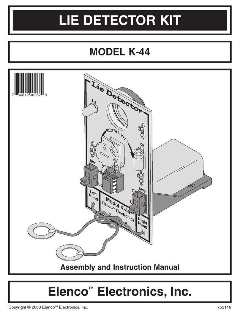
Elenco Electronics
Elenco Electronics K-44 Assembly and instruction manual

GTV
GTV Wenud Duo LD-WENDM13W-40 manual
